INSTALLATION MANUAL ROLLERSHADE HARDWARE SYSTEM
←
→
Page content transcription
If your browser does not render page correctly, please read the page content below

QUANTUM
     ROLLERSHADE HARDWARE SYSTEM

  I N S TA L L AT I O N MA N UA L

February 2014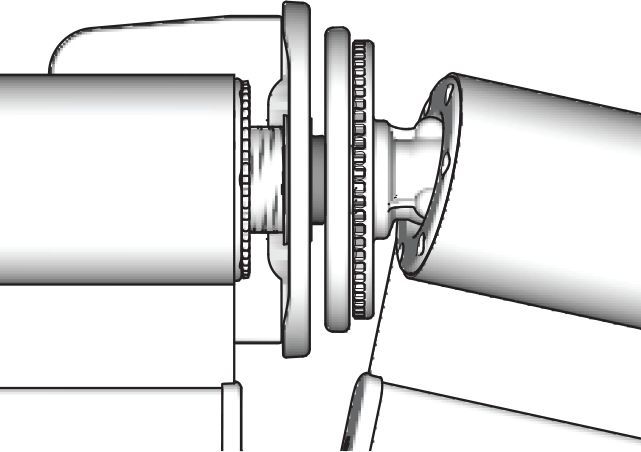
Q UA N T U M M E A S U R I N G D E D U C T I O N S

                          CORNERS                                           Corners in Reveal- Front Edge   Deductions
          Note: For windows in reveal brackets must be top
          fixed for deductions to work.
                                                                            Through Blind                   +50mm(from corner)
                           BACK EDGE
                                                                            Butt Blind                      - 0mm
                          FRONT EDGE

                           ON FACE                                          Corners in Reveal- Back Edge    Deductions
                                                                            Through Blind                   - 0mm
                                                                            Butt Blind                      - 60mm (37mm Tube)
                                                                                                            - 80mm (50mm Tube)

                                                                            Corners on Face                 Deductions (Butt Blinds)
                                                                            38mm Projection bracket         - 75mm
 Deductions are only approximate due to thickness of fabric and drop, for
 best results install the thru blind then measure for the butt blind.       55mm Projection Bracket         - 90mm

                              BAYS
                                                                            Bays in Reveal                  Deductions
                                                                            Front Edge of Reveal            - 0mm - 0mm - 0mm
                            TOP FIX BACK EDGE
                                                                            Back Edge of Reveal             - 22mm - 44mm - 22mm
                           TOP FIX FRONT EDGE

                                ON FACE

                                                                            Bays on Face                    Deductions
                                                                            38mm Projection Bracket         - 28mm - 56mm - 28mm
                                                                            55mm Projection Bracket         - 33mm - 66mm - 33mm

ANGLED LINKED BLINDS - BAY WINDOW
                             FACE FIT
                                                                            Angled Link Bay on Face         Deductions
                           MEASURE WALL
                     Brackets to be fixed to wall                           38mm Projection Bracket         - 38mm - 76mm -38mm
                                                                            55mm Projection Bracket         - 43mm - 86mm -43mm
                 CEILING FIT FRONT EDGE
                       OF REVEAL
                                                                            Angled Link Bay in Reveal       Deductions
                                                                            Front Edge of Reveal            - 10mm - 20mm - 10mm

                                                                            *Gap between Brackets 30mm approximate

ANGLED LINKED BLINDS - 90° CORNERS                                          Angled Link Corners on Face
                          FACE FIT
                                                                            Measure Blinds into the corner and deduct 76mm from each
                                                                            blind.

                                                                            Angled Link Corners in Reveal
                                                                            Measure from the front edge of reveal and deduct 10mm
                                                                            from each blind.
          TOP FIT FRONT EDGE of REVEAL
                                                                            In all corner linked situations we strongly recommend
                                                                            that the brackets are fixed in exact location first and then
                                                                            measured outside edge to outside edge of the bracket to
                                                                            ensure the gap is minimised.
                                                                            *Gap between Brackets 30mm approximate

                                                                             PAGE 2
Q UA N T U M                        I N S TA L L AT I O N
INSTALLATION - STANDARD ROLLER SYSTEM

1. Fix bracket with the screws       2. Place the chain drive in the    3. Slide it down until it
   provided                             bracket (1)                         clicks (2).

4. Place the tube adapter on the     5. Snap it to the bracket.        6. Slide the end caps onto the
   chain drive. Press the idle end                                        brackets.
   and lift the blind.

REMOVAL - STANDARD ROLLER SYSTEM

1. Slide a screw driver between      2. Move the blind downwards       3. Push the pin of the chain
   idle end and bracket and             out of the bracket.               drive and take the chain drive
   push the idle end in the chain                                         out of the bracket.
   drive direction. Slide the end
   cap towards you.

4. Place a screw driver under the
pin of the chain drive and pull it
outwards. Remove chain drive
from the bracket.

                                                  PAGE 3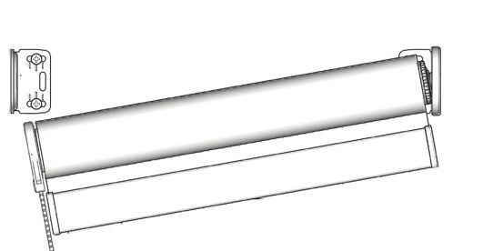
Q UA N T U M                          I N S TA L L AT I O N
INSTALLATION - STANDARD ROLLER SYSTEM WITH LEVELLER BRACKET

1. Make sure that the opening          2. To adjust skewing, put the
   for the Allen key is pointing          provided Allen key into the
   downwards before installing the        screw of the leveller and turn
   brackets. Change the orientation       it left or right to move the
   by loosening the 2 screws and          blind up or down.
   turning the leveller 90°. Fix the
   screws.

                                                     PAGE 4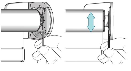
Q UA N T U M                         I N S TA L L AT I O N
INSTALLATION - LINKED BLINDS

1. Place the tube adaptor on the       2. Fix the outer bracket with the      3. Slide the aligner or the
    chain drive head. Press the           screws provided.                        connector through the
    idle end and lift the blind.                                                  bracket into the idle end.

4. Place the tube adaptor on the       5. Press the spring loaded idle         6. To align the bottom rails, push
   aligner or connector head.             with locking ring end and lift           the blind against the idle end
                                          the blind and snap it to the             (1), turn the blind, level the
                                          bracket.                                 bottom rail with the other one
                                                                                   (2). Release to fix the position
                                                                                   (3).
                                                                                  NOTE: This is not possible
                                                                                  when using the standard
                                                                                  connector set.

7. Fix the blind by turning the        8. Slide the end caps onto the
    locking ring against the idle          brackets.
    end.

NOTE:    The aligner component has an extra metal bearing ring which is only required if the centre space
         between two blinds is being extended. For normal installation this can be removed using an allen key.

                                                   PAGE 5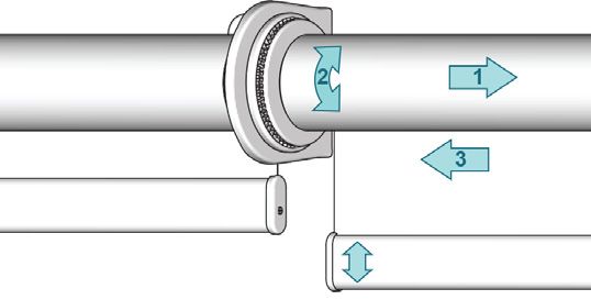
Q UA N T U M                         I N S TA L L AT I O N
    REMOVAL - LINKED BLINDS

    1. Slide the end cap towards          2. Unfasten the locking ring.      3. Move the blind downwards
        you.                                 Slide a screw driver between       out of the bracket. Pull the
                                             locking ring and bracket           aligner or connector out of
                                             and push the idle end in the       the idle end.
                                             aligner direction.

                Q UA N T U M                         I N S TA L L AT I O N
    INSTALLATION - SPRING BOOSTER

                            2                click
                    1

         2
1

                                                           3

    1. Place the idle end into the        2. Lift the blind up until chain    3. Fix the blind by turning the
       bracket. Push blind in the idle       drive clicks in place (3).          locking ring against the idle
       end direction (1) and lift blind                                          end.
       up (2).

                Q UA N T U M                         I N S TA L L AT I O N
    REMOVAL - SPRING BOOSTER

                                                                                                    2
                                                                                   3        1
                                                                                            2

                                                           1

    1. Unfasten the locking ring.         2. Slide up the chain drive.       3. Push blind in the idle end
                                                                                direction (2) and lower blind
                                                                                to remove from bracket (3).

                                                       PAGE 6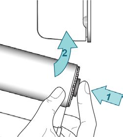
Q UA N T U M I N S TA L L AT I O N
INSTALLATION - HEADBOX SYSTEM
1. Fix headbox back plate to wall 2. Slide end caps into the 3. Clip headbox front plate inside
by drilling through extrusion headbox back plate. keyway at the top of the
and slide brackets into keyway. back plate.
Tighten grubscrew. NOTE: End cap removed for
demonstration only.
4. Clip headbox front plate into
place to secure the endcaps.
INSTALLATION - SIDE CHANNELS
1. Level the side guiding channel 2. Fix the top clip with a distance 3. Fix the lower clip - and clips
flush with the headbox end max 7.5mm from the bottom at 1000 mm intervals - before
cap. Mark this position. of the headbox end cap. installing the channel.
Tab
4. Place the bottom rail into the 5. Snap channel into clips.
side guiding channel. Snap
and remove tab on chain
drive end.
PAGE 7
Q U A N T U M                         M A N U A L

                 INSTALLATION MANUAL INFORMATION

This Installation Manual is only a guide to the measurement and installation procedures
for the Quantum Hardware System. New Zealand Window Shades Limited does not
warrant the accuracy contained in this manual.

The information contained in this Installation Manual is based on the measurement and
installation data known to us at the time of issue and is therefore subject to changes
or amendments at anytime without notice, and the right to change or amend is hereby
expressly reserved by New Zealand Window Shades Limited.

IMPORTANT
This Installation Manual at all times remains the property of New Zealand Window
Shades Limited. Its contents are strictly confidential and may not be reprinted, copied,
reproduced or multiplied in any form. This Installation Manual must be maintained in
its original form and must be returned to New Zealand Window Shades Limited upon
first request. New Zealand Window Shades Limited is not responsible to you or anyone
else for any loss suffered in connection with the use of this Installation Manual or any
of the content.

© Copyright 2014 New Zealand Window Shades Limited
® Registered Trade Marks of Hunter Douglas Limited.

                NEW ZEALAND WINDOW SHADES LIMITED

                           PO BOX 12 785 PENROSE,

                                 AUCKLAND 1642

                                  NEW ZEALAND

                  Customer Service Phone: 0800 223 224

                                        PAGE 8
You can also read