LASERMET LASER BLOCKING ROLLER BLINDS INSTRUCTION MANUAL - CERTIFIED LASER BLOCKING ROLLER BLINDS TO BS EN IEC 60825-4
←
→
Page content transcription
If your browser does not render page correctly, please read the page content below
Roller Blind Instruction Manual

                 LASERMET LASER BLOCKING
                      ROLLER BLINDS

                      INSTRUCTION MANUAL

                CERTIFIED LASER BLOCKING ROLLER BLINDS
                          TO BS EN IEC 60825-4

CEB00XXX-53-000                               Issue 8.2   26 April 2021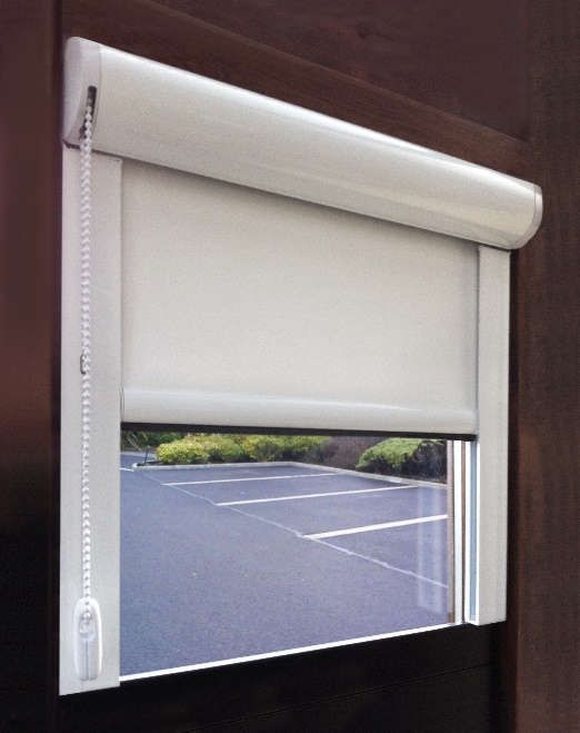
Roller Blind Instruction Manual

                                              LASERMET Roller Blind
                                                Instruction Manual

                                                               Contents

1    Declaration of Conformity .................................................................................................. 3

2    Safety Warnings .................................................................................................................. 4

3    Concept ............................................................................................................................... 5

4    Roller Blind Options and Specifications.............................................................................. 7

    4.1      Medium Chain-operated Laser Blocking Roller Blind ................................................. 7

    4.2      Medium Crank-operated Laser Blocking Roller Blind ................................................. 9

    4.3      Medium Motorised Laser Blocking Roller Blind ........................................................ 11

    4.4      Large Laser Blocking Roller Blind, Chain, Crank or Motor-operated ........................ 14

5    Installation ........................................................................................................................ 16

    5.1      Assembly ................................................................................................................... 20

6    Wiring ............................................................................................................................... 22

7    Maintenance ..................................................................................................................... 23

    7.1      Cleaning ..................................................................................................................... 23

    7.2      Laser Blocking Material Test Report ......................................................................... 23

8    Programming the Controller for Motorised Blinds .......................................................... 25

9    Specifications .................................................................................................................... 27

10        Warranty ....................................................................................................................... 27

11        Contact Details .............................................................................................................. 28

CEB00XXX-53-000                                              Page 2 of 28                          Issue 8.2             26 April 2021
Roller Blind Instruction Manual

1      Declaration of Conformity

                                        LASERMET LIMITED

                   LASER BLOCKING CURTAINS, ROLLER BLINDS & WINDOW BLOCKS

                        Made from Lasermet Material:       BLOCK-MAT-HP2
                                                           BLOCK-MAT-HP3WW
                                                           BLOCK-MAT-HP4BB

                                  DECLARATION OF CONFORMITY

     This is to certify that the Laser Blocking Curtains, Roller Blinds, & Window have been
     tested in accordance with the following directives and standards and found to comply.

     Lasermet certifies that this product complies with the basic requirements for health
     and safety as provided by the following directives and standards:

     Directives:        Machinery Directive 2006/42/EC

     Standards:         EN 60825-4:2006 +A1:2008 +A2:2011
                        Safety of Laser Products, Part 4 – Laser Guards

           Irradiated Area                  PEL (T3) 10s                     PEL (T2) 100s
                4 mm2                       3.9 MW/m2                         2.2 MW/m2
              2000 mm2                      0.62 MW/m2                       0.35 MW/m2

     Supplier:          Lasermet Limited
                        Lasermet House
                        137 Hankinson Road
                        Bournemouth
                        BH9 1HR
                        Dorset
                        United Kingdom

     Country of Origin: England

     Signed:

     Paul Tozer
     Managing Director

     Date: 11 February 2021

CEB00XXX-53-000                             Page 3 of 28                  Issue 8.2     26 April 2021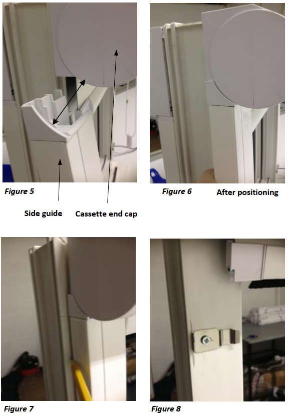
Roller Blind Instruction Manual

2       Safety Warnings

This device is intended to be used as part of a safety system which may be used to protect personnel
and equipment from possible injury, damage, or loss.

As such it must be installed and wired according to these instructions and tested by suitably qualified
persons. No attempt may be made to tamper with the parts, open them, or use them outside of the
parameters contained herein.

The units are only designed to be fixed to surfaces using their inbuilt fixing holes. They must not
come into contact with each other or any other moving part when in use. The parts should never be
subject to impact or mechanical strain.

Safety switches should never be defeated or bypassed. It is imperative that all steps are taken to
ensure that any spare actuators are made unavailable, such that they cannot be used to defeat the
switch or reduce the protection offered by the system in any way.

If the equipment is used in a manner not specified by Lasermet, the protection provided by the
equipment may be impaired.

Lasermet reserves the right to change the design, modify the operation of functions or add new
features at any time without prior notice.

CEB00XXX-53-000                              Page 4 of 28               Issue 8.2       26 April 2021
Roller Blind Instruction Manual
3 Concept
All Lasermet laser-blocking roller blinds are made from Lasermet’s specially developed laser blocking
material and are CE marked and certified to EN 60825-4 (Safety of Laser Products Part 4: Laser
Guards). (Hospitals in the UK should adhere to the requirements of the NHS Estates HBN 26 –
“Facilities for surgical procedures”).
Laser Blocking Roller Blinds
Made-to-measure to fit virtually any size of window, Lasermet laser blocking roller blinds are
available as encapsulated blinds and can be supplied for either surface or recessed mounting. The
maximum size is 4m width x 4m drop.
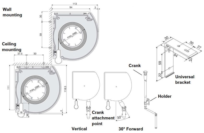
Encapsulated Roller Blinds
Lasermet’s encapsulated roller blinds are built into a white finish
aluminium frame, which encapsulates the top, both edges and
bottom of the blind. This eliminates any possibility of laser beams
passing round the sides of the blind, blocks out all direct light and
provides a neat finish. They are operated by either, a chain, crank
handle or electric motor.
Several options are available for the encapsulated laser blocking roller
blinds as follows:
Chain operated – Simple to operate and use.
Crank handle operated – Ideal for installations where the blind may be difficult to reach or
where chain operation is not appropriate.
Motorised (mains 230VAC) – Used where large heavy blinds are in operation.
Wireless – The end limits are set electronically using the switch.
Hard-wired – The end limits are mechanically set using grub screws.
24VDC Power Supply Warning - Lasermet’s power supply must be used. Using a different
24VDC supply can permanently damage the motor and will
invalidate the warranty.
24VDC wireless This is the most popular option where either single or multiple blind
sets can be used. For example, a room could have 4 blinds and they
could all be operated by a single switch if required. The end limits
are set electronically using the switch.
24VDC dry contact The low voltage provides an added level of safety, while eliminating
the wireless function for sensitive environments. The end limits are
set electronically using the switch.
CEB00XXX-53-000 Page 5 of 28 Issue 8.2 26 April 2021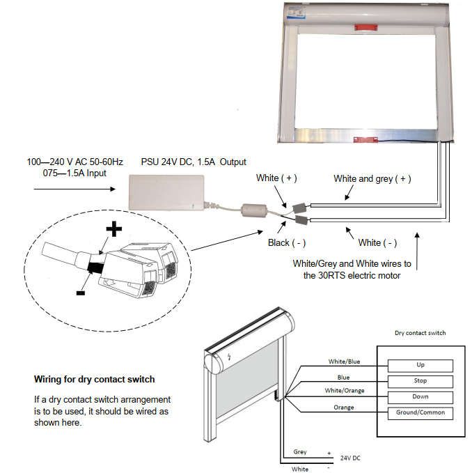
Roller Blind Instruction Manual

Interlocked Blind               A maglock switch is positioned at the bottom of the blind so that
                                when the operator switches the blind to be lowered the interlock
                                switch is energised. Either a single channel interlock can be used, or
                                a dual channel interlock switch can be used with the ICS Series of
                                Interlock controllers.

Integrated Interlocked Blind    The motorised blind can be connected to Lasermet’s interlock
                                controller which can then enable the motorised blind to close and
                                will only permit the laser to be powered once the interlock switch
                                has been closed confirming that the blind is down.

Lasermet provides a full range of laser interlock equipment including control systems, interlock
switches, illuminated warning signs, laser shutters, door locks, external power supplies etc. which
can be connected to provide a complete laser interlock system. Full support, design and installation
is available from Lasermet, please contact us for any queries. Contact details are given at the end of
this manual.

CEB00XXX-53-000                             Page 6 of 28               Issue 8.2       26 April 2021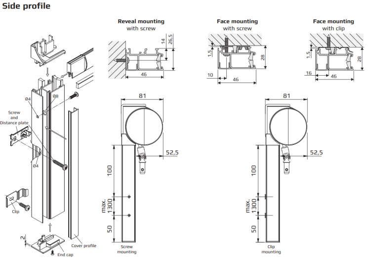
Roller Blind Instruction Manual

4       Roller Blind Options and Specifications

4.1 Medium Chain-operated Laser Blocking Roller Blind

Dimensions                   Width min.      0.3 m, max.     2.0 m
                             Height max.     1.5 m

Max. Braking Capacity        5.0 kg

Manually Operated Blind      Side-pull gear with protection against unwinding by means of a
                             brake mechanism.
                             The brake mechanism permits the exact, stepless positioning of the
                             blind in any desired position.

Cassette Profile             Round 78.0 x 77.5 mm extruded aluminium (Al Mg Si 0,5 F22) fitted
                             on the round end cap of the brackets
Tube Shaft                   Ø27.0 / Ø36.0 mm steel (0.35 mm K40)
Precision Shaft              Ø29.0 / Ø38.0 mm extruded aluminium (Al Mg Si 0,5 F22)
Two-profile Bottom Rail      13.0 x 29.0 mm extruded aluminium (Al Mg Si 0,5 F22)

Plastic Parts                High-quality, UV-resistant, temperature-resistant, abrasion-proof

Profile Guiding              Roller blind material extends 20 mm on both sides into the profile
                             guiding.
Angle of inclination         max. 15°
Profile                      Colour matches the cassette colour.
Profile Dimensions           Cross section 46.0 x 26.0 mm
                             Length          max. 4.0 m

Operation                    Manual operation with nickel-plated steel ball chain Ø4.5 x 6.0 mm
Operation Side               Optional left or right
Operation Height             Roller blind height x 0.75 (or individual)
Bead Stop                    By matching chain connector
Colour                       Powder coated white (RAL 9016)

CEB00XXX-53-000                          Page 7 of 28                Issue 8.2     26 April 2021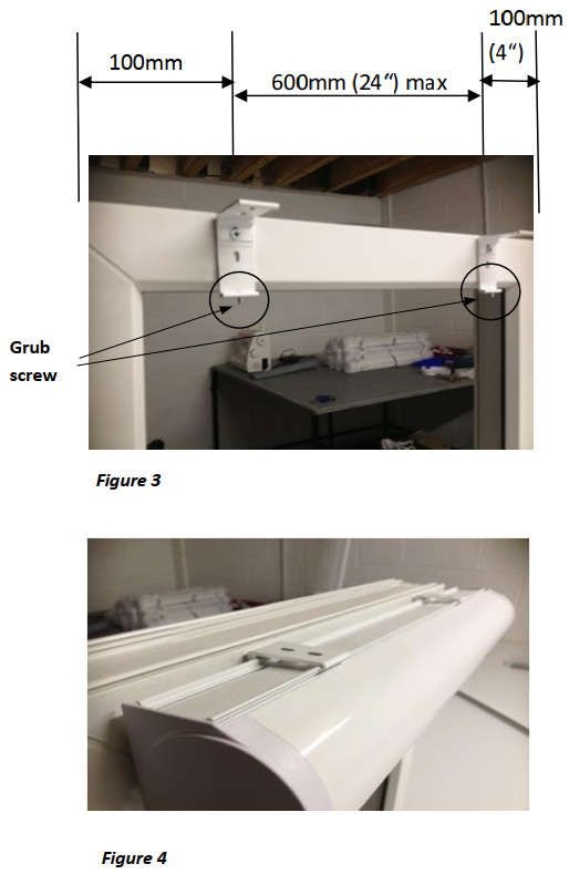
Roller Blind Instruction Manual

Measuring and Options

CEB00XXX-53-000                   Page 8 of 28   Issue 8.2   26 April 2021
Roller Blind Instruction Manual

4.2 Medium Crank-operated Laser Blocking Roller Blind

Dimensions                   Width min.      0.3 m, max.     2.8 m
                             Height max.     3.0 m

Max. Braking Capacity        12.00 kg

Manually Operated Blind      Rod-option designed for fast, smooth, and silent operation.
                             Rod-operated blinds controlled by a detachable crank handle rod.

Cassette Profile             17.5 x 69.5 mm extruded aluminium (Al Mg Si 0,5 F22) fitted on the
                             round end cap of the brackets
Tube Shaft                   Ø36.0 mm steel (0.35 mm K40)
Precision Tube               Ø38.0 / Ø43.0 mm extruded aluminium (Al Mg Si 0,5 F22)
Two-profile Bottom Rail      11.0 x 21.0 mm extruded aluminium (Al Mg Si 0,5 F22)
Round Bottom Rail            Ø15.0 mm

Plastic Parts                High-quality, UV-resistant, temperature-resistant, abrasion-proof

Cord Guiding                 Ø1.0 mm steel cord, plastic-coated, black
Angle of inclination         max. 15°

Operation                    Crank gear box with a reduction of 3:1 and end position adjustment.
                             Crank exit front or backside. Replaceable collapsible handle holder
                             for collapsible handle in 25 and 35 mm.
Operation Side               Optional left or right
Operation Length             1.5 / 2.0 / 2.5 m (or individual)

Fixing                       Adjustable top and bottom stop
Bracket Fixing               wall, ceiling, or reveal
Cord Guiding                 Guide wire fixings can be fitted direct on the frame or underneath.
Colour                       Powder coated white (RAL 9016)

CEB00XXX-53-000                          Page 9 of 28                Issue 8.2     26 April 2021
Roller Blind Instruction Manual

Measuring and Options

CEB00XXX-53-000                   Page 10 of 28   Issue 8.2   26 April 2021
Roller Blind Instruction Manual

4.3 Medium Motorised Laser Blocking Roller Blind

Dimensions                   Width min. 0.45 m,         max.   2.00 m
                             Height max. 1.50 m

Max. Braking Capacity        3.5 - 4.5 kg

Motorised Blind              The roller blind is wound and unwound using an electric motor.
                             The motor can be operated via a switch on the wall or by remote
                             control and permits the exact, stepless positioning of the blind in
                             any desired position.

Cassette Profile             Round 78.0 x 77.5 mm extruded aluminium (Al Mg Si 0.5 F22) fitted
                             on the round end cap of the brackets
Tube Shaft                   Ø27.0 / Ø36.0 mm steel (0.35 mm K40)
Precision Shaft              Ø29.0 / Ø38.0 mm extruded aluminium (Al Mg Si 0.5 F22)
Two-profile Bottom Rail      13.0 x 29.0 mm extruded aluminium (Al Mg Si 0.5 F22)
Round Bottom Rail            Ø15.0 mm

Plastic Parts                High-quality, UV-resistant, temperature-resistant, abrasion-proof

Profile Guiding              The roller blind material extends 20 mm on both sides into the
                             profile guiding
Angle of Inclination         max. 15°

Profile                      Colour matches the cassette colour.
Profile Dimensions           Cross section 46.0 x 26.0 mm
                             Length         max. 4.00 m

Colour                       Powder coated white (RAL 9016)

CEB00XXX-53-000                             Page 11 of 28           Issue 8.2      26 April 2021
Roller Blind Instruction Manual
Motor Operation Roller blind drive motor SOMFY Sonesse 30 RTS
Protection Class II
Protection Index IP 31
Rated Torque 2Nm
Rated Speed 28 rpm
Rated Output Voltage 24VDC
Weight 0.495kg
Tube Diameter 36, 38mm
Length 407mm
Connection 2.5m cable
Connecting Cable 2 x 0.25mm2
Measuring and Options
CEB00XXX-53-000 Page 12 of 28 Issue 8.2 26 April 2021Roller Blind Instruction Manual CEB00XXX-53-000 Page 13 of 28 Issue 8.2 26 April 2021
Roller Blind Instruction Manual

4.4 Large Laser Blocking Roller Blind
    Chain, Crank or Motor-operated
To keep below the maximum hanging weight of 12kg, the maximum area of Orca laser blocking
material is 9sqm using the weight /area of 1.3kg/sqm.

Roller Blind          Width max. 3.00m (see note above)
                      Height max. 3.00m (see note above)

Hanging Weight        max. 12.0 kg
                      (by chain operation with lifting spring)

Operation             Optional left or right
                      Ø4.5 x 6.0 chain
                      Crank operation (white or grey)
                      Motor operation

Operation Height      Chain length = blind height x 0.75
                      Crank length 1.5 / 2.0 / 2.5 m

Colour                Standard white (RAL 9016)
Mounting              Ceiling or wall with universal bracket

Measuring and Options

CEB00XXX-53-000                           Page 14 of 28          Issue 8.2   26 April 2021
Roller Blind Instruction Manual
Profile Guiding
The laser blocking material extends 36mm into the profile guiding. Maximum angle of inclination 15°
Profile Colour Matches the cassette colour.
Dimensions Cross section 70 x 27 (47) mm
Length max. 4.00 m
Note: The roller blind and the profile guiding must be mounted parallel and perpendicular.
CEB00XXX-53-000 Page 15 of 28 Issue 8.2 26 April 2021Roller Blind Instruction Manual 5 Installation Please note, blinds must be fitted by skilled personnel. Any incorrectly installed blind could result in an unsafe installation. Alterations to the blind must be approved by Lasermet. Always use appropriate screws and plugs suitable for the wall or ceiling where the blind is to be fitted. In the interest of safety, for example in hospitals, please adjust pull cords and chains to keep them out of reach of children and/or patients where appropriate and install safety devices such as cleats and cord tidies to limit access to cords. CEB00XXX-53-000 Page 16 of 28 Issue 8.2 26 April 2021
Roller Blind Instruction Manual

CEB00XXX-53-000                   Page 17 of 28   Issue 8.2   26 April 2021
Roller Blind Instruction Manual

CEB00XXX-53-000                   Page 18 of 28   Issue 8.2   26 April 2021
Roller Blind Instruction Manual

CEB00XXX-53-000                   Page 19 of 28   Issue 8.2   26 April 2021
Roller Blind Instruction Manual

5.1 Assembly
Step 1
Carefully unpack the kit and identify the
components shown in Figure 1.

Step 2
Fit the L shaped bracket to the framework
using the face fix or top fix holes. See
Figure 2.

The L shaped brackets should be
positioned 100mm in from either end and
no more than 600mm apart.

Step 3
If the space is greater than 600mm 24” fit
an additional bracket or brackets.

Step 4
Make sure the grub screw is located at
the bottom. See Figures 2 and 3.

Step 5
Locate the top of the cassette into the lip
at the front of the L shaped bracket (see
Figure 4).

Step 6
Push the bottom of the cassette back into
the bottom of the bracket and secure by
turning the grub screw (using a 2mm
Allen key).

CEB00XXX-53-000                               Page 20 of 28   Issue 8.2   26 April 2021
Roller Blind Instruction Manual

Step 7
Position the side guides by offering up
each guide to the cassette, making sure
the edge of the side guide is positioned
on the outside of the cassette end cap.
See Figures 5 and 6

Step 8
Draw a line down a short section of the
side guide on window frame with a
pencil. This is to locate the edge of the
where the spring clip will be fitted.
See Figure 7.

Step 9
Remove the side guide and fasten the
spring clips to the framework as shown in
Figure 8.

Step 10
Repeat this procedure with the guide on
the other side.

Step 11
Locate the edge of the spring clip with the edge of the side guide and
snap into place. Repeat with the other side. See Figure 9.

Spring clips should be positioned no more than 1000mm (36”) apart.

Step 12
Attach the cord tidy in a suitable position to keep the chain stable.

Step 13
Pull the blind to the open position and attach a chain stopper to the
back chain as it enters the end cap.

Step 14
Pull the blind to the closed position and attach a chain stopper to the
front chain as it enters the end cap.

CEB00XXX-53-000                              Page 21 of 28                Issue 8.2   26 April 2021
Roller Blind Instruction Manual

6      Wiring
You must read this before wiring up the power supply to the motor in the motorised roller blind.
Failure to observe and implement the correct wiring as shown will invalidate the warranty and will
destroy the motor.

The wiring must be done by a competent person.

The white wire is the +24VDC from the power supply. The black wire is the negative terminal from
the PSU.

Connect the white wire from the PSU to the Grey/White wire from the roller blind motor.

Connect the black wire from the PSU to the white wire from the roller blind motor.

               If the blind is interlocked, the 4
               interlock wires are coloured red,
               yellow, green and blue and are not
               connected with the motor.

CEB00XXX-53-000                            Page 22 of 28              Issue 8.2      26 April 2021
Roller Blind Instruction Manual
7 Maintenance
Lasermet’s laser blocking roller blinds do not require regular maintenance. There are no
preventative maintenance requirements.
7.1 Cleaning
However, if the unit needs to be cleaned abrasive cleaning materials must not be used as they may
cause damage.
The laser blocking material can be cleaned with soapy water (mild detergent) or it can be cleaned
with Klorosept (or similar — used in hospital environments) using a soft cloth or similar. The laser
blocking material has been tested with Klorosept as described below. Klorosept is therefore
recognised as a safe fluid to use when cleaning Lasermet’s laser blocking roller blind material.
7.2 Laser Blocking Material Test Report
In an in-house study, NaDCC solutions (Klorosept) at concentrations up to 10,000mg/l available
chlorine were used to evaluate the effects of chlorine on the texture, appearance (colour), smell and
weight of Lasermet Laser Blocking Curtain samples.
The Lasermet material which was supplied by Lasermet UK was divided into four equal size pieces
measuring 153 x 168mm approximately and subjected to a range of test parameters as detailed
below.
Note: Soaking of blinds is not a standard practice in hospitals but was used as an extreme worst-
case exposure scenario to exaggerate any possible adverse effects.
CEB00XXX-53-000 Page 23 of 28 Issue 8.2 26 April 2021Roller Blind Instruction Manual
Test Results
No. Conditions Weight Weight Weight Appearance/ Appearance/
before after 2 hours after 24 hours Smell/ Smell/
Texture Texture
after 2 hours after 24
hours
1 Sample wiped 28.1328g 28.1356g 28.1474g No Change No Change
once with
10,000mg/l
solution and left
to dry in air
2 Control Sample 27.8612g 28.7328g 29.8128g No Change No Change
left to soak in
deionised water Allowed to air Allowed to dry
dry for 30 mins completely
= 28.2938g & overnight =
still drying 27.7846g
Returned to
solution.
3 Sample left to 28.4258g 29.3188g 30.8120g No Change No Change
soak in in
1,000mg/l Allowed to air Allowed to dry appearance
solution dry for 30 mins completely or texture.
= 29.0236g & overnight =
still drying 28.4274g Bitter-sweet
odour from
Returned to sample.
solution.
4 Sample left to 28.4198g 29.4652g 31.4662g No Change No Change
soak in in in
10,000mg/l Allowed to air Allowed to dry appearance appearance
solution dry for 30 mins completely or texture. or texture.
= 29.2296g & overnight =
still drying 28.9150g Slight bitter- Slight bitter-
sweet odour sweet odour
Returned to from from
solution. sample. sample.
CEB00XXX-53-000 Page 24 of 28 Issue 8.2 26 April 2021Roller Blind Instruction Manual 8 Programming the Controller for Motorised Blinds CEB00XXX-53-000 Page 25 of 28 Issue 8.2 26 April 2021
Roller Blind Instruction Manual

CEB00XXX-53-000                   Page 26 of 28   Issue 8.2   26 April 2021
Roller Blind Instruction Manual

9       Specifications
Fire Rating      NFP 92-503 M2
                 NFPA 701 Test Method 1
                 ASTM E 84 Class 1 / Class A

Orca Curtain Material

              Irradiated Area                  PEL (T3) 10s               PEL (T2) 100s
                   4 mm2                       3.9 MW/m2                   2.2 MW/m2
                 2000 mm2                      0.62 MW/m2                 0.35 MW/m2

Wolf Curtain Material

              Irradiated Area                  PEL (T3) 10s               PEL (T2) 100s
                   4 mm2                       248 kW/m2                   140 kW/m2
                 2000 mm2                      124 kW/m2                    70 kW/m2

10      Warranty

Lasermet provide a 12-month warranty for defects in materials and manufacture, from the date of
installation or delivery. This warranty covers the laser blocking material on the blind and the
structure of the blind unit. Installations completed by Lasermet are covered against defects in
workmanship for 12 months.

The motor has a five-year warranty on electrically driven blinds. Electrical connections must be made
in accordance with the installation instructions. Any failure to follow these instructions invalidates
the warranty as any incorrect wiring can cause irreparable damage to the motor.

24V motors must be powered using a Somfy transformer. Using any other 24V DC supply will
invalidate the warranty.

Damage or defects caused by other factors are not covered. For example, industrial contamination,
incorrect cleaning, storm damage. Consequential loss is not covered under warranty. Compensation
for indirect or direct loss or damage is expressly excluded. Rectification of the defects or a
replacement does not initiate a new warranty period.

No claims, under the warranty, are valid in the case of minor, technically unavoidable deviations in
colour, patterns or structure or in the case of dimensional deviations of ± 5 mm.

All roller blinds are made-to-measure units. For this reason, cancellation of orders placed and the
return and or exchange of the goods are excluded.

For all deliveries, payments and other legal transactions, English law takes precedence for any
litigation.

CEB00XXX-53-000                                Page 27 of 28           Issue 8.2       26 April 2021
Roller Blind Instruction Manual
11 Contact Details
Lasermet provide a full range of laser interlock equipment including interlock switches, illuminated
warning signs, laser shutters, entry keypads with built-in fail-safe override timer, door locks, external
power supplies etc. which can be interconnected to provide a complete system. We also supply
equipment and consultancy covering all aspects of laser safety. Full support, design, and installation
is available from Lasermet, please contact us for any queries.
For sales and technical support:
Lasermet Ltd.
Lasermet House,
137 Hankinson Road,
Bournemouth
BH9 1HR
United Kingdom.
Tel: +44 (0) 1202 770740
Fax: +44 (0) 1202 770730
Email: sales@lasermet.com
Website: www.lasermet.com
Lasermet Inc.
10N Martingale Road, Suite 400,
Schaumburg, Illinois 60173
United States.
Tel: 847 466 1475
Email: usa@lasermet.com
Website: www.lasermet.com
CEB00XXX-53-000 Page 28 of 28 Issue 8.2 26 April 2021You can also read