Getting Started With TI DLP Display Technology
←
→
Page content transcription
If your browser does not render page correctly, please read the page content below
www.ti.com

Application Report
Getting Started With TI DLP® Display Technology

Juan Alvarez, Jesse Richuso
                                                             ABSTRACT
This application note is a comprehensive quick guide to find important resources for DLP® display products
intended for industrial, enterprise, or personal electronics applications. This document serves as a starting guide
for DLP chipset selection, evaluation, design, and manufacturing. You can benefit from this document regardless
of your experience level and involvement with a DLP display system. You can send feedback or comments on
this document using TI DLP Products E2E support forum.
The maturity of the design and manufacturing ecosystem for DLP display technology allows developers to take
display application concepts to production quickly as illustrated below.

Interested in DLP technology outside of industrial, enterprise, and personal electronics display applications?
Click here for DLP automotive applications and click here for Light Control applications using DLP technology,
such as 3D print, 3D machine vision, and 3D scanning.

DLPA059E – MARCH 2020 – REVISED AUGUST 2021                                                Getting Started With TI DLP® Display Technology   1
Submit Document Feedback
                                              Copyright © 2021 Texas Instruments Incorporated
Table of Contents                                                                                                                                                            www.ti.com

                                                                           Table of Contents
1 Introduction.............................................................................................................................................................................3
2 DLP Display Projection Benefits........................................................................................................................................... 4
3 What is DLP Technology?......................................................................................................................................................6
4 The DLP Display System........................................................................................................................................................7
5 Selecting the Correct DLP Display Chipset....................................................................................................................... 14
6 How to Evaluate Selected DLP Display Chipset................................................................................................................ 17
7 Selecting the Correct Optical Engine..................................................................................................................................18
8 DLP Products Supply Chain................................................................................................................................................ 19
9 Development and Manufacturing........................................................................................................................................ 20
10 Online Resources............................................................................................................................................................... 22
11 Common Display and Projection Terminology................................................................................................................ 23
12 Revision History................................................................................................................................................................. 25

                                                                              List of Figures
Figure 3-1. Digital Micromirror Device......................................................................................................................................... 6
Figure 4-1. Typical DLP Display Block Diagram.......................................................................................................................... 7
Figure 4-2. DLP .2 nHD (DLP2000) Chipset Evaluation Module (EVM) Electronics................................................................... 8
Figure 4-3. Example of a Small Board Design...........................................................................................................................10
Figure 4-4. DLP Pico .23 1080p (DLP230NP) Display Optical Engine...................................................................................... 11
Figure 4-5. .2 WVGA (DLP2010) Optical Module Example....................................................................................................... 12
Figure 5-1. Minimum Target Resolution.....................................................................................................................................15
Figure 6-1. .33 1080p (DLP3310) EVM PC tool DLP IntelliBright Algorithms Screen............................................................... 17
Figure 11-1. Vertical Keystone Correction................................................................................................................................. 23
Figure 11-2. Offset Effect on Projected Image...........................................................................................................................24
Figure 11-3. Throw Ratio Diagram.............................................................................................................................................24

                                                                               List of Tables
Table 1-1. Prioritizing Assistance.................................................................................................................................................3
Table 2-1. DLP Projection Benefits.............................................................................................................................................. 4
Table 2-2. DLP Technology Benefits............................................................................................................................................5
Table 4-1. DLP Display Chipset Nomenclature............................................................................................................................7
Table 4-2. Electronic Components...............................................................................................................................................9
Table 4-3. Optical Components Included in an Optical Module................................................................................................. 13
Table 5-1. Resources Available................................................................................................................................................. 14
Table 7-1. Example Optical Module Specification Table............................................................................................................ 18
Table 10-1. Resources Available............................................................................................................................................... 22
Table 10-2. Popular Resources................................................................................................................................................. 22
Table 11-1. Common Display and Projection Terminology.........................................................................................................23

Trademarks
DLP Pico™, DLP Display LightCrafter™, and DLP IntelliBright™ are trademarks of Texas Instruments.
DLP® is a registered trademark of Texas Instruments.
All trademarks are the property of their respective owners.

2       Getting Started With TI DLP® Display Technology                                                                     DLPA059E – MARCH 2020 – REVISED AUGUST 2021
                                                                                                                                                 Submit Document Feedback
                                                                Copyright © 2021 Texas Instruments Incorporated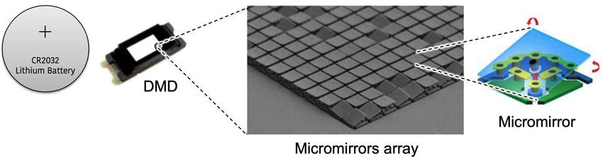
www.ti.com                                                                                                                                                 Introduction

1 Introduction
DLP display products are used in a wide range of traditional accessory projectors and emerging display
equipment. These include embedded projectors in smart phones and tablets, interactive surface computing,
screenless and laser TVs, augmented reality glasses, digital signage, projection mapping, large venue, and
cinema. DLP display technology contains two families of products, DLP Pico™ chipsets and DLP Standard
chipsets. DLP Pico chipsets offer versatile display capability and can create images on virtually any surface from
ultramobile devices. They are a good fit for any application requiring a display with high contrast, small size, and
low power. DLP Standard chipsets enable amazing images for systems that require large screen bright displays
with high resolution.
To help you navigate through this document, we have provided Table 1-1 that can assist you in prioritizing the
sections that you might be interested in.
                                                          Table 1-1. Prioritizing Assistance
 I am...                       Electrical Engineer          Optical Engineer           Software Engineer             Systems Engineer           Portfolio Manager
 New to DLP                •    DLP display projection benefits
 technology
                           •    What is DLP Technology?

 Selecting a DLP chipset   •    What is the DLP       •      What is the display   •    What is the DLP          •    What is the DLP       •    How to select the
                                display electronics          optics system?             display electronics           display electronics        correct DLP display
                                system?               •      How to select the          system?                       and optics system?         chipset
                           •    How to select the            correct DLP display   •    How to select the        •    How to select the
                                correct DLP display          chipset                    correct DLP display           correct DLP display
                                chipset                                                 chipset                       chipset

 Evaluating a DLP chipset •     Chipset evaluation

 Development and           •    Design and Production
 Manufacturing

Refer to Table 1-1 as you move along with your display application development. Visit Getting Started with DLP
Pico technology for a quick reference guide on DLP Pico technology.

DLPA059E – MARCH 2020 – REVISED AUGUST 2021                                                                   Getting Started With TI DLP® Display Technology          3
Submit Document Feedback
                                                          Copyright © 2021 Texas Instruments Incorporated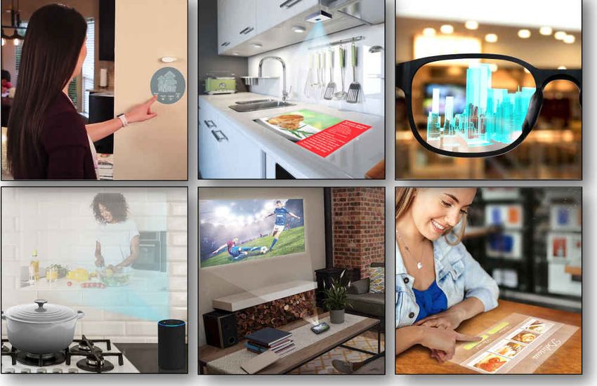
DLP Display Projection Benefits                                                                                                           www.ti.com

2 DLP Display Projection Benefits
Table 2-1 shows the main benefits that DLP projection enables for virtually any display application.
                                                     Table 2-1. DLP Projection Benefits
                Benefit                                                                                      Description

                                                                             Based on the same display technology used in 9 out of 10 cinemas
                                                                             worldwide1, the DLP chipset can enable a display that offers
        Excellent image quality
                                                                             saturated colors and high contrast. Display system performance can
                                                                             vary depending on the optical engine.

                                                                             The reflective technology of DLP technology allows for high contrast
          High contrast ratio                                                as off state mirrors reflect light away from the projection optics
                                                                             creating very black pixels on the display surface.

                                                                             Given its projection nature and high contrast ratio, one can enable
                                                                             a display with virtually any form factor. Black pixels will not show on
          Free form display
                                                                             the display surface (effectively providing a transparent background in
                                                                             those areas).

     Display on virtually any                                                Projection will display on virtually any surface. Warping can be used
             surface                                                         to geometrically compensate for irregular-shaped display surfaces.

                                                                             The DLP technology optical architecture and pixel design allows for
        Small size, large image
                                                                             extremely small-form factors compared to the image displayed.

                                                                             DLP projection display can be turned on and off on demand. The
    Only visible when needed
                                                                             display disappears when it is turned off.

Customers can learn how to promote features enabled by DLP technology by visiting the DLP Products
Messaging and Icons Guidelines document (requires a myTI login).

    1    Based on PMA Research

4        Getting Started With TI DLP® Display Technology                                                DLPA059E – MARCH 2020 – REVISED AUGUST 2021
                                                                                                                             Submit Document Feedback
                                                      Copyright © 2021 Texas Instruments Incorporated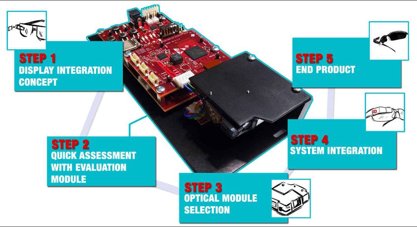
www.ti.com                                                                                                      DLP Display Projection Benefits

DLP technology benefits outlined by application when visiting the web sites shown in Table 2-2.
                                             Table 2-2. DLP Technology Benefits
                 Website                                                        Application Examples
                                          Pico projector, Enterprise portable projector, Laser TV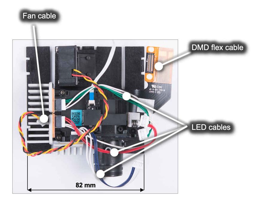
What is DLP Technology?                                                                                                                  www.ti.com

3 What is DLP Technology?
Some developers ask what does DLP stand for. The combination of these three letters do not have any
meaning. DLP technology is the registered trademark brand name of the technology enabled by DMDs. Visit the
Texas Instruments DLP® Brand and Logo Guidelines for additional information.
Texas Instruments DLP technology is a fast-switching micro-electro-mechanical systems (MEMS) technology
that modulates light using a digital micromirror device (DMD) Figure 3-1. DMDs vary in resolution and size
and can contain over 8 million micromirrors. Each micromirror can represent either one or more pixels on a
display. The micromirrors are independently controlled and synchronized with color sequential illumination to
create stunning images on virtually any surface. In some cases, the combination of the speed of the DLP chip,
proprietary algorithms, and an optical actuator located inside the optical engine, can increase pixel density
achieving an effective pixel pitch as small as 2.7μm2.

                                                  Figure 3-1. Digital Micromirror Device

Here is a video that illustrates how DLP technology works to create a stunning image.

    2   2.7μm : 5.4μm TRP pixel node using a 4-way actuator

6       Getting Started With TI DLP® Display Technology                                                DLPA059E – MARCH 2020 – REVISED AUGUST 2021
                                                                                                                            Submit Document Feedback
                                                     Copyright © 2021 Texas Instruments Incorporated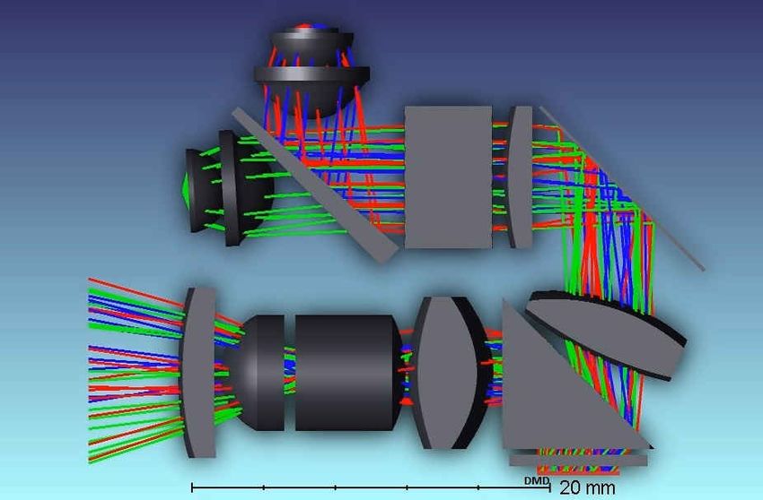
www.ti.com                                                                                                              The DLP Display System

4 The DLP Display System
The display system starts with a video input signal and results in a stunning projected image. A display system
needs three main components to operate: DMD, DLP display controller, and PMIC3. Figure 4-1 illustrates the
typical block diagram of an LED DLP display system. You can also click here for a video that covers the block
diagram of a DLP display system in detail.

                                      Figure 4-1. Typical DLP Display Block Diagram

The display system requires two primary connections: power and data. Power must be supplied to the DLP
PMIC. Digital video data (including 24-bit RGB, DSI, or Vx1) must be supplied to the DLP display controller chip.
A media processor, which accepts external sources like HDMI and processes streamed online content, sends
digital video data out to the DLP display controller. Alternatively, a product's application processor, such as in a
smartphone or tablet, can also send digital video data to the DLP display controller.

Component Part Number Identification
Table 4-1 provides some general guidelines on part number nomenclature for the DLP display chipset.
                                       Table 4-1. DLP Display Chipset Nomenclature
          Component                                                     Part Number Description
                             DMD part number begins with the letters DLP followed by two numbers that represent the active array diagonal
              DMD            in inches. Following digits vary for each unique component.
                             Example: DLP4710, DLP DMD with .47-inch diagonal
                             DLP display controllers begin with the letters DLPC
        Display controller   followed by other digits that vary for each unique component.
                             Example: DLPC3439, DLP Pico .47 1080p display controller
                             DLP PMIC components begin with the letters DLPA followed by other digits that vary for each unique
              PMIC           component.
                             Example: DLPA2000, DLP Pico PMIC supporting up to 200mA of LED drive current

The display system is split up in electronics and optical module hardware.

    3   PMIC : Power management integrated circuit

DLPA059E – MARCH 2020 – REVISED AUGUST 2021                                                  Getting Started With TI DLP® Display Technology   7
Submit Document Feedback
                                                Copyright © 2021 Texas Instruments Incorporated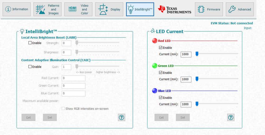
The DLP Display System www.ti.com
Electronics Hardware
The electronics portion of the display system starts with a video input signal (for example, 12/16/18/24-bit RGB
(red, green, blue) parallel, DSI, FPD-Link or Vx1 interfaces, typically driven by an application or media processor.
The output of the electronics portion includes video signal to the DMD commonly using LVDS4 or Sub-LVDS,
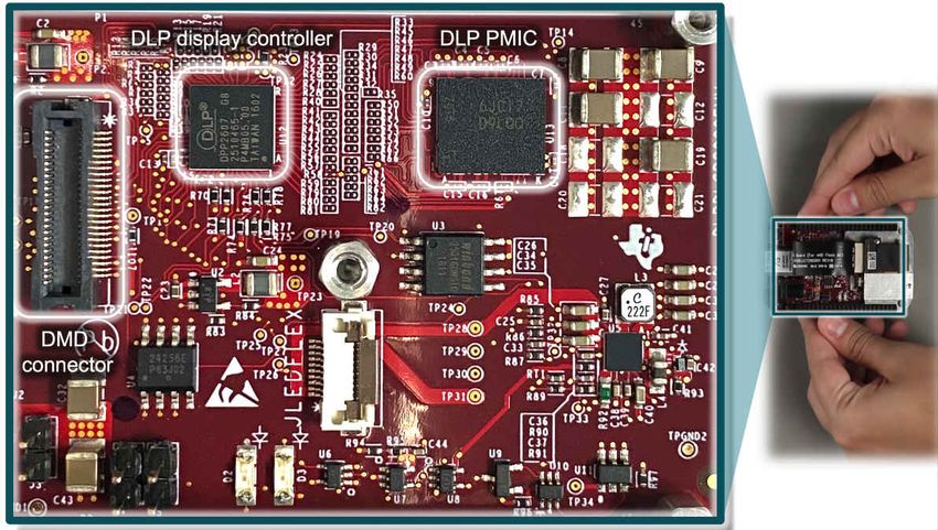
illumination drive, and power. Figure 4-2 shows an example of the electronics hardware.
Figure 4-2. DLP .2 nHD (DLP2000) Chipset Evaluation Module (EVM) Electronics
4 LVDS : Low voltage differential signaling
8 Getting Started With TI DLP® Display Technology DLPA059E – MARCH 2020 – REVISED AUGUST 2021
Submit Document Feedback
Copyright © 2021 Texas Instruments Incorporated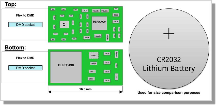
www.ti.com                                                                                                                  The DLP Display System

Table 4-2 includes the components of the electronics portion of the display system.
                                                   Table 4-2. Electronic Components
        Component                                                                 Description
  Applications processor The function of the applications processor is to deliver the video signal to the DLP display system as well as I2C5
                         interface to provide command and control functions. Any video-capable processor should be able to handle this
                         task.
    Display controller       The DLP display controller is the digital interface between the DMD and the rest of the system. The controller
                             takes digital input from an applications processor and drives the DMD over a high speed interface. The DLP
                             controller also generates the necessary signals (data, protocols, timings) required to display images on the DMD.
                             Each display controller has a software user’s guide that details all its supported video handling functions, which
                             will vary depending on the DLP chipset selected. Click here to see an example software programmer’s guide for
                             the .47 1080p DLP Pico chipset (DLP4710).
                             Video signal inputs
                             •   Video interface. The DLP display controller can support a wide range of video interface inputs. 8/16/18/24-bit
                                 RGB parallel interface is most common across the DLP portfolio. In some cases, DSI is supported for
                                 ultra-portable and embedded applications, and Vx1 for 4K resolution. In a few cases, the video interface input
                                 will come from a Field Programmable Gate Array (FPGA)

                                 (In such cases, FPD-Link may be supported).
                             •   I2C is used to command and control the display controller, typically connected from the application processor
                             •   PROJ_ON signal is used to power on/off/reset the display system

                             DMD signal outputs
                             •   DMD video interface. Depending on the chipset, the display controller will commonly output a Sub-LVDS or
                                 LVDS signal to the DMD.
                             •   SPI 6 . Command and control communication with the DLP PMIC (if supported)

                             The display controllers support image processing that helps optimize the image quality displayed, including data
                             compression. A DLP Light Control chipset should be used if precise pixel to pixel mapping is required (typically
                             used in structured lighting applications, learn more here).
                             Image processing features depending on the chipset could include DLP IntelliBright™ algorithms, DLP
                             BrilliantColor™ technology, image keystone correction
                             , warping, blending, frame rate conversion, integrated support for 3-D displays and more.
                             Some systems require dual controllers to format the incoming data before sending it to the DMD.
                             The DMD and its appropriate controller are required to be used together in a system design to ensure reliable
                             operation.
           FPGA              Some chipsets incorporate a technology which creates either two or four pixel images on the screen from a single
                             DMD micromirror. This is accomplished through a combination of proprietary image processing coupled with an
                             optical actuator. The actuator is an opto-mechanical element which is positioned in the optical path between
                             the DMD and the projection lens, and which has the ability to slightly alter the direction of the projection light
                             rays. A 2-way actuator can direct light into two discrete directions, and a 4-way actuator can direct light into four
                             discrete directions. The proprietary image processing converts the image data (from the customers application
                             processor) into either two or four sub-frames of data. These sub-frames of data are then displayed on the DMD,
                             synchronized with the direction-state of the actuator. For chipsets which incorporate this technology, the image
                             processing is performed in an FPGA which sits in the data path between the customers application processor and
                             the DLP controller. This FPGA is designed to receive data in the same manner that a DLP controller would, and
                             generate both the sub-frame data as well as actuator control signals:
                             •   Video interface input from the application processor. Typically RGB parallel, FPD-Link7, or Vx1 interfaces.
                             •   Video interface output and I2C connected to the display controller(s).
                             •   Actuator output drive data (DAC_DATA & DAC_CLK) responsible to drive the actuator wave-form
                                 synchronous with video sub-frames.

    5   I2C : Inter-Integrated Circuit, also referred as I2C
    6   SPI: Serial Peripheral Interface
    7   FPD-Link : Flat Panel Display Link video interface

DLPA059E – MARCH 2020 – REVISED AUGUST 2021                                                      Getting Started With TI DLP® Display Technology     9
Submit Document Feedback
                                                    Copyright © 2021 Texas Instruments Incorporated
The DLP Display System                                                                                                                     www.ti.com

                                              Table 4-2. Electronic Components (continued)
          Component                                                                  Description
     PMIC, LED drive, and      In most cases, a DLP PMIC is responsible for providing input power to the DLP display controller, DMD, and
         motor driver          LED illumination components. The PMIC will take care of supplying core voltages related to the DLP chipset and
                               gently power sequencing the DMD to ensure correct operation.
                               It also provides other monitoring and protection functions, and dynamic LED control based on image color content
                               (for example, DLP IntelliBright algorithms). Integration of the power supply and LED driver circuitry in a small IC
                               not only allows for small-size electronics to be designed, but also reduces the product design cycle time.
                               A motor driver is also needed for systems that include a color wheel. This capability provides a color wheel motor
                               drive control for phosphor laser illumination-based applications, as well as switching regulators and adjustable
                               linear regulators for customer designed peripherals. It supports two peripherals by supplying three fan drivers and
                               one 3-phase BEMF8 motor driver or controller for a color wheel.
          Flash memory         Application-specific configurations are stored in the Flash memory. This component is typically placed on the
                               electronics board or the DMD flex cable.

DLP display controller and PMIC that accompany the DLP Pico DMDs are very small enabling extremely
compact display products. Figure 4-3 shows both sides of an example printed circuit board design (estimate
only) with the DLPA2000 PMIC and the DLPC3430 controller device, which drives a .2 WVGA (DLP2010) DMD.

                                               Figure 4-3. Example of a Small Board Design

Optics
The DMD, along with its associated electronics, an illumination source, optical elements, and necessary
mechanical components, are combined into a compact and rugged assembly known as an optical module or
light engine (Figure 4-4). The optical module is the core display component of the system. Optical modules can
be of various sizes depending on the application and requirements. In general, the higher the brightness, the
larger the size of the optical module due to the use of larger illumination sources, optics, DMDs, and thermal
management components such as heat sinks and fans.
The optics portion of the display hardware system starts with electric signals going into an optical module
housing that include all the components needed to create a projected image. General information about optical
modules are located here for DLP Pico chipsets and here for DLP standard chipsets.
The DMD is connected to the DLP Pico controller by a flex cable or board-to-board connector. The LEDs in
the optical module are connected with wires to the DLP PMIC (LED driver). System boards, fans, heat sinks,
mechanical parts, switches, and other parts are assembled into a compact and robust final product around the
optical module.

      8   BEMF: Back electromotive force

10        Getting Started With TI DLP® Display Technology                                                DLPA059E – MARCH 2020 – REVISED AUGUST 2021
                                                                                                                              Submit Document Feedback
                                                       Copyright © 2021 Texas Instruments Incorporated
www.ti.com The DLP Display System
Figure 4-4. DLP Pico .23 1080p (DLP230NP) Display Optical Engine
DLPA059E – MARCH 2020 – REVISED AUGUST 2021 Getting Started With TI DLP® Display Technology 11
Submit Document Feedback
Copyright © 2021 Texas Instruments IncorporatedThe DLP Display System www.ti.com
Figure 4-5 shows the optical components that can be included in an optical module. Click here to watch a video
of an example optical module reference design (.23 qHD DMD; DLP230GP). Keep in mind that details of an
optical module may not be relevant for a company that is planning to source a mass production optical engine.
For that purpose, click here to read an application note that covers in detail how to specify an optical module.
Also, click here to search for optical modules in mass production available for purchase. Figure 4-5 shows an
optical module design example from this application note.
Figure 4-5. .2 WVGA (DLP2010) Optical Module Example
12 Getting Started With TI DLP® Display Technology DLPA059E – MARCH 2020 – REVISED AUGUST 2021
Submit Document Feedback
Copyright © 2021 Texas Instruments Incorporatedwww.ti.com The DLP Display System
Table 4-3. Optical Components Included in an Optical Module
Components Description
DMD The digital micromirror device is the component that houses the active digital micromirror array, which allows
the creation of a color plane, which enables the projected image in combination with the illumination source.
Each DMD has the following unique characteristics:
• Active array, includes diagonal size of the imager and number of pixels on the imager
• Pixel architecture, includes (a) tilt angle relative to the flat surface, including 12o and, more recently,
17o micromirror tilt; (b) shape of the micromirror including orthogonal and diamond-shaped pixels; (c)
pixel pitch, including 7.6μm or 5.4μm; and (d) illumination direction, including side, bottom, and corner
illumination.
• Video interface, depending on the chipset, a signal provided by the display controller provides the video
data input required to update the active array, including sub-LVDS or LVDS interfaces.
DMD mounting The mounting of the DMD includes several needs: (a) proper placement of the DMD’s active array relative to
mechanism the optical axis of the application, (b) a dust-proof seal between DMD and the optical assembly chassis, (c)
reliable electrical connection, and (d) proper thermal management. Click here to learn more about mounting
concepts for various DLP chipsets.
DMD flex cable Cable used to transport electrical signals between the DMD and the display controller.
Illumination source DLP technology is illumination source agnostic. The illumination sources that are broadly available today are
(color mechanism) RGB LED and laser phosphor.
RGB LED illumination. This illumination scheme uses red, green, and blue LEDs displayed with a single-
color plane refresh rate. In some cases, a fourth LED will be used to increase brightness, although this
brightness increase is penalized heavily against power efficiency. A 3-channel architecture could support
brightness efficiency over 20 lumens/Watt (lm/W), while a 4-channel architecture will support brightness
efficiency lower than 10 lm/W.
Laser phosphor illumination. This illumination approach uses a single blue laser source diffused in
combination with one or two phosphor color wheels to provide RGB light sources. Some implementations
add a red or green channel to boost color performance.
RGB Laser illumination. This illumination approach uses red, green, and blue laser sources. A de-speckler
optical element is typically used for this implemention to improve image quality, although it is not required.
Optical actuator The DMD fast speed allows a use of an optical actuator. 2-way and 4-way actuators that meet TI
(if needed) specifications are used to increase on-screen resolution while retaining the optical benefits of a 5.4μm pixel
node.
2-way actuator, products like the DLP Pico .33 1080p (DLP3310) use a 2-way actuator to double the
on-screen resolution of the DMD active array.
4-way actuator, products like the DLP Standard .47 4K (DLP471TE) use a 4-way actuator to quadruple the
on-screen resolution of the DMD active array
Homogenizer The function of the homogenizer is to make the intensity profile of the light source to be more uniform.
Typically, a fly’s eye array or light tunnel are used for this purpose. The optical element is located between
the illumination source and the DMD.
Projection lens The purpose of the projection lens is to magnify the image coming from the DMD to the display surface. It
also determines the throw ratio, defined as the distance between the projection lens and the display surface
divided by the width of the displayed image. It also determines the image offset of the projection lens relative
to the display surface. Watch this video to learn more about throw ratio and image offset.
Illumination This optical element is responsible to interface between the DMD and projection optics. A few options include
projection interface field lens, non-telecentric, total internal reflection (TIR) prism, and reverse TIR (RTIR) prism.
Thermal management To ensure the proper operation of the optical module, it is important to consider thermal management for the
DMD and the illumination sources. Watch this video to see an innovative example of thermal management for
a very small projection-based smart display.
Watch this video to get more details on common projection lens specifications, including throw ratio definition,
offset definition, and telecentric and non-telecentric architecture comparison.
DLPA059E – MARCH 2020 – REVISED AUGUST 2021 Getting Started With TI DLP® Display Technology 13
Submit Document Feedback
Copyright © 2021 Texas Instruments IncorporatedSelecting the Correct DLP Display Chipset www.ti.com
5 Selecting the Correct DLP Display Chipset
There are several factors to consider selecting the correct chipset. To get started quickly, there are resources
available that you can leverage as shown in Table 5-1.
Table 5-1. Resources Available
Resource Example
See the chipset selection guide to get a comparison of all the DLP
display chipsets available today.
Watch this video to receive some general idea on how to select the
correct chipset for your application.
The following qualifiers should help you down select the DLP chipset that you need for your display application:
Portfolio overview: DLP display products have a wide range offering starting at a nHD resolution supporting 50
lm up to 4K resolution supporting over 10,000 lm. There are two general offerings:
• DLP Standard chipsets. These products are optimal for large displays with high brightness and resolution
requirements ranging from .55 XGA (DLP550JE) resolution to 0.66 4K UHD (DLP660TE) resolution. These
chipsets are also referred as Enterprise and Cinema Display (ECD) chipsets.
• DLP Pico chipsets. With mirror arrays ranging from 0.2-inch to 0.47-inch, DLP Pico products are ideal for
small applications. From nHD (DLP2000) to 4K UHD (DLP471TP) resolutions, DLP microdisplay brings
colorful and crisp images to virtually any surface.
14 Getting Started With TI DLP® Display Technology DLPA059E – MARCH 2020 – REVISED AUGUST 2021
Submit Document Feedback
Copyright © 2021 Texas Instruments Incorporatedwww.ti.com Selecting the Correct DLP Display Chipset
Brightness
Brightness requirement (measured in lumens) varies depending on a range of factors, including image size,
ambient light, and nits. The brightness requirement will affect the diagonal size of the DMD active array. You
can learn more on how to select the right brightness level for your application by reading this application note or
watching this video.
• Brightness vs power consumption, In general, the brighter the projection module, the higher the power
consumption (driven mainly by the illumination power). For embedded applications, a target power of 1 to
2 W is typical, while accessory projectors can range from a few watts to tens of watts. In the case of LED
illumination sources, efficiency is typically not linear, meaning doubling the power to the LEDs results
in less than double the brightness. Finding the right balance of brightness and power consumption is
important.
• Brightness vs size, optical modules can vary greatly in size from a few cubic centimeters in embedded
smartphone or tablet applications to hundreds of cubic centimeters in high brightness accessory projectors. In
general, projection modules with higher brightness capability are larger in size. A larger illumination source,
optics, and DLP DMDs may be used in order to achieve a higher brightness. The power and heat generated
by the illumination source increases as the brightness increases. Heat dissipation requirements add to the
size if heatsinks or fans are necessary. The size of small, low power DLP Pico systems is driven mainly by
the size of the optical module, while the size of larger, higher brightness DLP display systems is driven not
only by the size of the optical module but also the size of the thermal solution.
Resolution
Depending on your application, you will require a minimum resolution to achieve a good image quality on the
display. Figure 5-1 provides a general idea on what resolution is required depending on viewing distance, image
size, and content type.
Figure 5-1. Minimum Target Resolution
DLPA059E – MARCH 2020 – REVISED AUGUST 2021 Getting Started With TI DLP® Display Technology 15
Submit Document Feedback
Copyright © 2021 Texas Instruments IncorporatedSelecting the Correct DLP Display Chipset www.ti.com
Size
You may have very demanding end product size requirements. The size of the optical module, which will
determine the overall physical size of the product, derives from a few considerations including:
1. Brightness level as stated earlier
2. Illumination source
3. f-number, optical system focal length divided by diameter of the entrance pupil (effective aperture)
4. Throw ratio or magnification, the shorter the throw ratio, the larger the optical module due to larger optical
components such as lenses and mirrors
5. Thermal management
16 Getting Started With TI DLP® Display Technology DLPA059E – MARCH 2020 – REVISED AUGUST 2021
Submit Document Feedback
Copyright © 2021 Texas Instruments Incorporatedwww.ti.com How to Evaluate Selected DLP Display Chipset
6 How to Evaluate Selected DLP Display Chipset
After selecting the right chipset for your application, you can purchase a DLP Display LightCrafter™ evaluation
module (EVM). The EVM has a few key features that will help you finalize your chipset and brightness level
selection, and software configuration settings.
• Image quality assessment. The tool provides you with an optical module at a specified brightness level.
Keep in mind that you may find projectors in the market that advertise a specific brightness; you should
measure the brightness of those projectors yourself to verify the measurement of each individual product.
• Modifying chipset software parameters. Most of the EVMs can be used with a PC Windows software
package to make display changes including test patterns/images, color temperature, keystone, DLP
IntelliBright algorithms, and RGB LED current modifications. The PC tool can also update the firmware of
the EVM.
See a screen capture example in Figure 6-1.
Figure 6-1. .33 1080p (DLP3310) EVM PC tool DLP IntelliBright Algorithms Screen
In a few cases, the EVM can connect to a single board computer (SBC) to enable customization of the display
instead of using a PC software. This is the case for the .2nHD (DLP2000) and the .23 1080p (DLP230NP) DLP
Pico chipsets.
• I2C communication. In all cases, I2C is used to command/control the chipset to enable various software
features documented with the chipset’s software users guide. I2C communication can be done directly with
all EVMs. However, each EVM will have its unique requirements on how to do so.
• DLP Pico Firmware selector. For DLP Pico products, you can download a broad selection of firmware
options that will vary depending on the chipset, PMIC, display controller pin-mapping, and application profile.
• Optical module options. You may want to look at various optical module choices for a specific chipset
offering including different levels of brightness, throw ratio, contrast, and optics design. Our optical module
search tool allows you to choose from many optical modules available in the market today. You can contact
the optical module maker to learn more about the module. Seldom a production optical modules can be
connected directly to a DLP EVM. The optical module manufacturer may need to offer you with their own
evaluation tool or instructions how to connect to the TI EVM. Notice the EVM comes rated for a specific LED
current drive, which needs to match with the desired optical module.
DLPA059E – MARCH 2020 – REVISED AUGUST 2021 Getting Started With TI DLP® Display Technology 17
Submit Document Feedback
Copyright © 2021 Texas Instruments IncorporatedSelecting the Correct Optical Engine www.ti.com
7 Selecting the Correct Optical Engine
Optical module selection
There are a lot of optical module choices to select from. It is important that you know exactly what optical module
you need to specify. You can read the application note to understand optical module specifications and other
related system design considerations. After deciding what optical module specification meets your needs, you
should document that specification to share it with optical module maker candidates. All of the terminology used
in the example below are thoroughly explained in the application note.
Table 7-1. Example Optical Module Specification Table
Specification Priority Rank Target Boundary (min/max) Example
Description Provide a high level description of the application and
must-have optical module specifications/features.
Brightness (lumens) > 30 lumens
Resolution (x by y pixels) 854 × 480
Size (x-y-z dimensions in mm) – note if 25 mm × 25 mm × 6 mm
one dimension is higher priority (minimize thickness)
Power consumption (watts) < 1.5 W
Throw ratio 1.0 - 1.5
Offset (typically 0% or 100-120%) 100%
Optional Specifications
Brightness uniformity > 70%
Contrast ratio (full on, full off) > 500:1
Contrast ratio (checkerboard) > 200:1
Optical zoom (note as required or not Not required
required)
Long depth of focus (note as required Not required
or not required)
Focus method (for example, manual, Motorized
motorized, autofocus)
Optical module sourcing
There a few ways to source an optical module. The quickest one, source an optical module that is already in
mass production from an optical module maker. In some cases, you may want to make some modifications to
the optical module. For that case, you can work with an optical module maker to customize a catalog optical
module to meet your needs; the optical module maker may require some commercial terms and conditions
to support you as it may require tooling optical components. If your company has optics expertise, then you
can design the optical module and find a company to manufacture it or manufacture it in-house. Also, you can
contract with a third-party optical engine design house that can design the optical module for you, which can be
manufactured by the design house or an optical module maker.
In some cases, the DMDs will include an optical module design guide that can help you understand the
requirements for that specific chipset.
18 Getting Started With TI DLP® Display Technology DLPA059E – MARCH 2020 – REVISED AUGUST 2021
Submit Document Feedback
Copyright © 2021 Texas Instruments Incorporatedwww.ti.com DLP Products Supply Chain
8 DLP Products Supply Chain
Aligned with the division of hardware electronics and optics, it is common to have the following supply chain
arrangement:
• Texas Instruments designs and supplies DLP chipsets (DMD, controller, and PMIC).
• Optical module maker (OMM) designs the optical system and supplies entire optics housing including the
DMD, illumination source, flex cable, and heatsinks (in some cases).
• System integrator designs the electronics and casing and supplies final product, including optical module
and DLP chipset.
In some cases, the system integrator will design and supply the optical module as well.
DLPA059E – MARCH 2020 – REVISED AUGUST 2021 Getting Started With TI DLP® Display Technology 19
Submit Document Feedback
Copyright © 2021 Texas Instruments IncorporatedDevelopment and Manufacturing www.ti.com
9 Development and Manufacturing
Our experts have consolidated a list that is useful as you move along with your development and ramp of your
display application.
Electrical considerations
• Do not exceed recommended operating conditions
• Choose a flash device memory size by using DLP Composer™ software to create example firmware builds
similar to what you will need in your products.
• Based on your LED voltages and currents needed, select the DLP PMIC that is best suited for use in your
product
• Read all applicable user guides and electrical application notes; follow the guidance given pertaining to the
DLP chipset
• Use TI reference schematic and layout guidelines when designing a PCB using the DLP chipset
Software considerations
• Use DLP Composer software to configure the DLP chipset firmware stored in the flash device as needed by
your product
• Use the software programmer’s guide for the DLP chipset to learn the I2C (or USB) commands that can be
input to control the DLP chipset
• Consider implementing the following image manipulation features integrated in most DLP display controllers:
– 1D keystone correction to vertically compensate the image geometry for a projection engine that is not
perpendicular aligned with the viewing surface.
– DLP IntelliBright™ algorithms for DLPC343x series, CAIC and LABB to increase up to 50% brightness
with the same power or decrease power by 50% without decreasing the brightness.
– Warping and DynamicBlack for DLPC654x and DLPC754x series for compensating the image on irregular
viewing surfaces and enhanced contrast ratio capability.
Optical considerations
• Minimize illumination overfill to reduce heat load on the DMD and maximize light output.
• A light absorber may be required to eliminate or minimize off-state light resulting from thermal or optical
issues.
• Properly manage off-state light for contrast purposes away from projection optics by maintaining the pupil
separation of the illumination and projection light bundles. This is dependent on the DMD pixel architecture,
illumination angle, and F/#.
• TIR or reverse-TIR prisms are effective in separating illumination and projection light in telecentric systems.
Be conscious of the refractive index and ray angles for proper light path transmission.
• In non-telecentric systems, make sure the optical ray angles do not exceed the DMD max ray angles. At high
angles of incidence, the transmission of the DMD window is reduced but also light may be vignetted within
the DMD package apertures. This could produce poor uniformity in the image.
• Depending on the brightness level, be conscious of the optical materials used such as glass vs plastic.
Certain plastic materials may not hold well with high flux density or in high temperatures reducing optical
efficiency, image quality, or both.
Mechanical considerations
• Do not exceed mechanical mounting recommendations
• The DMD data sheet defines thermal and electrical interface areas and the maximum load (force) that can be
applied to each area. Exceeding the maximum load can damage the DMD
• When mounting the DMD the loads applied can be controlled by design, or assembly process.
– Controlled by design is a design where features of the design prevent loads on the DMD that can
exceed the maximum. These typically utilizes shoulder screws and a spring element (flat or coil springs)
– Controlled by assembly is a design that relies on the assembly process to ensure the loads on the DMD
are not exceeded. These typically utilize procedures and torque of screws
– Control by design is the most robust design
20 Getting Started With TI DLP® Display Technology DLPA059E – MARCH 2020 – REVISED AUGUST 2021
Submit Document Feedback
Copyright © 2021 Texas Instruments Incorporatedwww.ti.com Development and Manufacturing
Thermal considerations
• Design to be as cool as practical
• Design the product to meet recommended operating conditions when the DMD is operating. Absolute
maximum ratings are provided as a guide for short term life testing and not long-term operation
• Storage Conditions are always applicable the DMD is not operating. This includes times when before and
after the DMD is installed
• Design the cooling to comprehend the full temperature range the DMD will be used. To help meet the DMD
temperatures in extreme ambient conditions the speed of the cooling fans could be increased, or the optical
power reduced
• Thermal testing early using a thermal mockup before part designs are finalized and tooling started allows
simple changes to be made that can improve thermal performance without impacting schedule or tooling
costs.
• Refine the thermal mockup as the design matures and do additional testing.
• The DMD data sheet identifies specific thermal test point locations that should be used when doing thermal
testing.
• The T_array specification in the DMD data sheet is the calculated array temperature from the identified
thermal test point. A sample calculation is provided in the data sheet.
• Thermal testing of the DMD should be done in the enclosure of the unit. Thermal testing of a standalone
optical module has very different airflow and cooling characteristics which results in very different
temperatures than those in the enclosed unit.
Manufacturing considerations
• Never hot-swap the DMD during assembly
• Follow all power-up and power-down requirements
• Do not over tighten mechanical mounting hardware
• To prevent stress concentration and uneven loads applied to the DMD tighten the mounting screws partially
before final tightening
• Use low power illumination during optical alignment to avoid overheating the DMD aperture or bond line
• DMD temperatures should always be met during assembly (illumination alignment, characterization/testing,
burn-in), storage, and operating
• Exceeding the DMD window temperatures for even a brief period, like illumination alignment, can
permanently damage the DMD that will not be detectable during the manufacturing process
DLPA059E – MARCH 2020 – REVISED AUGUST 2021 Getting Started With TI DLP® Display Technology 21
Submit Document Feedback
Copyright © 2021 Texas Instruments IncorporatedOnline Resources www.ti.com
10 Online Resources
This section is a reference to assist you to quickly identify resources available with the chipset you selected.
DLP Chipset Information
The best method to identify all resources associated with each chipset is to visit the product page of the DMD,
controller, and PMIC of interest. In those pages, you can find information as shown in Table 10-1.
Table 10-1. Resources Available
Component Resources
Data sheet
Product details
• Data sheet highlights
• Packaging
Technical Documentation
• Application-specific technical documents and white papers
DMD • Mounting and electrical interconnect information
• Optical reference design example
• DMD optical efficiency
Design and development
• Chipset evaluation module (EVM) information
• Display system reference designs
Data sheet
Software programmer’s guide
Image calibration
PCB design requirements
Display controller IntelliBright algorithms
Chipset EVM information
Real-time color management reference design
IBIS models
Firmware selector
Data sheet
PMIC
PCB design requirements
Table 10-2. Popular Resources
Resource Description
DLP Pico display getting started website Quick getting started content to help learn, select, evaluate, and develop DLP Pico
display applications
Product selection documents
Product selection video Training that illustrates how to select the right DLP display chipset based on a few
parameters
Chipset selection guide Includes all DLP display chipsets available in mass production
Brightness trade-offs application note and video Provides guidelines on how to select the right brightness level (lumens) for your
application
Optical module selection documents
Common projection lens specifications video Video explaining how a projection system performs and an application note that provides
guidelines on how to specify an optical engine.
OMM search tool Comprehensive mass production-ready optical modules available worldwide
Design resources
E2E forum for DLP Products Forum that you can use to ask questions to our experts as well as review technical
questions that may have already been addressed
PCB design requirements for Standard and Pico Electrical recommendations on how to layout electronics to interface the display
TRP chipsets (myTI login required) controller with the DMD
22 Getting Started With TI DLP® Display Technology DLPA059E – MARCH 2020 – REVISED AUGUST 2021
Submit Document Feedback
Copyright © 2021 Texas Instruments Incorporatedwww.ti.com Common Display and Projection Terminology
11 Common Display and Projection Terminology
Table 11-1 provides common display and projection terminology.
Table 11-1. Common Display and Projection Terminology
Term Description
Brightness Brightness is a measure of how much light is perceived by the human eye in a given scene. This is a function of the amount of light
(number of photons) and their spread across the color spectrum (photon energy), as well as the varying sensitivity of the human eye
across the visible spectrum (most sensitive in the yellow-green region, less sensitive in the blue and red regions). The International
System of Units (SI) identifies the lumen as the unit of measurement for brightness
Lumens A DLP projector will often be specified by the number of lumens it is capable of delivering in its projected image. The brightness
(lumens) determines how large a screen the projector can create and still be viewable in a given ambient light environment. The
greater the brightness, the bigger the displayed image can be made. End products utilizing DLP display technology can range from
20-30 lumens in smartphones and tablets to greater than 50,000 lumens in digital cinema projectors
Contrast The quality of a displayed image is greatly dependent on the distinction between the brightest and the darkest areas of the viewed
image. This is quantified by the contrast ratio, which is the ratio of the brightest possible region of the image to the darkest possible
region of the image. While the contrast ratio specification of a DLP system is based on system performance, the viewing experience
can also be greatly impacted by ambient light. The more ambient light on the screen, the lower the viewable contrast of the image.
Together, system contrast and ambient light determine the true viewable contrast of the image. Special attention must be given to the
optical design, and quality of optics used in the optical module to maximize contrast.
Resolution The level of detail available in an image is determined by the number of pixels which make up the displayed image. In a DLP system,
this is a function of the number of mirrors on the DMD which can represent one or more pixels of the displayed image. Resolution
is the number of pixels that can be displayed. The level of detail displayed is not only dependent on the resolution of the projector
system but it is also dependent on the resolution of the source content. If the resolution of the source content does not match
the resolution of the projector system, the source content is mapped by the controller to make maximum usage of the resolution
displayed. DLP display resolutions range from 640 × 360 (nHD) to 3840 × 2160 (4K UHD).
Keystone When the optical axis of a projection system is not perpendicular to the imaging screen, the image will be geometrically distorted. One
of these distortions, caused by the different distance to the screen top and bottom, is called keystone distortion. The resulting image
will have a different width from top to bottom, giving the image the shape of an architectural keystone (used at the top of an arch).
This distortion can be avoided by keeping the projection axis perpendicular to the screen. However, this is sometimes unavoidable.
The keystone distortion can be corrected optically (very difficult, cost prohibitive, not adjustable) or by image processing means. DLP
controllers provide keystone correction by re-mapping the input image to the DMD array in such a way as to produce a rectangular
image at the screen. The keystone correction feature is commonly paired with an accelerometer in the system to automatically adjust
the image as the projector is tilted up and down.
Figure 11-1. Vertical Keystone Correction
Color sequential display DLP DMDs are made up of micromirrors. They only reflect the light which illuminates them. So, how can a DMD chip reproduce full
color images? The secret is in the way the human eye works. The human retina and brain synthesizes perceived color by means of
a short-term time averaged differential response to the quantity of light impinging on the 3 types of retinal cones (red sensitive, green
sensitive, blue sensitive). Since the eye continuously averages the light striking the retina over a period of about 1/50 second, it is
possible to illuminate the eye sequentially at a sufficient rate with red, green, and blue images such that the viewer perceives the
impression of full color images. This is achieved by a DLP optical module by sequentially turning the R, G, B light sources on and off
such that there is, for example, a red image, followed by a green image, followed by a blue image.
Front projection / rear A DLP display system uses an optical system to produce a real image of the pixel pattern displayed on the DMD. In order for the
projection and screens projected image to be seen by viewers, the light must be scattered off a surface co-located with the plane of image focus. This
function is provided by a screen, which may be a specially optimized sheet of material, or simply a wall, floor, or counter top –
any smooth, light colored surface can make a great image. In a front-projection system, the screen must be a reflective surface. A
rear-projection system requires a translucent, dispersive screen. In both cases the viewer focuses their eyes on the screen in order to
see the projected image. There are some display systems which work by producing a virtual image. For example, near eye displays
and heads-up displays create images that are only formed after the light travels through the eye onto the retina
DLPA059E – MARCH 2020 – REVISED AUGUST 2021 Getting Started With TI DLP® Display Technology 23
Submit Document Feedback
Copyright © 2021 Texas Instruments IncorporatedCommon Display and Projection Terminology www.ti.com
Table 11-1. Common Display and Projection Terminology (continued)
Term Description
Offset The DMD in many DLP projectors is offset to a position below the optical axis of the projection lens in order to shift the image above
the horizontal plane. This is useful when the projector is placed on a table to avoid cutting off the bottom of the projected image. The
offset also avoids the distortion of the image which would occur if the projector was simply tilted up.
Figure 11-2. Offset Effect on Projected Image
Throw ratio In many projection applications, the placement of the projector with respect to the viewing screen is important. The throw ratio of the
projector determines how far away the projector must be placed in order to achieve a certain screen size. The width of the projected
image (W) with respect to the distance from the lens to the center of the screen (D) is the throw ratio (T).
Common references to throw ratio: standard throw: throw ratio>1; short throw (ST): 1>throw ratio>0.4; ultra short throw (UST): throw
ratiowww.ti.com Revision History
12 Revision History
NOTE: Page numbers for previous revisions may differ from page numbers in the current version.
Changes from Revision D (March 2020) to Revision E (July 2021) Page
• Added DLP Display Projection Benefits section................................................................................................. 4
• Updated what is the DLP definition.....................................................................................................................6
• Updated block diagram and added additional details in the section...................................................................7
• Added Selecting the Correct DLP Display Chipset section.............................................................................. 14
• Added How to Evaluate Selected DLP Display Chipset section.......................................................................17
• Updated section to include optical module sourcing section............................................................................ 18
• Added DLP Products Supply Chain section..................................................................................................... 19
• Added Development and Manufacturing section.............................................................................................. 20
• Added Online Resources section..................................................................................................................... 22
• Updated images and added some additional definitions.................................................................................. 23
Changes from Revision C (May 2018) to Revision D (March 2020) Page
• Deleted .65 EXGA and .65 1080p DLP Standard DMDs in the table................................................................. 7
• Updated DLP Standard DMD table.....................................................................................................................7
• Deleted TI Designs............................................................................................................................................. 7
• Added DLP47ONE..............................................................................................................................................7
Changes from Revision B (August 2017) to Revision C (May 2018) Page
• Added the DLP230GP (.23"qHD) and DLP230 KP (.23" HD) to the DLP Display Technology Chipset Selection
Guide.................................................................................................................................................................. 7
Changes from Revision A (January 2017) to Revision B (August 2017) Page
• Updated .2"nHD DMD to DLP2000 and added corresponding links in table...................................................... 7
Changes from Revision * (January 2015) to Revision A (January 2017) Page
• Updated all images and sections........................................................................................................................3
DLPA059E – MARCH 2020 – REVISED AUGUST 2021 Getting Started With TI DLP® Display Technology 25
Submit Document Feedback
Copyright © 2021 Texas Instruments IncorporatedYou can also read