OPERATOR & PARTS MANUAL - Degelman
←
→
Page content transcription
If your browser does not render page correctly, please read the page content below
OPERATOR & PARTS
                                              MANUAL

                                                143397 v1.2

DEGELMAN       INDUSTRIES
BOX 830-272 INDUSTRIAL DRIVE,
                               LP
                                        SCORPION HITCH
REGINA, SK, CANADA, S4P 3B1
FA X 306.543.2140 P H 306.543.4447
                                        REAR TOW HITCH
1.800.667.3545     DEGELMAN.COM      FOR PRO-TILL 33/40
* Reference Sheet Quick-Start Guide
OPERATORS SECTION - TABLE OF CONTENTS
Introduction 1
Safety 2
Detaching / Attaching 4
Air Cart Hook-up 6
Transport 7
Troubleshooting 8
Service & Maintenance 9
PARTS SECTION - TABLE OF CONTENTS
Base / Rear Frame Components 14
Single / Double Shoot Kit Components 16
Mounted / Floating Hose Mounts 17
Rear Tower Mount Kit Components 17
Deflector Mounting Frame Kit - Pro-Till 33 18
Deflector Mounting Frame Kit - Pro-Till 40 19
Secondary Tower Kit Components 20
Primary / Secondary Tower Components 21
Tubing Layout Overview 22
Hydraulic Layout 24
Warranty 25
Maintenance Free Pins & Bushings
IMPORTANT: INSTALL DRY
Do NOT use any oil/grease/lubricant on
pin or bushing surfaces when installing the
maintenance free pins into composite bushings.
DEGELMAN INDUSTRIES LP IMPORTANT:
BOX 830-272 INDUSTRIAL DRIVE,
REGINA, SK, CANADA, S4P 3B1
FA X 306.543.2140 P H 306.543.4447
1.800.667.3545 DEGELMAN.COM
READ MANUALIntroduction
CONGRATULATIONS on your choice of a Degelman PRO-TILL Scorpion Hitch to complement your farming
operation. It has been designed and manufactured to meet the needs of a discerning agricultural market.
Degelman PRO-TILL Scorpion Hitch allows application of seed and fertilizer in conjunction with the high-speed
tillage of the PRO-TILL in a single pass by connecting a tow behind air cart with either single shoot or double
shoot distribution configurations. Use this manual as your first source of information about this attachment.
TO THE NEW OPERATOR OR OWNER - Safe, efficient and trouble free operation of your Degelman PRO-TILL
Scorpion Hitch attachment requires that you and anyone else who will be operating or maintaining it, read
and understand the Safety, Operation, Maintenance and Troubleshooting information contained within this
manual.
By following the operating instructions in conjunction with a good maintenance program your machine will
provide many years of trouble-free service. Keep this manual handy for frequent reference and to pass on to
new operators or owners. Call your Degelman Dealer if you need assistance, information, or additional copies
of the manual.
OPERATOR ORIENTATION - The directions left, right, front and rear, as mentioned throughout the manual,
are as seen from the tractor drivers’ seat and facing in the direction of travel.
LH SIDE RH SIDE
143397 - PRO-TILL HITCH (17-May-2021) -1-Safety
Why is SAFETY important to YOU?
3 BIG Reasons:
•Accidents Can Disable and Kill
•Accidents Are Costly
•Accidents Can Be Avoided
SAFETY ALERT SYMBOL
The Safety Alert Symbol identifies important safety The Safety Alert Symbol means:
messages applied to the PRO-TILL Scorpion Hitch
and in this manual. When you see this symbol, be
ATTENTION!
alert to the possibility of injury or death. Follow the BECOME ALERT!
instructions provided on the safety messages. YOUR SAFETY IS INVOLVED!
SIGNAL WORDS
Note the use of the Signal Words: DANGER, WARNING, and CAUTION with the safety messages.
The appropriate Signal Word has been selected using the following guidelines:
DANGER
DANGER: Indicates an imminently hazardous situation
that, if not avoided, WILL result in death or serious injury
if proper precautions are not taken.
WARNING
WARNING: Indicates a potentially hazardous
situation that, if not avoided, COULD result in death or
serious injury if proper precautions are not taken.
CAUTION: Indicates a potentially hazardous situation
CAUTION that, if not avoided, MAY result in minor or moderate
injury if proper practices are not taken, or, serves as a
reminder to follow appropriate safety practices.
143397 - PRO-TILL HITCH (17-May-2021) -2-Safety
SAFETY GENERAL SAFETY
YOU are responsible for the safe operation and 1. Read and understand the Operator’s
maintenance of your PRO-TILL Scorpion Hitch. Manual and all safety signs before
operating, maintaining or adjusting.
YOU must ensure that you and anyone else who
is going to operate, maintain or work around 2. Install and properly secure all shields and
the PRO-TILL Scorpion Hitch be familiar with the guards before operating. Use hitch pin with a
operating and maintenance procedures and related mechanical locking device.
SAFETY information contained in this manual.
This manual will take you step-by-step through 3. Have a first-aid kit available for use
your working day and alerts you to all good safety should the need arise and know
practices that should be adhered to while operating how to use it.
this equipment.
4. Have a fire extinguisher available
Remember, YOU are the key to safety. Good safety for use should the need arise and
practices not only protect you but also the people know how to use it.
around you. Make these practices a working
part of your safety program. Be certain that 5. Wear appropriate protective gear.
EVERYONE operating this equipment is familiar This list includes but is not limited to:
with the recommended operating and maintenance
procedures and follows all the safety precautions. • A hard hat
Most accidents can be prevented. Do not risk injury
• Protective shoes with slip resistant soles
or death by ignoring good safety practices.
• Protective glasses or goggles
• Heavy gloves
• PRO-TILL Scorpion Hitch owners must • Wet weather gear
give operating instructions to operators
• Hearing protection
or employees before allowing them to
operate the PRO-TILL Scorpion Hitch, and • Respirator or filter mask
at least annually thereafter per OSHA
regulation 1928.51. 6. Clear the area of people, especially small
children, and remove foreign objects from the
• The most important safety device on this machine before starting and operating.
equipment is a SAFE operator. It is the
operator’s responsibility to read and 7. Do not allow riders.
understand ALL Safety and Operating
instructions in the manual and to follow 8. Stop tractor engine, set park brake, remove
these. All accidents can be avoided. ignition key and wait for all moving parts to
stop before servicing, adjusting, repairing or
• A person who has not read and unplugging.
understood all operating and safety
instructions is not qualified to operate the 9. Review safety related items with all operators
machine. An untrained operator exposes annually.
himself and bystanders to possible serious
injury or death.
• Do not modify the equipment in any way.
Unauthorized modification may impair the
function and/or safety and could affect the
life of the equipment.
• Think SAFETY! Work SAFELY!
143397 - PRO-TILL HITCH (17-May-2021) -3-Detaching Scorpion Hitch Rear Frame
DETACHING SCORPION HITCH REAR FRAME 6. The sixth step is to swing the Scorpion Hitch parking
legs down into position. The trick here is to make
The Scorpion Hitch should always be parked on a level, sure that the Scorpion Hitch hydraulic
dry area that is free of debris and foreign objects. The cylinder is NOT fully extended, since the
following procedure outlines how to detach the Scorpion legs would hit the ground if it was.
Hitch rear frame assembly unit from your Pro-Till.
When the Scorpion Hitch is
Follow this procedure to Detach: positioned high enough, the
legs can swing forward
1. The first step in detaching the and the braces can be
Scorpion Hitch is to uncouple unclipped from their
any towed implement from storage positions.
behind the Pro-Till.
Pin the braces into the appropriate holes to hold the
parking legs in the forward position.
7. The seventh step is to fully extend the Scorpion Hitch
hydraulic cylinder, which will lower the tow hitch
2. The second step is to unfold and lower the Pro-Till until the parking legs touch the ground. The clevis
into the working hooks might not fully disengage from the fixed
field position. carrier pins at this point.
8. The eighth step is to lower the
back of the Pro-Till by raising
3. The third step is to extend the Scorpion Hitch hydraulic the packer rollers. If the wheels
cylinder until the Scorpion Hitch parking skid plate across the front are fully lowered,
touches down onto the then the packers can be fully
ground. The objective raised without any worry about
is to balance the hitch the discs touching the ground.
weight and cylinder
9. The ninth step is to drive away if the clevis hooks are
pressure so that the
below and clear of the
force is relieved from
fixed carrier pins.
the locking pins.
4. The fourth step is to disconnect all the "Air Cart to
Scorpion Hitch" quick couplers for the product hoses
and hydraulic hoses. Use caps,
plugs, or covers to prevent dirt
from filling the hose couplers.
5. The fifth step is to remove the IMPORTANT: Once the hitch is fully separated,
Scorpion Hitch locking pins. the Scorpion Hitch cylinder MUST be fully retracted,
A heavy hammer and pry-bar or else there will be damage when folding the
are likely necessary. Slight machine into transport position.
adjustments to the Scorpion The Pro-Till rollers can also be
Hitch hydraulic cylinder lowered to fully raise the
also help to loosen the discs off the ground.
pins for removal.
143397 - PRO-TILL HITCH (17-May-2021)
-4-Attaching Scorpion Hitch Rear Frame
ATTACHING SCORPION HITCH REAR FRAME
The Scorpion Hitch should always be parked on a level, 4. The forth step is to
dry area that is free of debris and foreign objects. The unclip and place
following procedure outlines how to attach the Scorpion the parking leg
Hitch rear frame assembly unit onto your Pro-Till. braces and the
parking legs into
Follow this procedure to attach the Scorpion Hitch Rear
storage position.
Frame to the Mounted Frame :
1. With the Pro-Till unit in field position, the first step is
to extend the Scorpion Hitch Cylinder lowering the
clevis hooks into the proper position to connect to
the rear frame section. Check to ensure the height of
5. The fifth step is to continue
the clevis hooks are low enough to engage the rear
retracting the Scorpion Hitch
frame. May may need to slightly lower the back of
Cylinder until the rear frame
the Pro-Till by raising the packer rollers to accomplish
is fully engaged and properly
this.
positioned to install the
Scorpion Hitch locking pins.
6. The next step is to connect
all the "Air Cart to Scorpion
Hitch" quick couplers for the
product hoses and hydraulic
hoses.
2. The second step is to back-up to the rear frame section, 7. The Scorpion Hitch Rear frame should now be
making sure that the Pro-Till approaches the parked attached and secured to the mounted frame and
hitch as straight as possible. It is difficult for the clevis ready for connecting to an Air Cart.
hooks to pick up the fixed carrier pins if both of them
don’t make contact at the same time.
3. The next step is to retract the Scorpion Hitch hydraulic
cylinder, which will raise the clevis hooks to engage
the fixed carrier pins. When the clevis hooks are
properly engaged, continue to retract the
cylinder until the parking legs are
lifted off the ground.
143397 - PRO-TILL HITCH (17-May-2021) -5-Hook-Up Air Cart
Procedure to Hook-up Scorpion Hitch:
In order to hook-up the detached rear frame of the
Scorpion Hitch, simply reverse the steps listed for the
detaching procedure found on the previous page.
NOTE: One precaution when hooking-up is to make
sure that the Pro-Till approaches the parked hitch as
straight as possible. It is difficult for the clevis hooks
to pick up the fixed carrier pins if both of them don’t
make contact at the same time.
HOOK-UP TO AIR CART HITCH
After the Scorpion hitch has been properly attached and
connected onto the Pro-Till, you can proceed to hook-up
and connect the cart.
1. Using the Scorpion Hitch hydraulic cylinder, adjust
the clevis hitch to the height of the cart hitch, backup
and connect the cart.
2. After the cart has been properly connected, the
Scorpion Hitch Cylinder should be "locked-out".
If there are not enough tractor ports available for it
to remain connected, another option is to disconnect
the cylinder hoses for the Scorpion Hitch. In this
case, the hoses should be capped and secured
properly as not to interfere with the operation of the
Pro-Till.
3. Ensure the Air Cart hitch pin is secured properly
in place. Continue to connect the necessary quick
couplers for the product hoses, hydraulic hoses,
or other necessary Air Cart components for your
specific configuration.
143397 - PRO-TILL HITCH (17-May-2021)
-6-Transport
TRANSPORT SAFETY TRANSPORTING
1. Read and understand ALL the information in Use the following guidelines while transporting:
the Operator’s Manual regarding procedures
1. Use a safety chain and a pin with provisions for
and SAFETY when operating the PRO-TILL in the
a mechanical retainer.
field/yard or on the road.
2. Ensure Pro-Till is in the full transport position with
2. Check with local authorities regarding machine
the wing rollers secure and properly in place.
transport on public roads. Obey all applicable
laws and regulations.
3. Always travel at a safe speed. Use caution when
making corners or meeting traffic.
4. Make sure the SMV (Slow Moving Vehicle) sign,
and all the lights and reflectors that are required
by the local highway and transport authorities
are in place, are clean and can be seen clearly
by all overtaking and oncoming traffic. Be 3. Ensure debris that may fall or become dislodged
sure to check with local highway authorities during transport is removed.
and comply with their lighting and transport
4. Be sure hazard lights are flashing and SMV
requirements.
decal is visible.
5. Keep to the right and yield the right-of-way to
5. MAXIMUM RECOMMENDED TRANSPORT
allow faster traffic to pass. Drive on the road
SPEED: MAX 40 km/h or 25 mph.
shoulder, if permitted by law.
(Road Conditions, Field speeds may be lower.)
6. Always use hazard warning flashers on tractor
Due to weight of the machine and tire ratings,
when transporting unless prohibited by law.
do not exceed the recommended maximum
7. Always use a pin with provisions for a speeds or severe tire damage / excessive wear
mechanical retainer and a safety chain when may occur.
attaching to a tractor or towing vehicle.
6. Check that the transport tires are properly
inflated.
FOLDING INTO TRANSPORT POSITION
IMPORTANT: Under NO
The Scorpion Hitch can be folded into and out-of
transport position using the standard procedure for
CIRCUMSTANCES should there RIDERS
ever be riders while the Pro-Till
the Pro-Till. The first time after the Scorpion Hitch has is in transport.
been installed, you may wish to proceed slowly and
watch carefully to ensure the hoses have been routed
safely and secured properly as not to be pinched,
stretched, or interfere with the folding of the wings.
IMPORTANT
DO NOT Extend
the Hitch Cylinder
During Fold/Unfold, or
Mechanical Damage
Will Occur.
The Scorpion Hitch cylinder is purely for
removing the hitch from the machine and
doing fine adjustments to seeder cart height
and then leaving the hitch at that height.
143397 - PRO-TILL HITCH (17-May-2021) -7-Troubleshooting - Scorpion Hitch
143397 - PRO-TILL HITCH (17-May-2021)
-8-Service & Maintenance
MAINTENANCE SAFETY
1. Review the Operator’s Manual and all safety items
before working with, maintaining or operating the
PRO-TILL.
2. Stop the tractor engine, set park brake, remove
ignition key and wait for all moving parts to stop
before servicing, adjusting, repairing or unplugging.
3. Keep hands, feet, clothing and hair away from all
moving and/or rotating parts.
4. Clear the area of
bystanders, especially
children, when carrying
out any maintenance and
repairs or making any
adjustments.
5. Place safety stands or large blocks under the frame
before removing tires or working beneath the machine.
6. Be careful when working around or maintaining a
high-pressure hydraulic system. Wear proper eye
and hand protection when searching for a high
pressure hydraulic leak. Use a piece of wood or
cardboard as a backstop when searching for a pin
hole leak in a hose or a fitting.
7. Always relieve pressure before disconnecting or
working on hydraulic system.
8. Never disconnect Pro-Till from tractor if rear sections
of machine are partially raised. See warning below:
WARNING/DANGER: Never disconnect Pro-Till
from tractor if rear sections of machine are partially
raised. Negative Hitch Weight may
result, the hitch pole may suddenly
raise and the rear section would come
crashing down. Only disconnect when
unit is on level ground in the proper
transport or field position.
143397 - PRO-TILL HITCH (17-May-2021) -9-Service & Maintenance
HARDWARE SPECIFICATIONS HYDRAULIC SAFETY
Note: Unless stated otherwise, hardware is typically: • Make sure that all components in the hydraulic
Hex, Plated GR5 UNC or P8.8 (metric) system are kept in good condition and are clean.
• Replace any worn, cut, abraded, flattened or
TORQUE SPECIFICATIONS crimped hoses and metal lines.
TORQUE
Checking Bolt Torque • Do not attempt any makeshift repairs to the
The tables below give correct torque values for various bolts hydraulic lines, fittings or hoses by using tape,
and capscrews. Tighten all bolts to the torques specified in clamps or cements. The hydraulic system operates
chart unless otherwise noted. Check the tightness of bolts under extremely high-pressure. Such repairs will
periodically, using these bolt torque charts as a guide. fail suddenly and create a hazardous and unsafe
Replace hardware with the same strength (Grade/Class) bolt. condition.
IMPERIAL TORQUE SPECIFICATIONS • Wear proper hand and eye
(Coarse Thread - based on “Zinc Plated” values) protection when searching for a
high-pressure hydraulic leak. Use
a piece of wood or cardboard as
SAE-5 SAE-8 a backstop instead of hands to
Size Grade 5 Grade 8 isolate and identify a leak.
lb.ft ( N.m ) lb.ft ( N.m )
• If injured by a concentrated high-pressure stream of
1/4” 7 (10) 10 (14) hydraulic fluid, seek medical attention immediately.
5/16” 15 (20) 20 (28) Serious infection or toxic reaction can develop from
3/8” 25 (35) 35 (50) hydraulic fluid piercing the skin surface.
7/16” 40 (55) 60 (80)
1/2” 65 (90) 90 (120) • Before applying pressure to the system, make sure
9/16” 90 (125) 130 (175) all components are tight and that lines, hoses and
5/8” 130 (175) 180 (245) couplings are not damaged.
3/4” 230 (310) 320 (435)
7/8” 365 (495) 515 (700)
1” 550 (745) 770 (1050)
HYDRAULIC HOSE SPECIFICATIONS
1-1/8” 675 (915) 1095 (1485) Note: Unless otherwise stated, Hydraulic Hoses are
1-1/4” 950 (1290) 1545 (2095) either 3/8 or 1/2 with ORF female swivel ends.
1-3/8” 1250 (1695) 2025 (2745)
1-1/2” 1650 (2245) 2690 (3645)
METRIC TORQUE SPECIFICATIONS HYDRAULIC HOSE INSTALLATION TIPS
(Coarse Thread - based on “Zinc Plated” values)
The following tips are to help you identify some possible
problem areas in the installation of hydraulic hoses.
8.8 10.9
1. Installation should be completed in a clean
Size Class 8.8 Class 10.9 environment clear of dust and contaminants.
lb.ft ( N.m ) lb.ft ( N.m ) Hoses and fittings should be capped if not installed.
M6 7 (10) 10 (14)
2. Ensure hoses are not twisted during installation as
M8 16 (22) 23 (31)
this may weaken the hose. Also, the pressure in a
M10 30 (42) 45 (60)
twisted hose may loosen fittings or connections.
M12 55 (75) 80 (108)
M14 90 (120) 125 (170) 3. Allow sufficient bend radius in hoses when installing
M16 135 (185) 195 (265) to prevent lines from collapsing and flow becoming
M18 190 (255) 270 (365) restricted.
M20 265 (360) 380 (515) 4. When installing hoses in an area of movement or
M22 365 (495) 520 (705) flexing, allow enough free length for motion and to
M24 460 (625) 660 (895) ensure fitting connections are not stressed.
M27 675 (915) 970 (1315)
5. Ensure hoses are properly clamped and secured in
M30 915 (1240) 1310 (1780)
position after routing is complete to provide a cleaner
M33 1250 (1695) 1785 (2420)
installation and prevent possible damage or hazards.
M36 1600 (2175) 2290 (3110)
v1.1
143397 - PRO-TILL HITCH (17-May-2021)
-10-Service & Maintenance
HYDRAULIC FITTING INSTALLATION Note: A DASH size refers to a diameter of a hose (inside)
or of a tube (outside) measured in 1/16” increments.
The following info is to help you identify and properly
For example, a Hose specified as dash 8 or -8 would
install some of our standard hydraulic fittings.
have an inside diameter of 8/16” or 1/2”.
SAE (JIC) 37° Flare Alternatively, a Tube specified as dash 8 or -8 would
have an outside diameter of 8/16” or 1/2”.
JIC fittings - Metal-to-metal sealing type fittings featuring
a 37° flare (angle of sealing surface) and straight UNF
(Unified National Fine) Threads. ORB (O-Ring Boss)
(Lubricated Dash Thread Size Torque - lb.ft (N.m) Male ORB fittings have straight UNF threads, a sealing face
Values)
-4 7/16 - 20 9-12 (12-16) and an O-ring. The female fittings are generally found in the
-6 9/16 - 18 14-20 (19-27) ports of machines and feature straight threads, a machined
surface, and a chamfer to accept the O-ring. Sealing is
-8 3/4 - 16 27-39 (37-53)
achieved through the compression of the male O-ring
-10 7/8 - 14 36-63 (50-85)
against the chamfered sealing face of the female fitting.
-12 1-1/16 - 12 65-88 (90-119)
Torque Torque
Tightening JIC 37° Flare Type Fittings (Lubricated Dash Thread Size Non-Adjustable Adjustable
Values)
1. Check flare and flare seat for lb.ft (N.m) lb.ft (N.m)
defects that might cause leakage. 1 -4 7/16 - 20 30 (40) 15 (20)
2. Align fittings before tightening. -6 9/16 - 18 35 (46) 35 (46)
Lubricate connections & hand 2 -8 3/4 - 16 60 (80) 60 (80)
tighten swivel nut until snug. -10 7/8 - 14 100 (135) 100 (135)
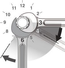
3. Using two wrenches, torque to values shown in table. -12 1-1/16 - 12 135 (185) 135 (185)
Alternate Installation Method Tightening ORB (O-Ring Boss) Fittings
3. Using two wrenches. Place Non-adjustable Port End Assembly
one wrench on the fixed 1. Inspect the components to ensure that male and female
connector body at a clock 4
threads and sealing surfaces are free of nicks, burrs,
position of 6 o’clock. scratches, or any foreign material.
4. Place the second wrench 2. Ensure O-Ring seal is properly installed and undamaged.
on the second connection MIN
3 3. Lubricate threads and O-ring to help the O-ring slide
as close to the 3 o’clock
5 past the port entrance corner and avoid damaging it.
position as possible.
MAX 4. Screw the fitting into position tighten to proper torque
5. Tighten by rotating the
second connection firmly to at least the 4 o’clock position, value from the table shown above.
but no more than the 7 o’clock position. Typically, the Adjustable Port End Assembly
larger the fitting size the less rotation required. Lock Nut
1. Inspect the components to ensure
Back-up
male & female threads and sealing Washer
ORFS (O-Ring Face Seal) surfaces are free of nicks, burrs, O-Ring
ORFS fittings use an O-ring compression method to seal. scratches, or any foreign material.
This method offers a high level of sealing along with good 2. Ensure O-Ring seal is properly installed and undamaged.
vibration resistance. Male fittings include an O-ring located
in a groove on the flat face. Female fittings feature a flat 3. Lubricate threads and O-ring to help the O-ring slide
face and UNF straight threaded swivel nut. smoothly into the port and avoid damage.
The Torque method is recommended for ORFS installation. 4. Loosen back the lock nut as far as possible. Make sure
back-up washer is not loose and is pushed up as far as
Dash Thread Size Torque - lb.ft (N.m)
possible.
-4 9/16 - 18 18 (25)
5. Screw the fitting into port until the back-up washer or the
-6 11/16 - 16 30 (40)
retaining ring contacts face of the port. Light wrenching
-8 13/16 - 16 40 (55)
may be necessary. Over tightening may damage washer.
-10 1 - 14 60 (80)
6. To align the end of the fitting to accept incoming tube
-12 1-3/16 - 12 85 (115)
or hose assembly, unscrew the fitting by the required
Tightening ORFS (O-Ring Face Seal) Fittings amount, but not more than one full turn.
1. Inspect components and ensure the O-Ring seal is 7. Using two wrenches, hold the fitting in desired position
undamaged and properly installed in the groove of the and tighten the locknut to the proper torque value from
face seal. Replacing the O-Ring may be necessary. the table located above.
2. Align, thread into place and hand tighten. 8. Inspect to ensure that O-ring is not pinched and that
3. Tighten to proper torque from the table shown above. washer is seated flat on the face of the port.
143397 - PRO-TILL HITCH (17-May-2021) -11-Service & Maintenance
HYDRAULIC CYLINDER REPAIR
PREPARATION 5. Take the plastic removal ring from the seal kit:
Types of Cylinders a) Straighten the ring and remove any kinks or
When cylinder repair (Wire Ring / Threaded Head)
is required, clean off excessive curl to make installation easier and
unit, disconnect hoses prevent it from falling out.
Wire Ring
and plug ports before b) Insert the removal ring into the internal
removing cylinder. groove with the feathered
end pointing into the tube.
When removed, open
the cylinder ports and
drain the cylinder's 5
hydraulic fluid.
Set Screw
Examine the type of
Threaded
cylinder. Make sure Head
you have the correct
tools for the job.
c) Use a screwdriver or a finger to hold one end
You may require the of the ring in the groove while fitting the other
following tools: end of the ring into the groove. The tips should
• Proper Seal Kit Locking Ring snap in together. Ensure it is secure and fully
• Rubber Mallet seated before the next step.
Threaded
• Screwdriver Head
IMPORTANT: It is important to ensure the
• Punch removal ring is completely in the groove
• Pliers before pulling the rod out. If the ring sticks out
• Emery cloth it will get stuck between the head and tube.
• Torque Wrench
6. a) Extend the rod to pull head out of tube. If the
rod does not pull out easily, push the head back
REPAIRING A WIRE RING CYLINDER in and ensure the ring is properly in the groove.
Replace ring if necessary.
1. Retract the rod assembly.
2. Remove the external steel wire ring.
Inner Wire Ring
2
Initial Ring Positions
6
Plastic Ring
Inner Ring
External Ring
3. Remove any dirt that may have accumulated on Note: Excessive force will not overcome a
the cylinder head. jammed ring and could damage the cylinder.
4. Using the mallet and punch, push the head b) Completely remove rod and head from tube.
into the cylinder tube until the
internal tube groove 7. Remove plastic removal ring from the cylinder
4 is fully exposed. tube.
This will also move the
internal wire ring into
its removal position.
Inner Ring 4
Outer 7
Wire Ring
Internal Groove
(Removed)
v1.0
143397 - PRO-TILL HITCH (17-May-2021)
-12-Service & Maintenance
REPLACING A PRESSED BUSHING STORAGE
NOTE: You may need the following tools: The PRO-TILL should be carefully prepared for
Press, hammer, punch, pry-bar, "Step-Tool" storage to ensure that all dirt, mud, debris and
moisture has been removed.
Use the following as a guideline for repair:
Follow this procedure when preparing to store:
1. Ensure the area and frame are properly secured,
supported, and safe to work on. Safely remove the 1. Wash the entire machine thoroughly using a
pin(s), cylinder, and/or components necessary in water hose or pressure washer to remove all dirt,
order to access and work on the damaged bushing. mud, debris or residue.
2. Remove the existing bushing using required tools. In 2. Inspect all parts to see if anything has become
some instances, you may need to cut the damaged entangled in them. Remove entangled material.
bushing in order for easier removal (use proper 3. Lubricate hub and spindle grease fittings to
safety precautions and try not to damage other remove moisture
components if using this method).
4. Inspect all hydraulic hoses, fittings, lines and
3. With the bushing removed, clean and prepare the couplers. Tighten any loose fittings. Replace any
location for the new bushing insert. Note: A mixture hose that is badly cut, nicked or abraded or is
of "Dish Soap and Water" is recommended to use as separating from the crimped end of the fitting.
a lubricant on the outside of the composite bushing.
5. Touch up all paint nicks and scratches to prevent
IMPORTANT: DO NOT use oil or grease rusting.
on outside or inside of composite bushings.
6. Select an area that is dry, level and free of debris.
4. Use a stepped tool to ensure the edge of the bushing
7. Store in either Transport or Field position.
is not damaged when inserting.
Press (recommended) or
8. Use hydraulic cylinder jack.
Stepped Hammer (to 5/16 depth)
Tool 9. Oil any exposed chrome shafts on the hydraulic
cylinders to prevent rusting.
5/16"
Bushing
Housing
5. Ensuring the bushing is properly aligned, press into
hole (preferred method) or hammer into position by
striking the stepped tool.
6. Continue to install until the bushing edge is recessed
in to a distance of 5/16" to allow for the outer seal
to be properly installed. Do not exceed this depth.
7. Repeat steps 4-6 for opposite bushing (if applicable).
8. When both bushings are installed to the
proper depth, install the new seals. Install
Seal
9. Re-assemble all other
5/16"
necessary components.
IMPORTANT: DO NOT
use oil or grease on pins or
bushing surfaces when re-installing.
143397 - PRO-TILL HITCH (17-May-2021) -13-Base / Rear Frame Components
Base/Rear Frame Overview
142008 - Decal,
Degelman (2)
123119 - Cylinder, CTD
- 4 x 56 x 2-1/2 (1)
142557 - Decal,
142966 - Decal, Reflector
Warning - Pinch Amber (2)
Point (1)
574133 - Rear Frame
Assembly (1)
574073 - Lock Pin Assy (2)
118635 - Flat washer, 2-1/4 (2)
118040 - Bolt, 3/4 x 1-1/2 (2)
574026 - Front Link Support Assembly (1)
comes with...
574046 - Front Link 117416 - Lock Nut, 7/8 Unitorq (1)
Support (1) 118774 - Flat washer, 7/8 - F436 (2)
118767 - Bolt, 7/8 x 3 GR8 (1)
118074
- Bolt, 1 x 573341 - Pin Assy,
4 GR8 (4) 2 x 7-9/16 (1)
574031 - V-Clamp (1) 574048 - Base Frame 117416 - Lock Nut,
Assembly (1) 7/8 Unitorq (2)
118774 - Flat washer,
118911 - Lock 7/8 - F436 (4)
Nut, 1 GRC (4) 118727 - Bolt, 7/8
131020 - Flat x 2-1/2 GR8 (2)
washer, 1 F436 (8)
573341 - Pin
Assembly, 2
x 7-9/16 (2)
574027 - Rear Joint (2) comes with...
Maintenance Free Pins & Bushings
117225 - Bushing, 2-1/2 OD x 2-1/2 (2)
IMPORTANT: INSTALL DRY 133135 - Wiper Seal, 2-1/2 OD (2)
Do NOT use any oil/grease/lubricant on 574047 - Rear Joint Assembly (1)
pin or bushing surfaces when installing the 572891 - V-Clamp (1)
maintenance free pins into composite bushings. 131020 - Flat washer, 1 F436 (2)
118103 - Bolt, 1 x 2-1/2 (2)
143397 - PRO-TILL HITCH (17-May-2021) -14-Base / Rear Frame Components
Rear Frame Components
574009 - Coupler Mount Assembly (1) comes with...
118729 - Lock Nut, 1/2 (4)
574011 - Clamp
118587 - Flat Washer,
Plate (2)
1/2 F436 (8)
118008 - Bolt, 1/2 x 1 (4)
574010 -
Base Plate (1)
mounts with...
118403 - Lock
Nut, 3/8 (4)
118511 - Flat 118005 -
Washer, 3/8 (8) Bolt, 3/8 574113 - Hitch
x 1 (2) Pin (4)
118911 -
574179 - Clevis Hinge
Lock Nut, 1
Assembly (1) 574180 - Clevis Hitch
GRC (1)
Assembly (1)
118115 -
Bolt, 1 x 131020 - Flat washer,
6-1/2 1 F436 (12)
117535 -
GR8 (1) 118911 - Lock 117416 - Lock Nut, Lock Pin (1)
574144 - Nut, 1 GRC (6) 7/8 Unitorq (1)
573342 - Pin
Skid Plate 118774 - Flat washer,
117565 - Bolt, 1 Assembly, 2
Assembly (1) 7/8 - F436 (2)
x 4-1/2 GR8 (6) x 8-5/16 (1)
118767 - Bolt, 7/8 x 3 GR8 (1)
Rear Frame Parking Leg Components
118794 - Bolt, 1/2 x 5 (2)
118729 - Lock Nut,
1/2 Unitorq (2) 574161 - Lock Ring (2)
118901 - Lynch Pin (4)
574023 - Parking Leg
Assembly, LH (1)
574024 - Parking Leg
Assembly, RH (1) 117535 - Lock Pin (2)
142648 - Decal,
Scorpion Hitch (2) 574002 - Stabilizing
Rod (2)
118771 - Nut, 572930 - Handle
7/8 GR8 (2) Grip
118774 - Flat washer,
7/8 - F436 (4)
118727 - Bolt, 7/8
x 2-1/2 GR8 (2)
143397 - PRO-TILL HITCH (17-May-2021) -15-Common Kit Components
Quick Connector Kit Options
Single Shoot - 2.5" (4 Port) Double Shoot - 2.5" (8 Port)
574012 - Quick Connector Kit - 2.5" SS (1) 574013 - Quick Connector Kit - 2.5" DS (1)
Single Shoot - 3.0" (4 Port) Double Shoot - 2.5" (8 Port)
574017 - Quick Connector Kit - 3.0" SS (1) 574018 - Quick Connector Kit - 3.0" DS (1)
Single Shoot Kit Components Double Shoot Kit Components
101000 - Quick Connector 101000 - Quick Connector
Assembly, 2 Port - 2.5 (2) Assembly, 2 Port - 2.5 (4)
- or - - or -
101002 - Quick Connector 101002 - Quick Connector
Assembly, 2 Port - 3.0 (2) Assembly, 2 Port - 3.0 (4)
118292 -
118292 -
Bolt, 1/2 x
Bolt, 1/2 x
1-3/4 (4)
1-3/4 (4)
118417 - Lock
118417 - Lock
Nut, 3/8 (10)
Nut, 3/8 (14)
118511 - Flat 118729 - Lock
118729 - Lock Nut, 1/2 (4) 118587 - 118511 - Flat
Washer, 3/8 (20) Nut, 1/2 (4)
118587 - Flat Flat Washer, Washer, 3/8 (28)
118008 - Bolt, 118005 - Bolt, 118008 - Bolt, 1/2 x 1 (4)
Washer, 1/2 1/2 - F436 118005 - Bolt,
1/2 x 1 (4) 3/8 x 1 (10)
- F436 (16) (16) 3/8 x 1 (14)
574168 - Single Shoot Bracket -LH (1) 574173 - Double Shoot Bracket -LH (1)
574167 - Single Shoot Bracket -RH (1) 574172 - Double Shoot Bracket -RH (1)
574169 - Hose Mounting Plate (2) 574169 - Hose Mounting Plate (2)
574170 - Hose Bracket Clamp (2) 574170 - Hose Bracket Clamp (2)
118729 - Lock Nut, 1/2 (4) 118729 - Lock Nut, 1/2 (4)
143397 - PRO-TILL HITCH (17-May-2021) -16-Common Kit Components
Rear Tower Mount Assembly Components Rear Hitch Floating Hose Mount Components
574158 - Rear Tower Mount Assembly (1) 574114 - Suspended DS Hose Mount Kit (1)
comes with... comes with...
118729 - Lock Nut, 1/2 - Unitorque (8) 101041 - Eyebolt,
1/2 (4)
574096 - Bolt Plate, 3/8 (4)
118512 - Flat Washer, 1/2 (16)
118126 - Bolt, 1/2 x 4 (8)
101048 - Link,
3/8 (4)
574159 - Rear Tower
Mount Assembly -
118512 - Flat Washer, 1/2 (4)
Frame (1)
118729 - Lock Nut, 1/2 (4)
574143 - 101006 - Rope Clamp (2)
Bolt Plate (2)
101045 -
Spring (2)
118083 - Bolt, 3/4
x 7-1/2 (2)
574109 -
Bushing, 1-1/4 574142 - Steel
OD x 1-1/16 (2) 118129 - Bolt, 3/8 x 1-1/4 (4) Rope (2)
117414 - Lock Nut, 3/4
GRC Unitorque (2) 118511 - Flat Washer, 3/8 (8)
118483 - Lock Nut, 3/8 (4)
Rear Hitch Mounted Hose Clamp Assembly FLOATING: 574164 - Rear Hitch Hose Clamp
574175 - Rear Hitch Hose Clamp Assembly - Wide (3) Assembly (3) comes with...
comes with...
118729 - Lock Nut, 1/2 - Unitorque (4)
118417 - Lock Nut, 3/8 (4)
118512 - Flat Washer, 1/2 (4)
118511 - Flat Washer, 3/8 (4)
574165 - Hose Clamp
Bracket (2)
574178 - Hose Bracket
- Wide (1) 574163 - Hose Clamp
Bracket Assembly (2)
101006 - Rope
574176 - Hose Clamp
Clamp Assembly (2)
Assembly - Wide (1)
574162 - Base Plate, 1/4 (1)
Quick Connector Adjustment Assembly
574148 - Quick Connector Adjustment Assembly (1) 4 Port Quick Connector
comes with... as required...
118644 - Bolt, 3/8 x 3 (4)
118511 - Flat 101001 - Quick Connector
Washer, 3/8 (8) Assembly, 4 Port - 2.5
574151 - Quick
Connector Adjustment
Assembly - Frame (1)
118417 - Lock Nut, 3/8 (4)
117414 - Lock Nut, 3/4
118083 - Bolt, 3/4 x GRC Unitorque (2)
7-1/2 (2)
574109 - Bushing, 1-1/4 OD x 1-1/16 (2)
143397 - PRO-TILL HITCH (17-May-2021) -17-Deflector Mounting Frame Kit for Pro-Till 33
Deflector Mounting Frame Kit Components
574149 - Deflector Mounting Frame Kit (1) 574084 - Deflector
comes with... Assembly, 2 Outlet - LH (2)
574085 - Deflector
Assembly,
2 Outlet - RH (2)
574129 - Deflector Assembly,
Wing Frame - 5 Outlet - RH (1)
574128 - Deflector Assembly,
Wing Frame - 5 Outlet - LH (1)
574130 - Deflector Assembly,
Wing Frame - 7 Outlet (2)
574080 - Deflector Assembly,
Kit Mounting Components
Center Frame - 8 Outlet (1)
118014 - Bolt, 1/2
x 2 (36) 574081 - Deflector Assembly,
118587 - Flat Washer, Center Frame - 12 Outlet (1)
1/2 - F436 (72)
574124 - V-Clamp (18)
118729 - Lock Nut, 1/2 (36)
Deflector Mounting Frame Location Overview - 33'
A B C
G
E
J
D F H K
*Distances Measured from
Tube Wall to Clamp Edge
A - 24-11/16" (574130)
(Need to B - 13-7/16" (574081)
check 33' C - 24-11/16" (574130)
Pro-Till Position
Dimensions) D - 24-3/4" (574085)
E - 28-1/2" (574129)
F - 6-3/8" (574085)
G - 11-5/16" (574080)
H - 13-1/2" (574084)
J - 20-3/8" (574128)
K - 29-3/8" (574084)
143397 - PRO-TILL HITCH (17-May-2021) -18-Deflector Mounting Frame Kit for Pro-Till 40
Deflector Mounting Frame Kit Components 574084 - Deflector Assembly,
2 Outlet - LH (2)
574150 - Deflector Mounting Frame Kit (1)
comes with...
574085 - Deflector
Assembly,
2 Outlet - RH (2)
574082 - Deflector Assembly,
Wing Frame - 8 Outlet (2)
574080 - Deflector Assembly,
Center Frame - 8 Outlet (1)
574081 - Deflector Assembly,
Center Frame - 12 Outlet (1)
Kit Mounting Components 574083 - Deflector Assembly,
118014 - Bolt, 1/2 Wing Frame - 10 Outlet (2)
x 2 (44)
118587 - Flat Washer,
1/2 - F436 (88)
574124 - V-Clamp (22)
118729 - Lock Nut, 1/2 (44)
Deflector Mounting Frame Location Overview - 40'
A B C
G
E
J
D F H K
*Distances Measured from
Tube Wall to Clamp Edge
A - 17-1/2" (574083)
B - 13-7/16" (574081)
C - 11-1/4" (574083)
D - 24-3/4" (574085)
E - 21-5/8" (574082)
F - 6-3/8" (574085)
G - 11-5/16" (574080)
H - 13-1/4" (574084)
J - 21" (574082)
K - 29-3/8" (574084)
143397 - PRO-TILL HITCH (17-May-2021) -19-Common Kit Components
Secondary Tower Kit Components
574087 - Secondary Tower Mounting Kit (1) 574142 - Secondary Riser Clamping Kit (1)
comes with... comes with...
101046 - U-Bolt,
Clamp (24)
574089 - Distribution
Tower Bracket
- STD (6)
101027 - U-Bolt, 1/2 574127 - Distribution
UNC (16) Tower Bracket
- Notched (2)
118729 - Lock Nut, 1/2 - Unitorque (32)
118587 - Flat Washer, 1/2 - F436 (32)
Secondary Tower Bracket Location Overview - 33'
A C D H
B E F G
Note: Distances
Measured from
Tube Wall Unless
Noted Otherwise
A - 11" (574089) E - 11-1/2" (574089) (Distances
B - 19-1/2" (574089) F - 11-1/2" (574089) Measured from
Lug Plate)
C - 6" (574127) G - 12" (574089)
D - 3/4" (574127) H - 3" (574089)
Secondary Tower Bracket Location Overview - 40'
A C D H
B E F G
Note: Distances
Measured from
Tube Wall Unless
Noted Otherwise
A - 5" (574089) E - 11-1/2" (574089) (Distances
B - 3" (574089) F - 11-1/2" (574089) Measured from
Lug Plate)
C - 6" (574127) G - 3-3/4" (574089)
D - 3/4" (574127) H - 4-3/4" (574089)
143397 - PRO-TILL HITCH (17-May-2021) -20-Common Kit Components
Primary Tower Components
Riser Head Cap
101034 - Riser
101037 - Riser Head, Primary 101057 - Replacement
Head, Primary 6.0 - 8 Port x 2.5 Cap, 10.125 OD (1)
5.0 - 8 Port x 2.5
101035 - Riser 101058 - Replacement
101038 - Riser Head, Primary Rubber Cap, 10.125 OD (1)
Head, Primary 6.0 - 4 Port x 2.5
5.0 - 4 Port x 2.5
101036 - Riser
101039 - Riser Head, Primary
Head, Primary 6.0 - 4 Port x 3.0
5.0 - 4 Port x 3.0
101029 - Riser, Primary - 6.0
101028 - Riser, Primary - 5.0
Secondary Tower Components 101018 - Riser,
Secondary - 3.0
101009 - Riser, 101019 - Riser
Secondary - 2.5 Head, Secondary
2.5 - 6 Port
101005 - Y- Adapter, 3 to 2 x 2.5 101024 - Riser
Head, Secondary
101004 - Y- Adapter,
2.5 - 7 Port
2.5 to 2 x 2.5
101003 - Single
101026 - Riser
Adapter, 3.0 to 2.5
Head, Secondary
3.0 - 8 Port
Secondary Tubing 574115 - 40' Hose Clamp Kit (1)
101049 - Air Seeder Hose - 3" x 100' Roll (model specific) comes with...
101050 - Air Seeder Hose - 2.5" x 100' Roll (model specific) 101044 - Hose Clamp,
up to 2 (128)
101043 - Hose Clamp,
Tertiary Tubing up to 3-1/2 (32)
101051 - Air Seeder Hose - 1.5" x 100' Roll (4)
574196 - 33' Hose Clamp Kit (1)
comes with...
101044 - Hose Clamp,
up to 2 (104)
246992 - Hose Clamp,
up to 2-1/2 (40)
143397 - PRO-TILL HITCH (17-May-2021) -21-Tubing Layout Overview
Riser Head Location & Grouping Overview - 33' Layout
7
7 6 6
6 6
7 7
Riser Head Location & Grouping Overview - 40' Layout
8 8 8 8
8 8 8 8
Tubing Layout Example (on Pro-Till 40)
143397 - PRO-TILL HITCH (17-May-2021) -22-Tubing Layout Overview
Tubing Layout Example - LH Wing (on Pro-Till 40) Tubing Installation Overview
• Tubing is provided in large rolls for both
secondary (2.5" or 3") and tertiary (1.5")
distribution routing. Tubing is to be routed
and cut-to-length as needed.
• When routing both secondary and tertiary
tubing, the tubing must be secured out
of the way to prevent being pinched or
damaged when folding the Pro-Till into or
out of transport position.
• Secondary tubing (2.5"
or 3") are secured with
the large 101043 Hose
clamps and the tertiary
(1.5") tubing are secured
with the smaller 101044
Hose clamps.
Tubing Layout Example - Transport (on Pro-Till 40)
143397 - PRO-TILL HITCH (17-May-2021) -23-Hydraulic Layout
Hydraulic Fittings Required 1 1 141581 - Coupler Tip,
2 2 3/4 ORB F (2)
1 141581 - Coupler Tip, 3/4 ORB F (2)
2 141676 - Connector, 3/4 ORB M x M (2) 4 3 141676 - Connector,
141681 3/4 ORB M x M (2)
3 141680 - Coupler, Grey (+) (1) 5 5 – Coupler,
141680 - Coupler,
4 141681 - Coupler, Grey (-) (1) Grey (-) (1) Grey (+) (1) +
5 141703 - Adaptor, 1/2 ORB M x ORFS M (2)
141703 - Adaptor, 1/2
6 141704 - Elbow, 90º 1/2 ORB M x ORFS M (2) ORB M x ORFS M (2)
Required Hoses for Transport Cylinders
360 126798 - Hose, 3/8 x 148 (1)
420 126799 - Hose, 3/8 x 188 (1)
420 360
420 360
117225 - Bushing, 2-1/2 OD x 2-1/2 (4)
133135 - Wiper Seal, 2-1/2 OD (4)
123119 - Cylinder, CTD - 4 x 56 x 2-1/2 (1)
(Seal Kit: 123168)
Previous: 123111 - Cylinder, CTD - 4 x 56 x 2 (1)
(Seal Kit: 123028)
6
6
Maintenance Free Pins & Bushings
IMPORTANT: INSTALL DRY
Do NOT use any oil/grease/lubricant on
pin or bushing surfaces when installing the
maintenance free pins into composite bushings.
143397 - PRO-TILL HITCH (17-May-2021) -24-Warranty
2 Year
Limited Warranty - Agricultural Products
Degelman Industries LP (“Degelman”) warrants to the original purchaser of any new Degelman equipment, purchased
from an authorized Degelman dealer, that the equipment will be free from defects in material and workmanship for a
period of two (2) years from the date of delivery, for non-commercial use (including farm, institutional, government, and
municipality) and (1) year from the date of delivery for commercial use. The obligation of Degelman to the purchaser
under this warranty is limited to the repair or replacement of defective parts in the first year and to the provision, but not
the installation of replacement parts in the second year. Degelman reserves the right to inspect any equipment or parts
which are claimed to have been defective in material or workmanship.
This warranty limits its replacement or repair coverage to what is consistent with the warranty of Degelman’s suppliers of
purchased components.
Replacement or repair parts installed in the equipment covered by this limited warranty are warranted for ninety (90)
days from the date of delivery of such part or the expiration of the applicable new equipment warranty period, which ever
occurs later. Warranted parts shall be provided at no cost to the user at an authorized Degelman dealer during regular
working hours. Warranted replacement parts will either be replaced or rebuilt at Degelman’s discretion.
Disclaimer of implied warranties & consequential damages
This warranty shall not be interpreted to render Degelman Industries LP liable for injury, death, property damage or
damages of any kind, whether direct, consequential, or contingent to property. Without limiting the generality of the
foregoing, Degelman shall not be liable for damages resulting from any cause beyond its reasonable control, including,
without limitation, loss of crops, any expense or loss of labour, supplies, rental machinery or loss of use.
No other warranty of any kind whatsoever, express or implied is made with respect to this sale; and all implied warranties
of merchantability and fitness for a particular purpose which exceed the obligations set forth in this written warranty are
hereby disclaimed and excluded from this sale. This exclusion shall not apply in any jurisdiction where it is not permitted
by law.
This limited warranty shall not apply:
1. If, in the sole opinion of Degelman, the unit has been subjected to misapplication, abuse, misuse, negligence
accident or incorrect off-site machine set-up.
2. To any goods that have sustained damage or deterioration attributable to a lack of routine maintenance (eg. Check
and Re-torque of fastening hardware, Hydraulic fluid purities, drive train alignments, and clutch operation)
3. If parts not made or supplied by Degelman have been used in the connection with the unit, if, in the sole judgement
of Degelman such use affects its performance, safety, stability or reliability.
4. If the unit has been altered or repaired outside of an authorized Degelman dealership in a manner which, in the sole
judgement of Degelman, affects its performance, safety, stability or reliability.
5. To expendable or wear items such as (eg. Harrow tines, Rock Picker and Rock Rake wear teeth and replaceable
bushings and pins.) and any other items that in the company’s sole judgement are a wear item.
No employee or representative of Degelman Industries LP is authorized to change this limited warranty in any way or
grant any other warranty unless such change is made in writing and signed by the Degelman Service Manager.
This limited warranty is subject to any future availability of supply, which may directly affect Degelman’s ability to obtain
materials or manufacture replacement parts.
Degelman reserves the right to make improvements in design or changes in specifications at any time, without incurring
obligations to owners of equipment previously delivered.
This limited warranty is subject to compliance by the customer to the enclosed Retail Customer’s Responsibility Under
Degelman Warranty.
143397 - PRO-TILL HITCH (17-May-2021) -25-Warranty
Retail Customer’s Responsibility Under Degelman Warranty.
It is the retail customer and/or Operator’s responsibility to read the Operator’s Manual, to operate, lubricate, maintain
and store the equipment in accordance with all instructions and safety procedures. Failure of the operator to read the
operators manual is a misuse of this equipment.
It is the retail customer and/or operators responsibility to inspect the product and to have any part(s) repaired or replaced
when continued operation would cause damage or excessive wear to other parts or cause safety hazard.
It is the retail customer’s responsibility to deliver the product to the authorized Degelman dealer, from whom he purchased
it, for service or replacement of defective parts, which are covered by warranty. Repairs to be submitted for warranty
consideration must be made within forty-five days of failure.
It is the Retail Customer’s responsibility for any cost incurred by the dealer for hauling of the product for the purpose of
performing a warranty obligation or inspection.
WARRANTY INFORMATION
Make certain the warranty registration card has been forwarded to: Degelman Industries LP
Box 830 -272 Industrial Dr.
Regina, SK, Canada
S4P 3B1
Always give your dealer the serial number of your Degelman product when ordering parts or requesting
service or other information.
The serial number is located on the machine as shown in the diagram below. In the space provided record the
model number, the serial number and the date of purchase to assist your dealer in providing you with prompt
and efficient service.
SERIAL NUMBER:
MODEL NUMBER:
DATE OF PURCHASE:
143397 - PRO-TILL HITCH (17-May-2021) -26-You can also read