THOR Electric piston pump
←
→
Page content transcription
If your browser does not render page correctly, please read the page content below
ED. 16 - 02/2020

                         w w w. l a r i u s . c o m

                                                         THOR
      Cod. 150096

                                                      Electric piston pump
OPERATING INSTRUCTIONS

                                                          English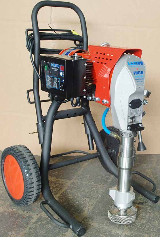
This manual is to be considered as an English language translation of the original manual in Italian.
The manufacturer shall bear no responsibility for any damages or inconveniences that may arise due to
       the incorrect translation of the instructions contained within the original manual in Italian.

      Due to a constant product improvement programme, the factory reserves the right to modify
                    technical details mentioned in this manual without prior notice.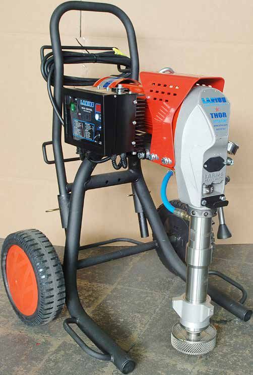
THOR

                                                                            THOR
                                                                        Electric piston pump

       WARNINGS........................................................... p.2                  Checking the seal gasket (o-ring)...................... p.23
A WORKING PRINCIPLE.......................................... p.3                                Reduction box greasing.................................... p.24
B TECHNICAL DATA................................................. p.4                   L PROBLEMS AND SOLUTIONS............................. p.25
C DESCRIPTION OF THE EQUIPMENT................... p.5                                   M CORRECT PROCEDURE OF
           Alarm messages............................................... p.7                 DECOMPRESSION............................................... p.26
           Functions table................................................. p.7         N REPLACEMENT OF THE PUMPING
           Alarm message table........................................ p.8                   GROUP’S GASKETS............................................. p.27
D TRANSPORT AND UNPACKING........................... p.8                                         Pit stop maintenance........................................ p.28
E SAFETY RULES..................................................... p.9                          Lower seal......................................................... p.28
           Electrical safety precautions............................. p.10                       Upper seal......................................................... p.30
 F SETTING-UP......................................................... p.10             SPARE PARTS
           Connection of the flexible hose to the gun....... p.10                       O COMPLETE ELECTRO-MECHANICAL
           Check on power supply.................................... p.10                    UNIT...................................................................... p.36
           Connection of the tooling to the power                                       P COMPLETE LONG PUMP UNIT............................ p.38
           supply............................................................... p.12   Q SHORT PUMP UNIT FOR STANDARD
           Washing of the new equipment........................ p.12                         PRODUCTS........................................................... p.40
           Preparing the product....................................... p.13            R Filter assembly............................................... p.42
G WORKING............................................................. p.14             S SUCTION AND CIRCULATION UNIT FOR
           Start of the working operations........................ p.14                      STANDARD PRODUCTS....................................... p.43
           Spray adjustment.............................................. p.16          T PRESSURE CONTROL DEVICE............................ p.44
H CLEANING AT THE END OF THE WORK.............. p.16                                    U TROLLEY............................................................... p.46
           Cleaning for solvent-based products............... p.16                      V    ELECTRICAL CONTROL ...................................... p.47
           Cleaning for water-based products.................. p.20                     W    ELECTRIC MOTOR............................................... p.48
 I ROUTINE MAINTENANCE.................................... p.22                         X    ELECTRICAL DIAGRAM........................................ p.49
           Check on the packing nut................................. p.22               Y    ACCESSORIES...................................................... p.51
           Checking the heat exchange radiator............... p.23                      Z    VERSIONS............................................................. p.57

                                    WE ADVISE THE USE OF THIS EQUIPMENT ONLY BY PROFESSIONAL OPERATORS.
                                   ONLY USE THIS MACHINE FOR USAGE SPECIFICALLY MENTIONED IN THIS MANUAL.

                                                Thank you for choosing a LARIUS S.R.L. product.
                                 As well as the product purchased, you will receive a range of support services
                                    enabling you to achieve the results desired, quickly and professionally.

ED. 16 - 02/2020 - Cod. 150096                                                                                                          www.larius.com                  1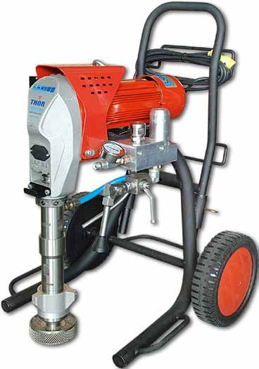
THOR

WARNINGS
The table below provides the meaning of the symbols used in this manual in relation to using, earthing, operating, maintaining, and
repairing of this equipment.

          • Read this operator’s manual carefully before using the equipment.
          • An improper use of this machine can cause injuries to people or things.
          • Do not use this machine when under the influence of drugs or alcohol.
          • Do not modify the equipment under any circumstances.
          • Use products and solvents that are compatible with the various parts of the equipment, and read the manufacturer’s warnings carefully.
          • See the Technical Details for the equipment given in the Manual.
          • Check the equipment for worn parts once a day. If any worn parts are found, replace them using ONLY original spare parts.
          • Keep children and animals away from work area.
          • Comply with all safety standards.

          • It indicates an accident risk or serious damage to equipment if this warning is not followed.

          FIRE AND EXPLOSION HAZARD
          • Solvent and paint fumes in work area can ignite or explode.
          • To help prevent fire and explosion:
             - Use equipment ONLY in well ventilated area.
             - Eliminate all ignition sources, such as pilot lights, cigarettes and plastic drop cloths (potential static arc).
             - Ground equipment and conductive objects.
             - Use only grounded hoses.
             - Do not use trichloroethane, methylene chloride, other halogenated hydrocarbon solvents or fluids containing such solvents in
                pressurized aluminium equipment. Such use can cause serious chemical reaction and equipment rupture, and result in death,
                serious injury, and property damage.
             - Do not form connections or switch light switches on or off if the air contains inflammable fumes.
          • If electrical shocks or discharges are encountered the operation being carried out using the equipment must be stopped immediately.
          • Keep a fire extinguisher at hand in the immediate vicinity of the work area.
          • It indicates wound and finger squashing risk due to movable parts in the equipment.
          • Tenersi lontano dalle parti in movimento.
          • Do not use the equipment without the proper protection.
          • Before any inspection or maintenance of the equipment, carry out the decompression procedure explained in this manual, and prevent
            any risk of the equipment starting unexpectedly.
          • Report any risk of chemical reaction or explosion if this warning has not been given.
          • (IF PROVIDED) There is a risk of injury or serious lesion related to contact with the jet from the spray gun. If this should occur,
             IMMEDIATELY contact a doctor, indicating the type of product injected.
          • (IF PROVIDED) Do not spray before the guard has been placed over the nozzle and the trigger on the spray gun.
          • (IF PROVIDED) Do not put your fingers in the spray gun nozzle.
          • Once work has been completed, before carrying out any maintenance, complete the decompression procedure.

          • It indicates important recommendations about disposal and recycling process of products in accordance with the environmental
             regulations.
          • Mark any clamps attached to earth cables.
          • Use ONLY 3-wire extension cords and grounded electrical outlets.
          • Before starting work make sure that the electrical system is grounded and that it complies with safety standards.
          • High-pressure fluid from gun, hose leaks, or ruptured components will pierce skin.
          • To help prevent injection, always:
             - (IF PROVIDED) Engage trigger lock when not spraying.
             - (IF PROVIDED) Do not put your hand over the spray tip. Do not stop or deflect leaks with your hand, body or other.
             - (IF PROVIDED) Do not point gun at anyone or at any part of the body.
             - (IF PROVIDED) Never spray without tip guard.
             - Do pressure relief if you stop spraying or being servicing sprayer and before any maintenance operations.
             - Do not use components rated less than sprayer Maximum Working Pressure.
             - Never allow children to use this unit
             - (IF PROVIDED) Brace yourself; gun may recoil when triggered.
          If high pressure fluid pierces your skin, the injury might look like “just a cut”, but it is a serious wound!
          Get immediate medical attention.

          • It is obligatory to wear suitable clothing as gloves, goggles and face shield.
          • Wear clothing that complies with the safety standards in force in the country in which the equipment is used.
          • Do not wear bracelets, earrings, rings, chains, or anything else that may hinder the operator’s work.
          • Do not wear clothing with wide sleeves, scarves, ties, or any other piece of clothing that could get tangled up in moving parts of the
            equipment during the work, inspection, or maintenance cycles.

 2     www.larius.com                                                                                                      ED. 16 - 02/2020 - Cod. 150096
THOR

 A      WORKING PRINCIPLE
The THOR unit is defined “electric piston pump”.                           sent to the gun through the flexible hose.
An electric piston pump is used for high pressure painting without         An electronic device located next to the reduction box, is used
air (from this process derives the term ”airless”).                        to regulate and control the pressure of the material leaving the
The pump is controlled by an electric motor coupled with a                 pump. When the pump reaches the set value, the motor stops
reduction gear.                                                            and starts again when the value decreases.
A cam shaft and a connecting rod allow to obtain the reciprocating         A safety valve avoiding overpressure, guarantees the total relia-
motion necessary to the working of the “pumping group” piston.             bility of the equipment.
The piston movement produces a “vacuum”.
The product is sucked, pushed towards the pump outlet and then

   Fields of application                                       Application materials
            Interiors                        Smoothers                                    Encapsulants
            Exteriors                     Levelling plasters                                 Isolants
     Industrial buildings        pre-mixed plaster (granulometry 0,0)                  Waterproofing agents
  Industrial constructions                     Stucco                                      Elastomers
         Restorations                          Plasters                                    Epoxy resins
              Roofs                             Fillers                                     Bitumens
                                            Intumescents

ED. 16 - 02/2020 - Cod. 150096                                                                                  www.larius.com          3
THOR

 B    TECHNICAL DATA
                                                               THOR
 SUPPLY (single-phase)*                                                                     230V C.A. 50Hz
 RUN GENERATOR SUPPLY (single-phase)                                                      9 Kw asynchronous
 MOTOR POWER                                                                                    2,8 kW
 MAX. WORKING PRESSURE                                                                          230 bar
 MAX. DELIVERY                                                                                 7,5 L/min
 MATERIAL OUTLET                                                                             M16 x 1,5 (M)
 WEIGHT                                                                                         76 Kg
 LEVEL OF THE SOUND PRESSURE                                                                   ≤ 60dB(A)
 MINIMUM LENGTH                                                                               (A) 700 mm
 MINIMUM HEIGHT                                                                              (B) 1000 mm
 MAXIMUM LENGTH                                                                               (C) 750 mm
 MAXIMUM HEIGHT                                                                              (D) 1100 mm
 WIDTH                                                                                         720 mm

*Available on request with special voltages
Parts of the pump in contact with the material Stainless Steel AISI 420B, PTFE; Aluminium, Galvanised steel

                                                                                                                                   D
                                                         B

                              C                                                                    A

 4     www.larius.com                                                                                         ED. 16 - 02/2020 - Cod. 150096
THOR

 C     DESCRIPTION OF THE EQUIPMENT

                                                                                                   3
                                                    1

                                                    7

                                                    2

                                                    4

               3
                                                        Version with short pumping unit
                                                                 Connect hose

                                        5

                                             6

     Pos.        Description                Pos.   Description
       1         Electric motor              5     High pressure flexible pipe of compensation Ø3/8”
       2         Pressure transmitter        6     Recirculation tube
       3         Pumping group               7     Safety valve
       4         Recirculation valve

ED. 16 - 02/2020 - Cod. 150096                                               www.larius.com            5
THOR

           11                                  10                       14

                                                                                               15            9
                                          9

                                                    13

                                                                                                                     9

                                                                                                                    15

                                          12

                                                                                                                     8

    Pos.        Description                              Pos.   Description
     8          Suction filter                           12     Earth cable with clamp
     9          Pressure gauge                           13     Control equipment
    10          Airless manual gun L91X                  14     ON/OFF switch
    11          Trigger safety clamp                     15     Flexible pipe connection

6          www.larius.com                                                                  ED. 16 - 02/2020 - Cod. 150096
THOR

ALARM MESSAGES
                                                                                          When an alarm message has been indicated the
When the product to be applied is finished the pump “sucks air”                           machine has to be switched off and on again
and automatically switches to the minimum number of cycles.                               using switch (1).
The alarm messages function is described on the area sign (6).                            Each time the machine is switched off, the
                                                                                          condensers remain charged for about 5 minutes.
Each time key (8) is pushed, the messages are displayed on the                            To avoid risk of shock, when removing the
screen (7).                                                                               electrical box wait until the condensers have
                                                                                          discharged altogether.

                                                                                                                                                7

                                                                                                                                                8

  1
                                                                                                                                                2

                                                                                                                                                4

  6

                                                                                                                                                5
                                                                                                                                                3

      Pos.       Description                                                       Pos.     Description
       1         ON/OFF switch                                                       5      Material circulation and machine washing position
       2         Work pressure adjustment knob                                       6      Alarms
       3         Maximum pressure                                                    7      Message screen
       4         Minimum pressure                                                    8      Function keys

FUNCTIONS TABLE

 Function symbol                 Type of function         Description of functionw
             P                   Working pressure (bar)   Indicates the real time pressure used during the work cycle
             J                   Motor current (A)        Indicates the real time amperage on the equipment’s motor during the work cycle
             Pd                  Pressure setting (bar)   Indicates the pressure set before the work cycle begins
             c                   Dissipator temp. (°C)    Indicates the dissipator temperature (in degrees Centigrade) during the work cycle
             h                   Working hours (h)        Indicates the total number of hours the equipment has worked

ED. 16 - 02/2020 - Cod. 150096                                                                                          www.larius.com          7
THOR

ALARM MESSAGE TABLE

        Alarm symbol              Type of alarm                       CAuse                                  Solution
             F1              Maximum current               The motor’s current absorption     Check the mechanical and hydraulic
                                                           is too high                        condition of the equipment. If
                                                                                              necessary, take action
             F2              Dissipator temp.              The dissipator temperature is      Check that the dissipator surfaces
                                                           too high                           are clean and that the dissipator is
                                                                                              properly ventilated
             F3              Motor temp.                   The motor temperature is too       Check that the motor’s heat dissipation
                                                           high                               surfaces are clean. Check that cooling
                                                                                              ventilation is correct
             F4              Maximum voltage               The voltage is too high            Check the connection to the electrical
                                                                                              line and reinstate the correct nominal
                                                                                              voltage
             F5              Minimum voltage               The voltage is too low             Check the connection to the electrical
                                                                                              line and reinstate the correct nominal
                                                                                              voltage
             F6              Earth connection              The earth connection is            Check the earth cable and, if necessary,
                                                           disconnected or non-existent       replace it. Make sure that the machine
                                                                                              is earthed
             F7              Pressure sensor missing       The pressure sensor is             Replace it
                                                           damaged or not fitted
             F8              Automatic switch-off          The equipment is in cleaning       Wait until the equipment has stopped
                             during circulation phase      mode                               completely before using it for a new job
                             (15 minutes)

D       TRANSPORT AND UNPACKING
•       The packed parts should be handled as indicated in the       •    Check the packing is undamaged on receipt of the
        symbols and markings on the outside of the packing.               equipment. Unpack the machine and verify if there has
                                                                          been any damage due to transportation.
•       Before installing the equipment, ensure that the area to          In case of damage, call immediately LARIUS and the
        be used is large enough for such purposes, is properly            Shipping Agent.
        lit and has a clean, smooth floor surface.                        All the notices about possible damage or anomalies must
                                                                          arrive timely within 8 days at least from the date of receipt
             The user is responsible for the operations of                of the plant through Registered Letter to the Shipping
             unloading and handling and should use the                    Agent and to LARIUS.
             maximum care so as not to damage the individual
             parts or injure anyone.
             To perform the unloading operation, use only
             qualified and trained personnel (truck and
             crane operators, etc.) and also suitable hoisting                  The disposal of packaging materials is a custo-
             equipment for the weight of the installation or its                mer’s competence and must be performed in
             parts. Follow carefully all the safety rules.                      accordance with the regulations in force in the
             The personnel must be equipped with the                            country where the plant is installed and used.
             necessary safety clothing.                                         It is nevertheless sound practice to recycle
                                                                                packaging materials in an environment-friendly
                                                                                manner as much as possible.

•       The manufacturer will not be responsible for the unloading
        operations and transport to the workplace of the machine.

    8     www.larius.com                                                                                          ED. 16 - 02/2020 - Cod. 150096
THOR
E SAFETY RULES
• The employer shall train its employees about • Always DISCONNECT THE SUPPLY AND release the
all those risks stemming from accidents, about pressure in the circuit before performing
the use of safety devices for their own safety any check or part replacement of the
and about the general rules for accident equipment.
prevention in compliance with international • NEVER MODIFY ANY PART IN THE EQUIPMENT. CHECK
regulations and with the laws of the country REGULARLY THE COMPONENTS OF THE SYSTEM.
where the plant is used. REPLACE THE PARTS DAMAGED OR WORN.
• The behaviour of the employees shall strictly • Tighten and check all the fittings for
comply with the Accident prevention AND ALSO connection between pump, flexible hose and
ENVIRONMENTAL regulations in force in the spray gun before using the equipment.
country where the plant is installed and used.
• Always use the flexible hose supplied with
Read carefully and entirely the following
standard kit. THE USE OF ANY ACCESSORIES OR
instructions before using the product.
TOOLING OTHER THAN THOSE RECOMMENDED IN
Please save these instructions in a safe place.
THIS MANUAL, MAY CAUSE DAMAGE OR INJURE THE
OPERATOR.
The unauthorised tampering/replacement of one
or more parts composing the machine, the use
of accessories, tools, expendable materials other • The fluid contained in the flexible hose can
than those recommended by the manufacturer be very dangerous. Handle the flexible hose
can be a danger of accident. carefully. Do not pull the flexible hose to move
The manufacturer will be relieved from tort and the equipment. Never use a damaged or a repaired
criminal liability. flexible HOSE.
The high speed of travel of the product in the hose
• KEEP YOUR WORK PLACE CLEAN AND TIDY. DISORDER
can create static electricity through discharges
WHERE YOU ARE WORKING CREATES A POTENTIAL RISK
and sparks. It is suggested to earth the equipment.
OF ACCIDENTS.
The pump is earthed through the earth cable of
the supply.
• ALWAYS KEEP PROPER BALANCE AVOIDING UNUSUAL
The gun is earthed through the high pressure
STANCE.
flexible hose.
All the conductors near the work area must be
• BEFORE USING THE TOOL, ENSURE THERE ARE NOT
earthed.
DAMAGED PARTS AND THE MACHINE CAN WORK
PROPERLY.
• NEVER SPRAY OVER FLAMMABLE PRODUCTS OR
SOLVENTS IN CLOSED PLACES.
• ALWAYS FOLLOW THE INSTRUCTIONS ABOUT SAFETY
AND THE REGULATIONS IN FORCE. • NEVER USE THE TOOLING IN PRESENCE OF POTENTIALLY
EXPLOSIVE GAS.
• Keep those who are not responsible for the
equipment out of the work area..
Always check the product is compatible with the
• NEVER exceed the maximum working pressure materials composing the equipment (pump, spray
indicated. gun, flexible hose and accessories) with which it
can come into contact. Never use paints or solvents
• NEVER point the spray gun at yourselves or at containing halogen hydrocarbons (as the methylene
other people. THE CONTACT WITH THE CASTING CAN chloride).
CAUSE SERIOUS INJURIES. In case of injuries caused If these products come into contact with aluminium
by the gun casting, seek immediate medical advice parts can provoke dangerous chemical reactions
specifying the type of the product injected. with risk of corrosion and explosion.
Never undervalue a wound caused by the
injection of a fluid.
ED. 16 - 02/2020 - Cod. 150096 www.larius.com 9THOR
• It is recommended to use the hose provided with the standard
kit (ref.18036).
If the product to be used is toxic, avoid inhalation NEVER use a damaged or a repaired flexible hose.
and contact by using protection gloves, goggles
and proper face shields. F2
Take proper safety measures for the protection of
hearing in case of work near the plant.
Electrical safety precautions
• Check the switch is on the "OFF" position before connecting
the cable to the mains.
• Never carry a plugged-in equipment.
• Disconnect the equipment before storing it and before perfor-
ming any maintenance operation or replacing of accessories.
F3
• Do not carry the equipment neither unplug it by pulling the
electric cable.
• Protect the cable from heat, oil and sharp edges.
• When the tool is used outdoors, use only an extension cable
suited for outdoor use and so marked.
F1
Never attempt to tamper with the calibre of
instruments.
CHECK ON POWER SUPPLY
• Take care when the pumping rod is moving. Make sure that the electrical system is earthed and
Stop the machine whenever someone is within its vicinity. complies with regulations.
• Repairs of the electrical equipment should only be carried
out by skilled personnel, otherwise considerable danger to
the user may result.
F SETTING-UP
CONNECTION OF THE FLEXIBLE HOSE TO THE GUN
• Connect the high pressure flexible hose (F1) to the pump
(F2) and to the gun (F3), ensuring to tighten the fittings (the
use of two wrenches is suggested).
NEVER use sealants on fittings’ threads.
It is ADVISED to mount a high pressure manometer at the
pump outlet (see on page “Accessories”) to read the product • Check the mains voltage corresponds to the equipment’s
pressure. rating.
10 www.larius.com ED. 16 - 02/2020 - Cod. 150096THOR
MADE IN ITALY
THOR
Voltaggio
WWW.LARIUS.COM
Code 20705 S e r i al 1006
number
Year 230Vac 50Hz 2.8Kw
PRESSIONE MASSIMA 230 bar
MAX PRESSURE 3335 PSI
F4
To avoid electric shock when disassembling or checking the
• The supply cable is provided without plug. electronic equipment, wait 5 minutes after having disconnected
Use a plug which guarantees the plant earthing. the power supply cable, so that the electricity stored in the con-
Only a technician or a skilled person should perform the densers while working can be dissipated.
connection of the plug to the electric cable.
Also check the condition of the earth cable to avoid any risk of
shock.
Before carrying out any checks on the machine
(maintenance, cleaning, or replacing parts) switch
off the machine and wait until it has stopped
altogether.
While checking stay away from electrical or moving
parts to avoid any risk of shock or crushing of hands.
WARNING :
•D O NOT modify the plug for the earth socket in
Should anyone use an extension cable between any way.
the tooling and the socket, it must have the same • ONLY use electrical connections that are earthed.
characteristics as the cable supplied (minimum •M ake sure that any earth extension cords are in
diameter of the wire 4 mm2) with a maximum length good condition.
of 50 mt. Higher lengths and lower diameters • ONLY use three-core extension cables.
can provoke excessive voltage falls and also an •A void direct contact with the rain. Keep the
anomalous working of the equipment. equipment in a dry place.
THOR equipment is fitted with an additional external earth cable
that is connected to the stem on the pump unit be means of a
specific clamp (F4), in order to protect the operator against any
risk of static or electric shock.
ED. 16 - 02/2020 - Cod. 150096 www.larius.com 11THOR
CONNECTION OF THE TOOLING TO THE POWER SUPPLY • Lift the suction unit and immerse it in the bucket that contains
the washing liquid.
• Connect the clamp to an earthing point.
Before connection up the power supply to the
equipment, make sure that the electrical system
is earthed and complies with regulations.
Make sure that the clamp (F4) provided is
positioned correctly, in order to earth the pump
unit in the equipment properly.
• Check the switch (F5) is on the "OFF" (0) position before
connecting the cable to the mains.
• Place the pressure control knob (F6) on the “MIN” position
(turn counterclockwise).
F5
OFF • Ensure the gun (F3) is without nozzle.
F3
• Press the switch (F5) of the equipment “ON” (I).
F6
F5
ON
WASHING OF THE NEW EQUIPMENT
• The equipment has already been adjusted at our factory with
light mineral oil left inside the pumping group as protection.
Therefore, wash with diluent before sucking the product.
12 www.larius.com ED. 16 - 02/2020 - Cod. 150096THOR
• Turn the pressure setting knob (F6) clockwise to the “CIR- F3
CULATION & WASHING” position (drop symbol).
F7
Absolutely avoid to spray solvents indoors. In
addition, it is recommended to keep away from
the pump in order to avoid the contact between
Circulation the solvent fumes and the electric motor.
and washing F6
For disposing of the washing liquid, see the
requirements laid down in the Standards in force
in the country in which the equipment is used and
act accordingly.
MIN MAX The Client is solely responsible for any irregular
action taken before, during, or after disposing of
washing liquid, or in interpreting and applying the
Hold the spray gun against the edge of the metal current Standards in this regard.
contained (F7).
• Now the machine is ready.
• Point the spray gun into the collection container (F7) and When water-based paint has been used, in addition to
hold the trigger down (in order to expel the oil contained) washing using the cleaning liquid, we recommend washing
until clean liquid flows out. with soapy water and then clean water.
Now, release the trigger.
PREPARING THE PRODUCT
Use a metal container (F7).
To avoid any risk of electric shock connect the
collection container to a surface that is earthed Make sure the product is suitable to be used with
(e.g. concrete) and not to surfaces that will insulate an airless spray gun.
the container from the earth.
• Remove the suction hose and remove the bucket of cleaning • Mix and filter the product before using it.
liquid.
• Now point the spray gun (F3) into the container (F7) and Make sure the product to be used is compatible
press the trigger to recover any cleaning liquid left. with the materials employed for manufacturing
the equipment (stainless steel and aluminium).
• As the pump idles, press the “OFF” (0) switch (F5) to stop Because of that, please contact the supplier of
the tooling. the product.
When this is complete, release the trigger.
ED. 16 - 02/2020 - Cod. 150096 www.larius.com 13THOR
Never use products containing halogen hydrocarbons (as methyle- • Dip the suction pipe (G1) into the product tank.
ne chloride). If these products come into contact with aluminium
parts of the equipment, can provoke dangerous chemical reactions
with risk of explosion.
REMOVE THE FILTER (F9) FOR DENSE PRODUCTS.
G1
NO
F9
Version with flexible hose (G2)
G2
G WORKING
START OF THE WORKING OPERATIONS
Make sure that the electrical system is earthed
and complies with regulations.
Make sure that the earth clamp is positioned
correctly to ensure a safe earth on the pump unit.
• Use the tooling after performing all the SETTING UP
operations above described.
14 www.larius.com ED. 16 - 02/2020 - Cod. 150096THOR
• Open the recycling tap (G3).
G3
Open
G5
• Press the switch (G4) “ON” (I) of the equipment.
Circulation
and washing
G4
ON
MIN MAX
• Make sure that the product circulates through the circulation
hose (G6).
• Close the circulation tap (G3).
Closed
G3
G6
• The machine continues to suck up product until it has filled the
hose as far as the spray gun, after which it will automatically
• Turn the pressure setting knob (G5) clockwise to the “CIR- stop when the set pressure is reached.
CULATION & WASHING” position (drop symbol).
ED. 16 - 02/2020 - Cod. 150096 www.larius.com 15THOR
SPRAY ADJUSTMENT
Safety valve: when working at the maximum pres-
• Slowly turn clockwise the pressure control knob (G5) to reach sure available, releasing the gun trigger sudden
the pressure value in order to ensure a good atomization of increases of pressure can occur. In this case, the
the product. safety valve (G6) opens automatically eliminating
part of the product from the recirculating tube (G7).
Then it closes so as to go back to the first wor-
king conditions.
Safety valve: when working at the maximum pres-
sure available, releasing the gun trigger sudden
increases of pressure can occur. In this case, the
safety valve (G7) opens automatically eliminating
part of the product from the recirculating tube (G6).
Then it closes so as to go back to the first wor-
king conditions.
The valve (G7) serves two purposes:
• Safety: It opens the passage at pressure peaks exceeding
280-300 bar;
• Regulation: It returns the working pressure to 250 bar and
levels out the hydraulic operating hysteresis.
G7
G5
• An irregular and marked spray on the sides indicates a low
working pressure. On the contrary, a too high pressure
causes a high fog (“overspray”) and waste of product.
• In order to avoid overthickness of paint, let the gun advance G6
sideways (right-left) when spraying.
H CLEANING AT THE END
• Always paint with regular parallel bands coats. OF THE WORK
CLEANING FOR SOLVENT-BASED PRODUCTS
• Keep a safety and constant distance between the gun and
the support to be painted and also keep yourselves perpen- Make sure that the electrical system is earthed
dicular to it. and complies with regulations.
16 www.larius.com ED. 16 - 02/2020 - Cod. 150096THOR
• Reduce pressure to the minimum (turn counterclockwise the • Hold the spray gun trigger down.
pressure control knob (H1)).
• Open the circulation tap (H3) to discharge the pressure in
• Press the switch (H2) placed on the box of the electric motor, the circuit.
to stop the equipment.
H3
H2
Open
OFF
• Lift the suction hose and replace the bucket containing the
product with a bucket of cleaning liquid (make sure it is
compatible with the product you are using).
• Unscrew the nozzle on the spray gun (remember to clean it
with cleaning liquid).
• Press the switch (H2) “ON” (I) of the equipment.
H2
ON
H1
ED. 16 - 02/2020 - Cod. 150096 www.larius.com 17THOR
• Turn the pressure setting knob (H1) clockwise to the “CIR- • Close the circulation tap (H3).
CULATION & WASHING” position (drop symbol).
Closed
H3
• Point the spray gun (H4) into the container (H5) used to collect
the cleaning liquid and hold the trigger down to expel any
product remaining, until clean liquid flows out.
Now, release the trigger.
H1
Hold the spray gun against the edge of the metal
Circulation
contained (H5).
and washing
Use a metal container (H5).
To avoid any risk of electric shock connect the
collection container to a surface that is earthed
MIN MAX (e.g. concrete) and not to surfaces that will insulate
the container from the earth.
• Make sure that the product circulates through the circulation
hose.
H4
Make sure that the machine sucks in clean
washing liquid. Allow the cleaning liquid to
discharge into another container and do not mix
it with the cleaning liquid still to be used.
We recommend circulating the cleaning liquid for
at least 15 minutes.
H5
For disposing of the washing liquid, see the
requirements laid down in the Standards in force
in the country in which the equipment is used and
act accordingly.
The Client is solely responsible for any irregular
action taken before, during, or after disposing of
washing liquid, or in interpreting and applying the
current Standards in this regard.
18 www.larius.com ED. 16 - 02/2020 - Cod. 150096THOR
• Lift the suction hose and remove the bucket of cleaning • In case of long storage, we recommend you to suck and
liquid. to leave light mineral oil inside the pumping group and the
flexible hose.
• Now point the spray gun (H4) into the container (H5) and
press the trigger to recover any cleaning liquid left.
Follow the washing procedure before using again
the equipment.
H4
• Take the cleaning liquid and store it in suitable containers.
Make sure that the machine sucks in clean
washing liquid. Allow the cleaning liquid to
discharge into another container and do not mix
it with the cleaning liquid still to be used.
We recommend circulating the cleaning liquid for
at least 15 minutes.
H5
• Disassemble the “safety setting” valve (H6) and the hose (H7),
clean thoroughly, and reassemble everything in the reverse
order compared to disassembly.
• As the pump idles, press the “OFF” (0) switch (H2) to stop
the tooling.
H2
OFF
H7
H6
ED. 16 - 02/2020 - Cod. 150096 www.larius.com 19THOR
• Press the switch (H2) placed on the box of the electric motor,
Refit the valve and tighten the upper part (H6) to stop the equipment.
completely.
H2
H6
OFF
• When washing heavy products (such as gypsum, etc.), we
recommend washing with running water that is not stored,
in order to avoid deposits inside the equipment.
CLEANING FOR WATER-BASED PRODUCTS
Make sure that the electrical system is earthed
and complies with regulations.
• Hold the spray gun trigger down.
• Reduce pressure to the minimum (turn counterclockwise the
pressure control knob (H1)). • Open the circulation tap (H3) to discharge the pressure in
the circuit.
H3
Open
H1
20 www.larius.com ED. 16 - 02/2020 - Cod. 150096THOR
• Lift the suction hose and replace the bucket of product with • Press the switch (H2) su ON (I) ON (I) and turn a little the
an empty bucket (H8). pressure control knob (H1) clockwise so as the machine
works till the motor starts.
• Connect a rubber hose (H9) to a water tap (H10) and fill the
bucket (H8).
• Position an empty bucket to collect the water (H11) under
the circulation hose (H12).
H2
ON
H10
H1
H9
H12
H11
H8
ED. 16 - 02/2020 - Cod. 150096 www.larius.com 21THOR
• Run the pump’s washing cycle until clean water flows out of
the circulation hose (H12). H2
• Close the circulation tap (H3).
OFF
Closed
H3
• Remove the suction hose and the rubber hose (H9) and take
away the bucket of water (H8).
• Now point the spray gun (H4) into the container (H5) and • In case of long storage, we recommend you to suck and
press the trigger to recover any cleaning liquid left. to leave light mineral oil inside the pumping group and the
flexible hose.
Follow the washing procedure before using again
the equipment.
H4
If the equipment is to be stopped for a lengthy
period of time, carry out the cleaning operations
described previously, according to the type of
product used.
In case of short stoppages, suck in some water
and leave the pump unit in the bucket (H8) for
a few minutes.
H5
I ROUTINE MAINTENANCE
CHECK ON THE PACKING NUT
The gaskets do not need adjusting. The ring nut is only used to
fit and remove gaskets and for topping up the oil.
Always disconnect the electrical supply and
discharge the pressure in the pump unit (open
the discharge valve) before carrying out any
maintenance.
Wait 30 seconds before proceeding with
• As the pump idles, press the “OFF” (0) switch (H2) su OFF maintenance operations to allow any residual
(0) to stop the tooling. electricity to be discharged.
22 www.larius.com ED. 16 - 02/2020 - Cod. 150096THOR
• Use the lubricant (I1) provided (ref. 16340) to make it easier CHECKING THE HEAT EXCHANGE RADIATOR
to slide the piston inside the seal pack and to substitute the Always keep the heat exchange radiator (I4) on the electronic
air with oil. control box clean, in order to guarantee correct heat exchange
with the ambient air.
• At the start of each working day check that the ring nut is We suggest cleaning using a jet of compressed air.
full of hydraulic oil (Ref. 16340). This oil makes it easier for
the piston to slide and prevents any material that escapes
via the seal gasket drying when the equipment is stopped.
I4
Oil ring
I1
Ref. 16340
CHECKING THE SEAL GASKET (O-RING)
• The ring nut (I2) must be tightened all the way. Check that no material is escaping from the safety hole (I5) at the
Every 100 working hours, with the pressure at 0 bar, check bottom of the protective container.
that it is tightened all the way. If necessary, replace the O-Ring for the pressure sensor.
• The pin (I3) supplied (Ref. 20144) is used to tighten and open
the pump unit locking ring nut, which must always be tight I5
to act as a locknut.
I2
Ref. 20144
Closing/opening pin
I3
ED. 16 - 02/2020 - Cod. 150096 www.larius.com 23THOR
REDUCTION BOX GREASING 3- Grease with a grease pump using the nipple (I9).
After 100 hours of operation or when you hear a change in the
noise on the gearbox, lubricate using the grease nipple, removing
the sheet covering the injection nipple.
1- Remove the rear screws (I6) and loosen the front screws (I7)
on the cover (I8).
I8
I9
4- Rotate, closing the cover (I8), re-tighten the rear screws (I6)
and tighten the front screws (I7) on the cover.
I6 I7
2- Rotate the cover (I8) forward.
I8
24 www.larius.com ED. 16 - 02/2020 - Cod. 150096THOR
L PROBLEMS AND SOLUTIONS
Problem Cause Solution
The equipment does not start Lack of voltage; Check the correct connection to the power supply;
Considerable drops in mains voltage; Check the extension cable;
On/Off switch disconnected; Ensure the On/Off switch is on the “on” position and
turn clockwise the pressure control knob;
Breakdown of pressure transmitter; Verify and replace it, if necessary;
Breakdown of motor electric control box; Verify and replace it, if necessary;
The line of material coming out of the pump Open the drain valve to release pressure in the circuit;
is already under pressure;
The product is solidified inside the pump; Open the drain valve to release pressure in the circuit
and stop the machine. Disassemble the pumping group
and the pressure transmitter and clean;
The equipment does not suck Suction filter clogged; Clean or replace it;
the product
Suction ilter too fine; Replace it with a larger-mesh filter (with very dense
products, remove the filter);
The equipment sucks air; Check the suction pipe;
The equipment sucks but does Lack of product; Add the product;
not reach the pressure desired
The equipment sucks air; Check the suction pipe;
The drain valve is open; Close the drain valve;
The gaskets of the pumping group are worn; Replace the gaskets;
Suction or delivery valve dirty; Disassemble the pumping group;
When pressing the trigger, the Nozzle too big or worn; Replace it with a smaller one;
pressure lowers considerably
The product is too dense; Dilute the product, if possible;
The filter of the gun-butt is too fine; Replace it with a larger-mesh filter;
The pressure is normal but the The nozzle is partially clogged; Clean or replace it;
product is not atomized
The product is too dense; Dilute the product, if possible;
The filter of the gun-butt is too fine; Replace it with a larger-mesh filter;
The atomization is imperfect The nozzle is worn; Replace it;
When releasing the trigger of The gaskets of the pumping group are worn; Replace the gaskets;
the gun, the equipment does not
stop (the motor runs slowly and Suction or delivery valve dirty; Disassemble the pumping group and clean;
the piston rod keeps on going up
Drain valve defective; Verify and replace it, if necessary;
and down)
Material escaping from the cap Material leaking from the O-Ring. Replace the O-Ring.
Always close the air compressed supply and unload the plant pressure before performing any check or replacement
of pump parts (see “correct procedure of decompression”).
ED. 16 - 02/2020 - Cod. 150096 www.larius.com 25THOR
M CORRECT PROCEDURE OF DECOMPRESSION
Make sure that the electrical system is earthed • Open the discharge tap (M2) to discharge the residual pres-
and complies with regulations. sure, always turning it anticlockwise.
• Point the gun at the tank (M3) of the product and press the
• Zero the pressure regulator knob.
trigger to release pressure. At the end of the operation, insert
the gun clamp (M4).
• Move the switch (M1) to the OFF (0) position to stop the
equipment.
M4
M1
Clamp inserted
OFF
Clamp released
M3
M2
WARNING :
If the equipment is still under pressure after performing the operations above described because of the nozzle
or the flexible hose clogged, proceed as follows:
• Loosen very slowly the gun nozzle.
• Release the clamp.
• Point the gun at the container of the product and press the trigger to release pressure.
• Loosen very slowly the fitting of connection from the flexible hose to the gun.
• Clean or replace the flexible hose and the nozzle.
26 www.larius.com ED. 16 - 02/2020 - Cod. 150096THOR
N REPLACEMENT OF THE PUMPING GROUP’S GASKETS
Each time you use the machine, check for material leaking from N6
the top of the ring nut.
If any material leaks out when the pump is working at the set
pressure, proceed as follows: Ref. 20213
N5
• Carry out this operation after cleaning the tooling.
Always disconnect the power supply and release
pressure before going on with the operations
(follow the “correct procedure of decompression).
The gaskets are self-adjusting. If a leak occurs
they must be replaced.
• Using a screwdriver (N7), turn the motor (N8) till the piston
rod is on its stroke lowest point.
• Disconnect the product feed hose (N1) from the pump unit
by unscrewing the nut (N2).
• Unscrew the fixing ring nut (N3) using the relevant closing N7 N8
pin (Ref. 20144).
N1 N2 N3
• Remove the pin (N6) from its seating.
Ref. 20144
• Remove the plastic cover (N4) and screw the tool supplied
(N5) (Ref. 20213) into the threaded hole in the seal pin (N6).
N5
N4
• Unscrew the pump unit (N9) from its housing, as indicated.
ED. 16 - 02/2020 - Cod. 150096 www.larius.com 27THOR
Lower seal
• Remove the piston stem (N10) and remove the pump unit
sleeve (N11);
N10
N9
Countersunk
side
N11
PIT STOP MAINTENANCE
Replacement of upper and lower gaskets 20 minutes.
• Grip the lower pump unit casing (N9) in a vice and unscrew
it using a size 60 spanner;
N9 • Grip the stem valve (N12) in a vice;
N12
28 www.larius.com ED. 16 - 02/2020 - Cod. 150096THOR
• Use a size 22 spanner to unscrew the lower stem (N13); • Unscrew the stem valve (N15) altogether, check the surface
of the ball seating (N16) that comes into contact with the ball
(N17).
If worn, replace them;
N13
N15
• Use a screwdriver to remove the two split ring gaskets (N14) N17
and replace them; N16
• Use a screwdriver to remove the O-Ring (N18) and replace
N14 it making sure it is aligned correctly (as illustrated);
N18
• Screw the valve stem (N15) (Ref. 20139) on again and tighten
fully, gripping the valve in a vice.
To tighten, use a 22 mm spanner;
N14
N14
N15
ED. 16 - 02/2020 - Cod. 150096 www.larius.com 29THOR
Upper seal
N22
• Remove the ring nut (N19);
N19
• Use a screwdriver to remove the second O-Ring (N23) located
under the O-Ring (N22) and insert a new O-Ring (N23) in the
same position;
• Remove the O-Ring (N20);
N23
N20
Positioning the ring (N22) requires particular care
during refitting.
• Assist insertion by applying leverage to the outside of the
ring (N22), pushing from the outside inwards and helping
the ring to lodge in the seating, while being careful not to
damage the ring’s contact surfaces.
• Use a screwdriver to remove the O-Ring (N21), and replace Lubricate with grease before fitting.
it with a new one;
N21
N22
• Use a screwdriver to remove the O-Ring (N22);
30 www.larius.com ED. 16 - 02/2020 - Cod. 150096THOR
• Remove the O-Rings (N24 and N27) from the foot valve (N25)
and the O-Ring (N26) and replace if necessary.
Refit the components in the correct order (as indicated in the
photo);
N24
N19
N27
N26
• Remove the sleeve/cylinder seal (N28) and replace it with a
N25 new one;
The ball seating (N16) is countersunk on one side,
where the ball (N17) must sit.
Countersunk
N28
N16 N17
• Screw the seal ring nut (N19) on the pump unit again, without
tightening it;
ED. 16 - 02/2020 - Cod. 150096 www.larius.com 31THOR
• Grease the sleeve (N29) using a paintbrush;
N33
N32
Countersunk side of the sleeve
N29
• Insert the sleeve (N29) into the lower pump unit (N30);
The pumping sleeve is countersunk (N31) at
one end, simply to facilitate connecting with the • Screw on the complete foot valve (N25) with the sleeve
stem gaskets. assembly (N28);
Be careful to apply the correct assembly sequence
(see exploded diagram). In order to guarantee a proper seal, tighten the
foot valve (N25) fully, using a 60 mm spanner.
• Insert the complete piston stem (N32) after greasing the
gaskets (N33);
N28
N29
N31
N25
32 www.larius.com ED. 16 - 02/2020 - Cod. 150096THOR
• When refitting the pump unit on the machine, the stem must • Lubricate the upper crown (N37) using oil (N38) (Ref. 16340);
be at its highest point possible.
• Insert the stem into the connecting rod and insert the fixing Oil ring
pin (N6). N37
N6
N38
Ref. 16340
• Tighten the pump casing all the way and, if the delivery pipe
is not correctly aligned, unscrew the pump casing until the
connection is in the correct position before tightening by using
the ring nut (N34) and the pin (N35) supplied (ref. 20144). • Refit the inspection barrier (N39);
Ref. 20144 N39
Closing/opening pin
N35
N34
• To assemble all the parts in the correct sequence, see the
exploded diagram on page 36.
• Close the seal ring nut (N36) all the way.
N36
ED. 16 - 02/2020 - Cod. 150096 www.larius.com 33THOR
k
an
bl
ft
le
lly
na
io
nt
te
in
is
ge
pa
is
Th
34 www.larius.com ED. 16 - 02/2020 - Cod. 150096THOR
SPARE PARTS
Electric motor Complete electro-mechanical unit Pressure control device
W page 48 O page 36 T page 44
Electrical control - exploded view
V page 47
Filter assembly
R page. 42
Carriage
U page 46 Accessories
Y page 51
Complete long pump unit
P page 38
Short pump unit for stan-
S
Suction and circulation unit for standard
products
Q dard products
page 40
page 43
Dense
products
Standard
products
ED. 16 - 02/2020 - Cod. 150096 www.larius.com 35THOR
O COMPLETE ELECTRO-MECHANICAL UNIT
23
28
29
2
3
30
8
1
6
24
7
4
10
9
5
22
11
12
5
7
13
4
6
14
15
16
14
21
18
19
25
17
33
32
3
26
27
34
35
20
36 www.larius.com ED. 16 - 02/2020 - Cod. 150096THOR
Pos. Code Description Q.ty Pos. Code Description Q.ty
1 20241 Electric motor 220V 50Hz 1 19 20212 Tin plate door 1
2 37177 Screws 4 20 69011 Screw 2
3 34009 Washer 8 21 20202 Reduction unit cover 1
4 20250 Complete bearing 2 22 20267 Cover assembly 1
5 20253 Bearing 2 23 20268 Screw 2
6 20254 Bearing 2 24 20270 Greasing unit 1
7 20257 Bearing 2 25 20214 Fixing ring 1
8 69107 Screw M10x80 4 26 20215 Front sticker 1
9 20258 Toothed driving assembly 1 27 34020 Rivet 6
10 20259 Cam assembly 1 28 20272 Shackle with square head core 1
11 20262 Complete connecting rod 1 29 20216 Plating guard 1
12 20263 Positioning spring 1 30 20514 Spacer bushing 4
13 20210 Pump unit pivot 1 31 81033 Flat 10 washer 4
14 20264 Centring pin 2 32 20245 Screw M4x10 1
15 20265 Guide bushing 1 33 20285 O-Ring 1
16 20266 Scraper 1 34 20278 Pin 1
17 5378 Screw 2 35 30274 Warning label 1
18 20211 Inspection hatch 1
ED. 16 - 02/2020 - Cod. 150096 www.larius.com 37THOR
P COMPLETE LONG PUMP UNIT
WARNING: Always indicate code and quantity for each part required.
27
28
26
24 1
31
25
24 18
29
17
23
16
22
9
15
21
13 9
14
20 8
13
7
12
19
11 6
5
4
30
Countersunk 10 3
side
32
2
38 www.larius.com ED. 16 - 02/2020 - Cod. 150096THOR
Pos. Code Descripcion Q.ty
1 20100 Complete long pump unit for heavy products 1
2 20101 Suction filter 1
3 20130 Assembled valve 1
4 19296 Seal 1
5 20131 O-ring 1
6 95029/1 Ball seat 1
7 20149 Closing ball 1
8 19273 Ball guide 1
9 20132 O-ring 2
20133 Foot valve assembly for heavy products 1
10
20145 Foot valve assembly for standard products 1
11 20134 Stem valve assembly 1
12 16120 Ball 1
13 20135 Lower seal bands 2
14 20136 Lower gasket 1
15 20105 Lower stem 1
16 20106 Seal 1
17 20107 Upper stem 1
20137 Stem assembly, heavy products 1
18
20146 Stem assembly, standard products 1
19 20108 Sleeve 1
20 20109 Sleeve-cylinder seal 1
21 20110 Lower pump unit casing 1
22 20111 Seal 1
23 20112 Upper pump unit casing 1
24 20138 Upper guide band 2
25 20139 Upper gasket 1
26 20113 Sealing ring nut 1
27 20114 Tightening ring nut 1
20140 Sleeve assembly, heavy products 1
28
20147 Sleeve assembly, standard products 1
29 95230/1 Nipplo 1
30 81009 Dowel 3
31 20122 O-Ring 1
32 20144 Pin 1
40109 : Complete repair kits
20173 : Complete gasket kits pumping
20167 : Upper seal kits
20168 : Lower seal kits
ED. 16 - 02/2020 - Cod. 150096 www.larius.com 39THOR
Q SHORT PUMP UNIT FOR STANDARD PRODUCTS
WARNING: Always indicate code and quantity for each part required.
PROFILE CORRECT 1 18
TIGHTENING PIN
ASSEMBLY
REF. 20144 DRAW.
ST 117 SW
37
28
39
PAIRED WITH GIOTTO EXTENSION FOR VERSION
TYPE SUCTION HOSE WITH PETROL MOTOR
REF. 85010 FILTER REF PAIRED WITH ASSEMBLY
85012 REF. 20100
36
35
33
27
38
34 17
33 16
26
32
25 15
31 14 13
11 12
23
30 24 10
23 9 7 8
29 5
22
21
6
20
19 CORRECT
ASSEMBLY
PROFILE 2 3 4
40 www.larius.com ED. 16 - 02/2020 - Cod. 150096THOR
Pos. Code Description Q.ty
1 20142 Complete short pumping unit 1
2 96099 Seal liner 1
3 19295 Dip fitting 1
4 20172 Union 90° 1
5 20130 Assembled valve 1
6 20102 Foot valve body 1
7 20103 Tightening ring nut 1
8 81009 Dowel 1
9 19296 Seal 1
10 20131 O-ring 1
11 20143 Ball housing assembly 1
12 19298 Seat for ball housing 1
13 95023/1 Ball seat 1
14 20148 Ball 1
15 19297 Ball guide 1
16 20132 O-ring 1
17 20145 Foot valve assembly 1
18 20115 Extension 1
19 20104 Stem foot valve 1
20 91018 Ball seat 1
21 20134 Stem valve assembly 1
22 16120 Ball 1
23 20135 Elastic band 2
24 20136 Gasket 1
25 20116 Short stem 1
26 20106 Seal 1
27 20107 Piston stem 1
28 20146 Short stem assembly 1
29 20108 Sleeve 1
30 20109 Seal 1
31 20112 Pumping unit body 1
32 95230/1 Nipplo 1
33 20138 Guide ring 2
34 20139 Upper seal 1
35 20113 Sealing ring nut 1
36 20114 Tightening ring nut 1
37 20147 Sleeve assembly 1
38 20122 Ring 1
39 20285 Ring 1
20171: Foot valve seal kit
20173: Complete gasket kit
20174: Sleeve kit plus piston
ED. 16 - 02/2020 - Cod. 150096 www.larius.com 41THOR
R filter assembly: code 37410
WARNING: Always indicate code and quantity for each part required.
9
8
7
10
6
5
4
3
2 1
1
Pos. Code Description Q.ty Pos. Code Description Q.ty
1 96205 Dowel Gc 1/4 x 10 2 6 96207 Sieve holder 1
2 96206 Nipple M-M 1/4” - M16 x 1.5 1 7 95218 Filter sieve 1
3 96204 Filter base 1 8 96202 Sieve spring 1
4 37453 Nose union 2 9 96201 Filter tank 1
5 96203 Or 1 10 37410 Filter assembly 1
42 www.larius.com ED. 16 - 02/2020 - Cod. 150096THOR
S SUCTION AND CIRCULATION UNIT FOR STANDARD PRODUCTS
WARNING: Always indicate code and quantity for each part required.
2
1
8
4 3
9
10
11
12
7 5 6
Pos. Code Description Q.ty Pos. Code Description Q.ty
1 3373 Reduction 1 Recirculation tube+Safety tube+
- 20550 1+1+1
2 3387 Union 1 Suction tube
3 18350 Dispersion bell 1 8 18377 Reduction 1
4 85012 Filter 1 9 18378 Swivel connection 1
5 20557 Recirculation tube 1 10 18353 Tube 1
6 20555 Safety tube 1 11 18352 Scattering layer 1
7 20556 Suction tube 1 12 18351 Bell 1
ED. 16 - 02/2020 - Cod. 150096 www.larius.com 43THOR
T PRESSURE CONTROL DEVICE
1
33
27
26 37
25 4 5
24
23
3
22 21
20 19
38
30
2 7
18 19
8
39
31 31 7 18
9
17
32
40
10
6
11
34
12
36 13
12
35 28
14
15
16 28 29
44 www.larius.com ED. 16 - 02/2020 - Cod. 150096THOR
Pos. Code Description Q.ty
1 20400 Complete unit 1
2 20401 Control stop 1
3 20457 Digital pressure switch 1
4 20402 Protection 1
5 20450 Cable fastener 1
6 20436 Screw 4
7 20452 3/8 GJ cap with a.p. hexagonal head 1
8 20430 Screw 2
9 96255 Union AP 1
10 20460 Locking connection 1
11 20418 Safety discharge pipe 1
12 20451 Elbow AP 1
13 33035 Tap AP FF 1/2” lower ball 2
14 20403 Elbow assembly 1
15 20412 Discharge pipe 1
16 18350 Dispersion bell assembly 1
17 33006 Material outlet pipe fitting 1
18 33010 Seal 2
19 33005 Washer 6
20 95158 Nut 2
21 20423 Complete safety valve assembly 1
22 3645 O-ring 1
23 20459 Valve casing + b. seating 1
24 8807 O-ring 1
25 20458 Closing pin assembly 1
26 20435 Yellow spring 1
27 20417 Valve cap 2
28 34109 Adapter 1
29 20455 Delivery pipe assembly 1
30 33026 Gasket 2
31 20514 Bush 1
32 33007 Seal 1
33 20413 Warning stickers 1
34 20419 Spacer ring 1
35 20445 3/4” lever 2
36 8071 Seal 1
37 30439 Warning label 1
38 20421 Sealing ring 1
39 34020 Rivet ø 2,5 2
40 20175 Technical data label 1
ED. 16 - 02/2020 - Cod. 150096 www.larius.com 45THOR
U CARRIAGE
WARNING: Always indicate code and quantity for each part required.
Carriage at maximum height position
1
Carriage in compact position
2
7 4 3
5
6
8
Pos. Code Description Q.ty Pos. Code Description Q.ty
- 20300 Complete carriage - 5 18902 Split pin 2
1 20301 Carrying handle 1 6 20305 Wheel stop washer 2
2 95159 Pipe cap 2 7 20303 Wheel Ø300 mm 2
3 18914 Bushing 2 8 20304 Pipe cap 2
4 20302 Carriage 1
46 www.larius.com ED. 16 - 02/2020 - Cod. 150096THOR
V ELECTRICAL CONTROL
WARNING: Always indicate code and quantity for each part required.
18
17 16 19
17
8 5 12
6 3
7
2
4
15 14
13
9
10 6
11
1
Rif. 20350
220V - 50Hz
Pos. Code Description Q.ty Pos. Code Description Q.ty
- 20350 Complete electronic box - 10 34009 Schorr washer ø 8 3
1 5933 Switch 1 11 34008 Screw M8x20 UNI 5931 3
2 20355 Panel 1 12 20340 Transparent sheet 1
3 20354 Electronic box 1 13 20349 Knob 1
4 96028 Screw M4x10 UNI 7687 6 14 20345 Screw M10x90 UNI 5931 2
5 20365 Electronic board 1 15 81033 Schorr washer 2
6 18483 Rubber seal 2 16 20351 Support plate 1
7 18493 Tightening sheet 1 17 20514 Spacer bushing 4
8 20352 Dissipator 1 18 95158 Nut M10 UNI 5588-65 2
9 8011 Anti-vibration washers 3 19 16850 Warning label 1
ED. 16 - 02/2020 - Cod. 150096 www.larius.com 47THOR
W ELECTRIC MOTOR
WARNING: Always indicate code and quantity for each part required.
DISCONNECT THE POWER SUPPLY BEFORE
CHECKING OR REPLACING THE BRUSHES.
• Periodically check on the wear of the pinion (at least every
1000 working hours).
• Periodically check the perfect connection among all the
electrical components (at least every 200 working hours).
• The length of the brush contact must be higher than 9 mm
to guarantee a good working of the rotary group.
Code Description Q.ty
20280 Brush 220V 50Hz 4
20281 Brush 110V 60Hz 4
20282 Brush holder plug 4
m* m**
24 m 9m
*Length of new brush **Minimum length of the brush
Replace
48 www.larius.com ED. 16 - 02/2020 - Cod. 15009649
230 Vca
engine el. grid ac
www.larius.com
THOR
- + N F
bluE
BROWN
yellow/green
yellow/green
bluE
BROWN
BROWN WHITE
+V ov-out
0.75mm2 pressure sensor
BROWN
WHITE
pressure potentiometer
0.75mm2 thermal engine
WHITE
BROWN
BUTTON display
ELECTRICAL DIAGRAM
switch
general
temperature sensor
heatsink
bluE BROWN
0.75mm2
ED. 16 - 02/2020 - Cod. 150096
gnd ENGINE
2,8 Kw
display ELECTRIC board
selection button BROWN WHITE
X 0.75mm2THOR
k
an
bl
ft
le
lly
na
io
nt
te
in
is
ge
pa
is
Th
50 www.larius.com ED. 16 - 02/2020 - Cod. 150096THOR
Y ACCESSORIES
WARNING: Always indicate code and quantity for each part required.
Code 11180: L91X 1/4"
Code 20101: FILTER Code 11120: L91X M16x1,5
HIGH PRESSURE HOSE 3/8" ANTISTATIC HOSE 3/16"
M16x1,5 max pressure 425 bar M16x1,5 max pressure 210 bar
Code 18063: 7,5 mt Code 6164: 5 mt
Code 18064: 10 mt Code 55050: 7,5 mt
Code 18065: 15 mt Code 35018: 10 mt
ANTIPULSATIONS 1/4" - M16x1,5 max pressure 250 bar
Code 35013: 5 mt
Code 35014: 7,5 mt
Code 35017: 10 mt
Code 18026: 15 mt Code 18510: COMPENSATION HOSE Ø3/8” Lenght 15mt
ED. 16 - 02/2020 - Cod. 150096 www.larius.com 51THOR
SUPER FAST-CLEAN
SUPER FAST-CLEAN TIP
Code 18280: GASKET
Code 18270: SUPER FAST-CLEAN base UE 11/16x16
Nozzle codes
SFC07-20 SFC19-60 SFC29-80
SFC07-40 SFC21-20 SFC31-40
SFC09-20 SFC21-40 SFC31-60
SFC09-40 SFC21-60 SFC31-80
SFC11-20 SFC23-20 SFC33-40
SFC11-40 SFC23-40 SFC33-60
Code 147: HIGH PRESSURE GAUGE M16X1,5
Code 150: HIGH PRESSURE GAUGE GJ 1/4” SFC13-20 SFC23-60 SFC33-80
SFC13-40 SFC25-20 SFC39-40
SFC13-60 SFC25-40 SFC39-60
SFC15-20 SFC25-60 SFC39-80
SFC15-40 SFC27-20 SFC43-40
SFC15-60 SFC27-40 SFC43-60
SFC17-20 SFC27-60 SFC43-80
SFC17-40 SFC27-80 SFC51-40
SFC17-60 SFC29-20 SFC51-60
SFC19-20 SFC29-40 SFC51-80
SFC19-40 SFC29-60
Code 10156: SWIVEL CONNECTION FOR PLA 1/4”
Code 10159: SWIVEL CONNECTION FOR PLA M16x1,5
52 www.larius.com ED. 16 - 02/2020 - Cod. 150096You can also read