INCLINED ROOF SYSTEM TRIMOTERM SNV
←
→
Page content transcription
If your browser does not render page correctly, please read the page content below

INCLINED ROOF SYSTEM TRIMOTERM SNV
TABLE OF CONTENTS

1 Technical Description of Roof System Trimoterm SNV 1
      1.1 General 1
      1.2 Panel Profile 1
      1.3 Panel Composition 2
      1.4 Technical Data 2
		         1.4.1 Basic Technical Data 2
		         1.4.2 Coatings 2

2 Design Procedure 3
      2.1 Panel Thickness Selection 3
      2.2 Structural Design Data 3
      2.3 Fixing Method 3
      2.4 Snow Guards 4
		          2.4.1 General 4
		          2.4.2 Snow Guards Arrangement and Fixing 4

3 Assembly Instructions 6
      3.1 Installation Recommendations 6
      3.2 Sealing 9
		          3.2.1 Sealing the Longitudinal Joint Between Panels 9
		          3.2.2 Assurance of Roof Water-tightness 10
      3.3 Panel Fixing 12

4 Installation Details 14
       4.1 Roof Extension Detail 14
       4.2 Ridge Detail 15
       4.3 External Gutter Detail 16
       4.4 Valley Gutter Detail 17

Descriptions of details, and other information in this document, are only provided to illustrate the system(s) of Trimoterm cladding products and applications.
Each user of such information is fully responsible for the incorporation of this advisory information in its design.
Trimo assumes no liability whatsoever for any damages incurred by you resulting from errors in or omissions from the information included herein.
Care has been taken to ensure that information contained in the document are accurate, but Trimo, including its subsidiaries, does not accept responsibility
or liability for errors in information.
1      Technical Description of Roof System Trimoterm SNV

1.1 General
       Trimoterm SNV roof panels in a standard module width of 1000 mm represent basic Trimo roof system.
       They are fixed on roof purlins that are placed over the roof slope at specified spans.

       The SNV roof system offers excellent technical properties, a long life span and allows creative design
       freedom. The assembly system using Trimoterm fire-proof panels excels in high fire-resistance, excellent
       thermal and sound insulation. The range of application of SNV roofs is extremely wide. They are suitable
       for business, commercial, production buildings, as well as those constructed for representative purposes.
       Trimoterm SNV panels can be also used as façade panels.

1.2 Panel Profile
       The top steel sheet is a uniform trapezoid form. The bottom steel sheet can be made of various profiles
       forms.

                                                                                        Side A

                                                                                        Side B

               Trapezoid profile                                    250

                                                                                                   37
                                                           1000

               S - profile (standard profile)
                                                                                                        0.4
                                            50                    0.4        50
               V - profile (v)
                                                                                                    1.4
                                      100                                   6.2
                                                                  1.4
                                                                                  100
               V - profile (v2)
                                                                                                    1.4
                                             200                                        6.2
                                                                  1.4
               Smooth profile (g)

                Micro-lined profile (m2)

                                                                  1.0
                                                                          10 10               20

                Profile Type                       A   B

                Trapezoid                          •
                S - profile (s)                        •
                V - profile (v, v2)                    •
                Smooth profile (g)                     •
                Micro-lined profile (m2)               •

               Thickness selection for the panels 60, 80, 100, 120, 150, 172 and 200 mm.

               Note: Complete panel range can be found in brochure Trimoterm Fireproof panels - Product range.

SNV Technical document | EN | Version 6 | April 2019                                                          1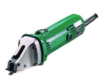
1.3 Panel Composition
     Trimoterm SNV fireproof panels consist of a completely galvanised shallow and deep-profiled colour coated steel
     sheet of 0.5 mm and 0.6 mm thicknesses. The steel sheet is bonded to the panel core which is made of incombustible
     lamellated class A1 mineral wool (EN 13501-1). All three layers make a solid panel with a thickness ranging
     between 60 - 200 mm depending on the required load-bearing capacity, tightness and assembly requirements.

     A protective polyethylene foil is applied to the panel surface to protect it during handling, transport and assembly.
     The foil is removed after the assembly has been completed.

     Panels can be up to 14 m long.

1.4 Technical Data
1.4.1 Basic Technical Data

             Table 1: Technical data for Trimoterm SNV roof panels

             Technical data SNV, SNV-3L                  SNV 60      SNV 80      SNV 100       SNV 120       SNV 150         SNV 172       SNV 200

             Panel thickness [mm]                            60          80         100              120           150           172           200

             Weight SNV [kg/m ] 2
                                     Fe 0.6 / Fe 0.6        18.9        21.3        23.7             26.1          29.7          32.4          35.7

             Min. roof slope                                                      5° or 3° with additional sealing

             Cover width [mm]                                                                    1000

             Panel length [m]                                                                   up to 14

             Complete Technical data are available in Technical Specification data sheet.

1.4.2 Coatings

     Trimoterm SNV roof panels consist of a filling (mineral wool) and covering made of galvanised pre-painted thin
     steel sheet. Steel sheet metal is preliminary hot galvanised (usually 275 g/m2) in compliance with EN 10346,
     and additionally protected by organic coating in accordance with the »coil-coating« process (DIN EN 10169/1).

     The following basic types of organic coating protection are applied to the steel sheet metal:
     - based on SP polyester
     - based on PVDF polyvinylidene fluoride
     - based on PUR polyurethane
     - based on PVC polyvinyl chloride, coating or film

     Individual types of organic protection with the basic characteristics are presented in Table 1.

     Table 2: Basic characteristics of an individual type of organic coating or protection.

      TYPE OF CORROSION PROTECTION                                       SP      PVDF         PVDF+         PUR       PVC(P)           PVC+F
      Corrosion classification [DIN 55928-8]                              III      III         III           III           III           III
      Total organic thickness (my) [EN 13523-1]                          25        25          35            50       175-200       120-200
      Temperture resistance (°C)                                         +80      +110        +110          +110          +70           +70
      UV resistance category [EN 13523-10]                              Ruv3      Ruv4         Ruv4         Ruv4          Ruv2           —
      Flexibility                                                        ••       •••         ••••          ••••          ••••          ••••
      Staining resistance                                                •••      ••••        ••••          ••••          ••            ••••

     Note:
     •••• suitable without reservations ••• very suitable •• suitable • suitable with reservations/contact Trimo -
     unsuitable
     Note: detailed coating explanation together with Instructions for the use and Maintenance can be found in »Technical instructions for
     the use and maintenance of Trimo products«.

2                                                                                         SNV Technical document | EN | Version 6 | April 2019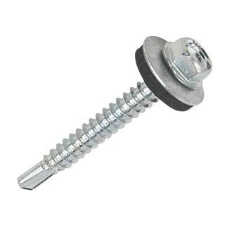
2      Design Procedure
2.1 Panel Thickness Selection
       With respect to the client’s or project’s requirements or in accordance with the legislation appropriate thickness
       of Trimoterm SNV roof panel shall be selected. Thickness has a direct influence on the load-bearing capacity of
       the panel, thermal insulation of the roof and heat stability of the structure.

2.2 Structural Design Data
       Allowed distances between supports are determined in relation to the selected panel thickness, loads and support
       widths.

       Exact Structural calculation is available by contacting Trimo Technical service.

2.3 Fixing Method
       Structural engineer will determine the required number of screws in accordance with the standards and regulations
       of an individual country. A detailed calculation prepared by Trimo’s technical department is recommended for each
       individual building. The principle of screw arrangement relating to the calculated number is shown in Fig. 1.

               Fig. 1: Fixing arrangement.

                                                                  1 screw per panel in each purlin

                                                                  2 screws per panel in each purlin

                                                                  3 screws per panel in each purlin

                                                                  4 screws per panel in each purlin

       The main factors influencing the fixing calculation are:

       Wind load:
       - basic wind load,
       - height of building above the ground,
       - area on the roof (edge and corner areas are more exposed to wind suction).

       Building type:
       - Open, partly open, closed buildings.

       Various loads appear on the roof in relation to the factors mentioned and the fixing method should be adjusted to
       accommodate them. Fig. 2 shows the characteristic fixing areas.

       Tables for the calculation of fixing are given in Separate document.

       Tables for the calculation of fixing are given in the Appendix to the catalogue.

               Fig. 2: Characteristic fixing areas.

SNV Technical document | EN | Version 6 | April 2019                                                                   3
2.4 Snow Guards
2.4.1 General
Installation of snow guards is recommended for all buildings where sliding of snow may present a danger
to people and property. Legislation in various countries prescribes obligatory installation of snow guards on
buildings with roofs where the inclination is greater than 22° (e.g. Slovenia), but the experience shows that they
are actually needed also on low pitch roofs.
For Trimoterm SNV roof panels snow guards of type 330 placed in a line are used. They are made of galvanised
and colour coated steel sheet.
2.4.2 Snow Guards Arrangement and Fixing
As a priority, snow guards arranged in a line are fixed with screws that are intended for fixing panels on purlins.
The fixing method and the basic principle of arrangement are presented in Fig. 3 and 4. Informative number of
snow guards required and the corresponding number of screws required for fixing per panel width are shown
in Table 3.
Table 3: Number of snow guards and number of screws.
Length of a roof slope
Snow 0-6 (6) - 10 (10) - 15 (15) - 20 (20) - 25 (25) - 30
So
( k N / Roof angle ß nv Ns nv Ns nv Ns nv Ns nv Ns nv Ns
m2)
0° - 10° 2 1 2 1 2 1 2 1 4 1 4 1
0,75 (10°) - 20° 2 1 3 1 4 2 4 3 4 3 4 3
(20°) - 30° 2 1 4 3 4 3 4 3 4 4 4 4
0° - 10° 2 1 2 1 2 1 4 1 4 2 4 3
1,00 (10°) - 20° 2 1 4 1 4 3 4 3 4 3 4 4
(20°) - 30° 4 1 4 3 4 4 4 4 4 4 4 5
0° - 10° 2 1 2 1 4 1 4 2 4 3 4 3
1,25 (10°) - 20° 3 1 4 2 4 3 4 3 4 4 4 4
(20°) - 30° 4 2 4 3 4 4 4 4 4 5 4 6
0° - 10° 2 1 2 1 4 2 4 3 4 3 4 3
1,50 (10°) - 20° 3 1 4 3 4 4 4 4 4 4 4 5
(20°) - 30° 4 2 4 3 4 4 4 5 4 6 4 7
0° - 10° 2 1 4 1 4 3 4 3 4 3 4 4
2,00 (10°) - 10° 4 2 4 3 4 4 4 5 4 5 4 6
(20°) - 30° 4 3 4 4 4 5 4 6 4 7 4 8
For roofs of inclination greater than 30° and higher loads a special calculation to determine snow guard number
and screw number is needed.
The first snow guard at the eaves should be fixed at the location of the first purlin.
4 SNV Technical document | EN | Version 6 | April 2019Fig. 3: Principle of snow guard arrangement on a roof slope.
Fig. 4: Number of screws per panel width.
Number of screws
SNV Technical document | EN | Version 6 | April 2019 53 Assembly Instructions
3.1 Installation Recommendations
Trimoterm SNV roof panels can be fixed into roof load-bearing steel, wood or concrete purlins with an intagrated
steel profile of minimal dimensions 60/40/3 (Fig. 5). For fixing into wood, lamelated beams are commonly used.
Where the substructure is made of solid wood, additional steel sheet is required.
Fig. 5: Sub-structure types for fixing Trimoterm SNV panels.
Minimal roof slope is α =3° (~5%). Maximum spans should be taken into account (Fig. 6).
Spans for Trimoterm SNV roof panels are determined in Trimo’s Technical department. The measures required
due to the inclination are presented in Section 3.2.1.
Fig. 6: Span and inclination of the roof slope.
Minimal intermediate support width is 60 mm.At the end support is 40 mm which is determined according to
static calculation (Fig. 7).
Fig. 7: Minimal support widths.
Intermediate support
End support
6 SNV Technical document | EN | Version 6 | April 2019Before the first panel is placed the substructure geometry should be checked.
The first panel is placed in the end crosswise axis of the building by suitable levelling in the eaves − rectangular
on the longitudinal axis of the building.
A dripping edge of at least 80 mm should be made on panels in the eaves to prevent moistening mineral wool
in the panel (Fig. 8). A dripping edge for longer panels is usually made by Trimo. Cleanliness of these edges has
to be checked on-site; if required the rests of wool and adhesive are to be removed. The dripping edge may be
on the left or on the right side (Fig. 9). In case of a saddle roof this enables simultaneous assembly on both roof
slopes from the same direction (Fig. 10).
Regardless of the roof inclination it is necessary to additionally bend the steel sheet of panels between trapezoids
in the eaves at an angle of 45° - 60° downwards (Fig. 11) using a suitable plumbing tool.
Fig. 8: Dripping edge of a panel.
Protection against moistening
Fig. 9: Left and right dripping edges.
Left dripping edge Right dripping edge
Fig. 10: An example of quick assembly of a saddle roof. Fig. 11: Bending of steel sheet in the eaves.
Trimoterm SNV panels have a protective foil applied on the top and bottom sides to protect its colour coated
surfaces against any possible damage during transport, handling and assembly. The foil is removed from the
bottom side before the assembly of an individual panel. From the top side it is removed before the work has
been completed. If necessary, it can be removed from some places already during the assembly (e.g. on the
longitudinal joint of two panels, under screws, flashing, etc. - Fig. 13). If panels are stored for a longer period of
time, the foil should be removed at the latest after the expiry of three months. If panels are stored in the open
air, they should be protected against the sun; otherwise removing of the foil may be difficult.
SNV Technical document | EN | Version 6 | April 2019 7Fig. 13: Removal of a protective foil.
When panels are cut during the assembly, only scissors and saws that do not heat the cutting edge to a high
temperature (Fig. 14) may be used. High temperature can destroy the anticorrosive protection in the immediate
vicinity of a cut. Therefore use of grinding machines is prohibited for such purposes! All small metal parts that
appear as a consequence of cutting and drilling have to be removed immediately from the surface of panels, or
at the latest when the daily work has been completed.
Fig. 14 Recommended tools for panel cutting.
Marking or scratching with nails or similar sharp objects that can damage the protective colour coated layer
is prohibited. Before panel assembly it should be checked that the end trapezoid that overlaps the trapezoid
of the neighbouring panel is completely clean (Fig. 15). If it is not, it must to be cleaned! Care should be taken
to ensure that the sealing tape already installed does not get damaged.
Fig. 15: Checking of trapezoidal panel section.
Mineral wool is protected by a self-adhesive tape which is placed on the longitudinal sides of the panel (Fig. 16).
The tape does not need to be removed before the assembly.
Fig. 16: Self-adhesive tape on longitudinal edges.
8 SNV Technical document | EN | Version 6 | April 20193.2 Sealing
3.2.1 Sealing the Longitudinal Joint Between Panels
During assembly special attention should be paid to ensure the tight fitting of panels. There should be no space
in the longitudinal joint between the neighbouring panels (Fig. 17).
Fig. 17: Tight fitting of panels.
If butyl or silicone mastic seal is to be placed into the longitudinal joint it should be applied in a way presented
in Fig. 18 and 19. Mastic seal is placed in an individual joint before the assembly of the following panel.
Fig. 18: Putting mastic seal in a panel.
Fig. 19: Detail of applying the mastic seal in a panel.
Installation position for other sealing materials is shown in Trimo Standard details.
SNV Technical document | EN | Version 6 | April 2019 93.2.2 Assurance of Roof Water-tightness
The limiting of roof slope and the measures required in case of such slope are presented in Table 4.
Table 4: Roof slope and measures required.
ROOF INCLINATION REQUIRED MEASURES
>5° 1. By default SNV panels are equipped with joint seals (Fig. 20).
(>8.8%) 2. Putting up of additional connecting screws is shown in Fig. 21. The num-
ber and arrangement are defined in the instructions for screwing and in
the assembly instructions.
3. Sealing of panel prolongation by means of pre-compressed expansion
sealing tape 20x2/10 mm in two lines is shown in Fig. 22. Exact perfor-
mance is shown in a detail of roof prolongation AA4/1 and in the assem-
bly instructions.
4. Bending of sheet metal on the low level between trapezoids, in the eaves
and in the ridge (Fig. 23).
5. Performance of openings by sheet metal over an opening is allowed up
to the ridge (Fig. 24) in compliance with details AB1/1 and AB2/1 or by
compatible Liquid waterproof coating.
Important Note:
TRIMOTERM SNV panels are watertight on draining water. Its design/en-
gineering responsibility to prevent “water pools” on the roof as a result of
insufficient slope and/or joint interface detail with regards to project condi-
tions. (rainfall, snow accumulation, roof shape and slope)
In addition to > 5 requirements we recommend:
3°-5°
(~5%-8.8%) 1. For inclines of 3-5°, it is necessary to create openings by compatible
Liquid waterproof coating.
2. Mineral wool core >114 kg/m3 is recommended
3. very tight structure tolerances to be assured. i.e. 3° ± 0,2°.
4. Max slope length 30m for locations with possible snow accumulation.
5. Max. slope length for all locations is determinate by ability of water to
drain from the roof not to create water pools to result water pressure
on the detailing.
Important Note:
TRIMOTERM SNV panels are watertight on draining water. Its design/en-
gineering responsibility to prevent “water pools” on the roof as a result of
insufficient slope and/or joint interface detail with regards to project condi-
tions. (rainfall, snow accumulation, roof shape and slope)
Fig. 20: Panel laying.
Sealing tape K 9/3
Sealing tape 7x7
10 SNV Technical document | EN | Version 6 | April 2019Fig. 21: Stitching screws on a longitudinal joint.
stitching screws
Fig. 22: Sealing of panel extension.
Fig. 23: Bending of steel sheet on the ridge and eaves.
Sealing a panel extension with pre-compressed sealing tape 20x2/10 mm arranged in two lines is shown in standard
detail AA4/1 and in the chapter 3.5 Installation details.
Fig. 24: Installation of an opening on a roof using a steel sheet
SNV Technical document | EN | Version 6 | April 2019 113.3 Panel Fixing
Only screws made of stainless steel and washers with a diameter of 19 mm (also of stainless steel) and EPDM
sealing tape may be used for fixing the panels. Minimal thickness of a screw is 6.3 mm for selftapping and 5.5
mm for selfdrilling fixings.
Panels are fixed through the trapezoidal sections by means of mandatory use of saddle washers with seals (Fig. 26).
Fig. 26: Fixing method of Trimoterm SNV roof panels.
Self-tapping screws of type A are used for fixing to wooden and thin steel purlins (steel thickness up to 3
mm). If steel purlins are 3 mm thick or greater, self-tapping screws of type B should be used. The use of self-
drilling screws of type C is also allowed for steel purlins. All screw types are presented in Fig. 27.
Fig. 27: Screw types
Type A Type B Type C
A borehole of a suitable diameter should be drilled through a panel and purlin according to instructions of the
fixing manufacturer if panels are fixed to a steel sub-structure with A or B type screws. Table 6 presents all
required sizes of boreholes of producer “SFS Stadler”. No preliminary drilling of holes is allowed for type C
fixings.
Table 6: Diameter of a borehole for a screw regarding thickness of a sub-structure.
Thickness of a sub-struc- Diameter of a borehole
ture [mm]
[mm]
2.0 - 3.0 (Type A) 5.00
3.0 - 3.9 5.05
4.0 - 4.9 5.35
5.0 - 5.9 5.65
6.0 - 10.0 5.80
>10.0 5.85
12 SNV Technical document | EN | Version 6 | April 2019Screw length depends on thickness of Trimoterm panels and sub-structure type in accordance with the
instructions of the fixing manufacturer. Care should be taken to tightening screws correctly to ensure they are
not too tight or too loose. Correct fixing method is presented in Fig. 28. The protective foil should be removed in
places before fixing (Fig. 29). The foil is finally removed after the works on the roof have been completed.
Fig. 28: Correct fixing of screws.
Fig. 29: Removal of the foil on a fixing place.
SNV Technical document | EN | Version 6 | April 2019 134 Installation Details
4.1 Roof Extension Detail
For long roof slopes (the maximum length of a panel is 14 m) longitudinal extension of panels is required. Therefore
a longitudinal extension detail is shown in Fig. 33. Fig. 34 presents a system of panel extension on a large roof
surface.
Fig. 33: Roof extension detail.
1 Sealing tape 20x2/10 5 Sealing tape K
2 Sealing tape 2x47 6 Joint seal
3 Self-tapping screw 7 Self-tapping screws 6.5x25
4 Saddle washer
Assembly sequence:
- Before assembling an individual panel a seal has to be inserted on a double or expanded single purlin (purlin
width min. 100 mm) (Item 2).
- A pre-compressed 20x2/10 mm expansion sealing tape is to be applied to a panel in two lines (Fig. 35), on an
overlap in a length of 200 mm.
- The overlapping part should be cleaned thoroughly before the assembly.
- Mineral wool of the top panel has to fit tightly to the bottom panel in the joint.
- Structural engineer calculates the number and arrangement of self-tapping screws (Item 3) over the purlin or a
panel is fixed at least into each second rib.
Fig. 34, 35: Correct and incorrect panel assembly sequence; panel assembly panels in the overlap.
PE seal Pre-compressed
2x47 mm expansion seal
20x2/10 mm
14 SNV Technical document | EN | Version 6 | April 20194.2 Ridge Detail
Fig. 36: Ridge detail on a saddle roof.
1 External ridge flashing 7 Butyl sealing tape 2x6 mm
2 Internal ridge flashing 8 Self-tapping screw 6.5x25
3 Covering flashing 9 Blind rivet 4x10
4 Thermal insulation 10 Saddle washer
5 Profile filler SNV - negative 11 Self -tapping screw
6 Sealing tape 3x15 mm
Assembly sequence:
- An internal ridge flashing (Item 2) is placed on the ridge purlin; a sealing tape (Item 6) is previously applied to the
purlin.
- Gradually Trimoterm SNV panels are placed on the left and the right side and they are fixed into the purlins.
- On the panel edge the top steel sheet is bent in a length of 30 mm by a suitable plumbing tool.
- SNV profile filler negative (Item 5) is placed on the panels.
- Panel masks (Item 3) are placed on it and then butyl tape (Item 7) is also applied.
- Empty space under a ridge tile is filled with low-density mineral wool (Item 4).
- At the end external ridge flashing (Item 1) is placed and is longitudinally prolonged by a plumbing joint or an overlap
in a min. length of 200 mm and sealed by neutral silicone putty in at least three lines.
- The external ridge flashing is fixed to each second rib of the panel with screws φ 6.3 x 25 mm.
SNV Technical document | EN | Version 6 | April 2019 154.3 External Gutter Detail
Fig. 37: External gutter detail.
1 External gutter hook 7 Internal eaves mask 13 Self - tapping screw 6.3x25
2 External gutter 8 Thermal insulation 14 Self - tapping screw
3 Outlet connection 9 Self -tapping screw 15 External eaves mask
4 Down pipe 10 Sealing tape 5x10 mm 16 Self - tapping screw 6.5x25
5 Down pipe support 11 Saddle washer
6 External gutter mask 12 Blind rivet
Assembly sequence:
- Trimoterm SNV panels are laid from the direction determined by the dripping edge of a panel. In case snow
guards
are installed on the roof, they are fixed to the final purlin (Item 14). The seal EPDM φ 28/3x3 has to be additionally
applied between a snow guard and a panel.
- Additional bending of steel sheet at an angle of 45° in a length of 10 - 15 mm (Fig. 12) is required in the eaves.
- An external eaves mask (Item 15) is riveted from the external side to the façade. Under the top, external gutter
hooks are pressed in the core of a Trimoterm SNV panel by using saddle washers (Item 11). Then they are fixed to
the top steel sheet with two screws. When arranging hooks special attention is to be paid to their length since they
ensure gutter inclination.
- External gutter (Item 2) is placed on these hooks and fixed by suitable bending of fixing steel sheet on the
hooks.
- Low density mineral wool (Item 8) is inserted into the closing space between the façade and Trimoterm SNV roof
panel from the inner side.
- Internal eaves mask (Item 7) onto which a sealing tape 3x15 mm (Item 10) is preliminarily applied is riveted from the
inside to the panels.
16 SNV Technical document | EN | Version 6 | April 20194.4 Valley Gutter Detail
Fig. 38: Valley Gutter Detail.
1 Self - tapping screw 7 Drip flashing 13 PVC foil 1,8 mm
2 Self - tapping screw 6,5x25 8 Self -tapping screw 6.5x25 14 PVC outlet connection
3 Sealing tape 5x10 mm 9 Blind rivet 15 Geotextiles
4 Gutter mask 10 Trimoterm FTV 16 PVC outlet connection
5 Covering flashing - positive 11 Self – drilling screw 17 PVC foil 1,8 mm (homogenous)
6 Thermal insulation 12 Flashing
Assembly sequence:
- Initially both gutter masks (Item 4) are placed on the load-bearing purlins and temporary fixed. A sealing tape
5x10 mm (Item 3) is applied onto both gutter masks.
- Trimoterm SNV panels are laid regarding orientation of the dripping edge of a panel. Panel steel sheet has to be
bent at an angle of 45° in the eaves between trapezoids (Fig. 11).
- Through saddle washers Trimoterm SNV panels and gutter masks are fixed to load-bearing purlins by screws.
- Longitudinally cut Trimoterm FTV panel is laid on the gutter masks (Item 4) and fixed with self-tapping screws
(Item 2).
- Soft thermal insulation (Item 6) is installed.
- Drip flashings (Item 7) and flashings (Item 12) made of steel sheet laminated with PVC (0,8 mm) are fixed with blind
rivets and self-tapping screws.
- On the prolongation joints of drip flashings (Item 7) and flashings (item 12) homogenous PVC membrane is welded
(item 12) to make the joints waterproof.
- PVC membrane (Item 13) is welded to drip flashings (Item 7) and flashings (Item 12).
- Finally covering flashing – positive is fixed.
Fig. 39: Profile filler SNV – positive
SNV Technical document | EN | Version 6 | April 2019 17TRIMO D.O.O.
PRIJATELJEVA CESTA 12,
8210 TREBNJE, SLOVENIA
T: +386 (0)7 34 60 137
F: +386 (0)7 34 60 127
Published by: Trimo d.o.o., EN / 04/2019
TRIMO@TRIMO-GROUP.COM
WWW.TRIMO-GROUP.COM
Trimo Group holds full copyrights on the information and details provided on this media, therefore any unauthorized reproduction and distribution is strictly prohibited. Professional care has been taken to ensure that information/details
are accurate, correct and completed and not misleading, however Trimo, including its subsidiaries, does not accept responsibility or liability for errors or information, which is found to be misleading. Information/details on this media
are for general purposes only. Use of it is on your own initiative and responsibility for compliance with local laws. Any deviations in details and project solutions are user responsibility. In no event, will we be liable for any loss or damage
including without limitation, indirect or consequential loss or damage, or any loss or damage whatsoever arising from loss profits arising out of or in connection with, the use of this media. All information issued by Trimo Group is
subject to continuous development and information/details contained on this media are current at date of issue. It is user`s responsibility to obtain most up-to-date information from Trimo when information/details are used for project.
The last version of the document is available on www.trimo-group.com. Latest version of published document in English language prevails over other translated language documents.
For information about the delivery of panels see Trimo’s General conditions (https://trimo-group.com/en/trimo/general-conditions-of-sale).You can also read