Electrathon Vehicle: Front Suspension - ScholarWorks@CWU
←
→
Page content transcription
If your browser does not render page correctly, please read the page content below
Central Washington University
ScholarWorks@CWU
All Undergraduate Projects                                                                              Undergraduate Student Projects

Winter 2020

Electrathon Vehicle: Front Suspension
Christopher Clark
clarkch@cwu.edu

Follow this and additional works at: https://digitalcommons.cwu.edu/undergradproj
     Part of the Automotive Engineering Commons, and the Mechanical Engineering Commons

Recommended Citation
Clark, Christopher, "Electrathon Vehicle: Front Suspension" (2020). All Undergraduate Projects. 101.
https://digitalcommons.cwu.edu/undergradproj/101

This Undergraduate Project is brought to you for free and open access by the Undergraduate Student Projects at ScholarWorks@CWU. It has been
accepted for inclusion in All Undergraduate Projects by an authorized administrator of ScholarWorks@CWU. For more information, please contact
scholarworks@cwu.edu.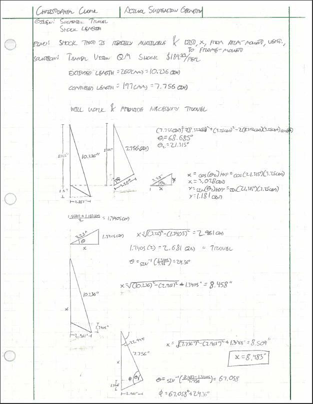
ELECTRATHON VEHICLE: FRONT
       SUSPENSION
               By
        Christopher Clark

         Team Members:

        Lathan Halaapiapi
         Luis Hernandez
          Ryan Shiner
          Sam Johnson
Table of Contents
1. Introduction
   1.1. Description
   1.2. Motivation
   1.3. Function Statement
   1.4. Requirements
   1.5. Success
   1.6. Scope
   1.7. Benchmark
   1.8. Success of Project
2. Design & Analysis
   2.1. Approach
   2.2. Design Description
   2.3. Benchmark
   2.4. Performance Predictions
   2.5. Description of Analysis
   2.6. Scope of Testing and Evaluation
   2.7. Analysis
       2.7.1. Design Issue
       2.7.2. Calculated Parameters
       2.7.3. Best Practices
   2.8. Device: Parts, Shapes, and Conformation
   2.9. Device Assembly, Attachments
   2.10.       Tolerances, Kinematics, Ergonomics, etc.
   2.11.       Technical Risk Analysis, Failure Mode Analysis, Safety Factors, Operation
        Limits
3. Methods and Construction
   3.1. Construction
       3.1.1. Description
       3.1.2. Drawing Tree, Drawing ID’s
       3.1.3. Parts List and Labels
       3.1.4. Manufacturing Issues
       3.1.5. Discussion of Assembly, sub-assemblies, parts, drawings
4. Testing Method
   4.1. Introduction
   4.2. Method/Approach
   4.3. Test Procedure Description
   4.4. Deliverables
5. Budget, Schedule, & Project Management
   5.1. Proposed Budget
       5.1.1. Discuss Part Suppliers, substantive costs and sequence or buying issues
       5.1.2. Determine labor or outsourcing rates & estimate costs
       5.1.3. Labor
       5.1.4. Estimate total project cost
       5.1.5. Funding Sources
   5.2. Proposed Schedule

                                                                                           2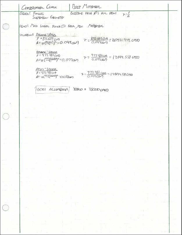
5.2.1. High-level Gantt Chart
       5.2.2. Define Specific Tasks. Identify them, and assign times
       5.2.3. Allocate task dates, sequence and estimate duration
       5.2.4. Specify deliverables, milestones
       5.2.5. Gantt Chart
   5.3. Project Management
       5.3.1. Human Resources
       5.3.2. Physical Resources
       5.3.3. Soft Resources
       5.3.4. Financial Resources
6. Discussion
   6.1. Design Evolution / Performance Creep
   6.2. Project Risk Analysis
   6.3. Successful
   6.4. Project Documentation
   6.5. Next Phase
7. Conclusion
   7.1. Restate your design title and its complete design readiness.
   7.2. Restate your important analyses and how this contributes to success.
   7.3. Restate your design predicted performance vs actual performance, with respect to your
        requirements. Use bullets if appropriate.
8. Acknowledgements
9. References
Appendix
   Appendix A – Analysis
       A-1: Frame Length & Track
       A-2: Reaction @ Each Front Wheel
       A-3: Base Suspension Geometry
       A-4: Actual Suspension Geometry
       A-5: Spring Rate
       A-6: New A-Arm Length
       A-7: Suspension Loading
       A-8: Shock Loading
       A-9: Max A-Arm Loading
       A-10: Bolt Material
       A-11: Shock Bracket Materials
       A-12: A-Arm Material
   Appendix B – Drawings
       B-1: Bracket
       B-2: Bracket Bolt
       B-3: Bracket Nut
       B-4: Lower A-Arm
       B-5: Shock Bracket Bot
       B-6: Shock Bracket Nut Bot
       B-7: Shock Bracket Bolt Bot
       B-8: Shock Bracket Top

                                                                                                3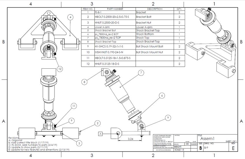
B-9: Assembly
Appendix C – Parts List
Appendix D – Budget
Appendix E – Schedule
Appendix F – Expertise and Resources
Appendix G – Testing Data
Appendix H – Evaluation Sheet
Appendix I – Testing Report
Appendix J – Job Hazzard Analysis
Appendix K – Resume

                                       4
Abstract
        Central Washington University does not currently have a competition field-able
Electrathon America electric vehicle with adequate front suspension. The aim of this project was
to provide the vehicle with handling that supports sound ground contact throughout the
competition environment. Handling that supports sound ground contact is important for vehicles
so they can go around corners without a loss of traction or flipping over. The solution to this
engineering problem was designed and tested through various requirements. The requirements at
hand were that the suspension components weigh less than 20 pounds, that there be no more than
3 inches of suspension travel, and that the working device must support the overall vehicle
weight of 350 pounds. The working device was created through analysis based around these
three requirements. For consideration of weight, the a-arm and bottom shock mounts were milled
out of billet aluminum, and the top shock mounts were made from angle steel and welded to the
frame. The success of the project was dependent on the final performance of the working device.
This success was based on the results of testing the working device. Testing showed that the
working device weighed 20 pounds, the vehicle had 2.5 inches of suspension travel, and the
working device supported the full weight of the vehicle.

                                                                                               5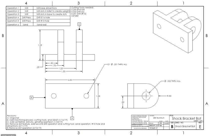
1. INTRODUCTION

  1.1. Description:
       The problem to be addressed is that Central Washington University does not currently
       have a field-able Electrathon America electric vehicle with adequate front suspension.
       The aim is to provide the vehicle with handling that supports sound ground contact
       throughout the competition.

  1.2. Motivation:
       This project was motivated by a need for devices that provide ground contact and
       stability of an Electrathon America electric vehicle. Two separate cars exist, but neither
       of them are in good running condition. The first one is a cycle-car configuration with a
       carbon fiber body. This car has a battery housing, electric motor, seat, some steering
       components, and suspension. The second one is a tricycle configuration. This car is
       complete, but not in fielding condition.

  1.3. Function Statement:
       To design, build, and field a car for the 2018/2019 Electrathon America electric vehicle
       design competition, specifically suspension. The suspension will provide the vehicle
       with complete stability and ground contact throughout the competition.

  1.4. Requirements:
       The design and racing requirements are stated in the Electrathon America Handbook
       2018/2019. The completed vehicle will adhere to these rules and regulation, as well as
       participate in a race. In addition to these are the following requirements:
       • Suspension components weigh less than 20 lbs.
       • Maximum 3” of suspension travel
       • Must support the overall vehicle weight of 350 lbs.

  1.5. Success Criteria:
       Success will consist of fielding the vehicle in an Electrathon America event, and not
       having any part of the suspension fail to maintain adequate ground contact. Additionally,
       the handling characteristics of the vehicle will positively impact the driving.

  1.6. Scope of this effort:
       Will only include the front suspension of the Electrathon America vehicle and all of the
       accompanying analyses for dimension and materials. Additionally, the suspension will
       be tested when built.

  1.7. Benchmark:
       The benchmark for this project is the existing, complete vehicle. The aim is to create a
       vehicle that is better than this one.

  1.8. Success of the Project:
       Success depends on the final performance of the suspension components in a
       competition setting and meeting the requirements.

                                                                                                    6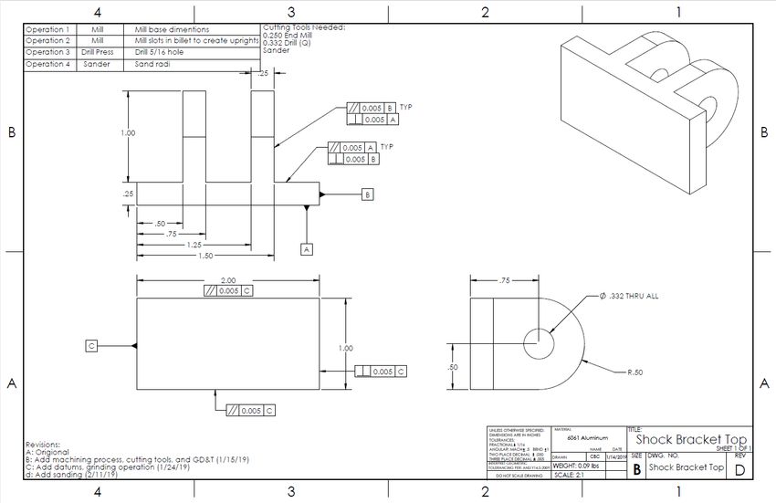
2. DESIGN & ANALYSIS

  2.1. Approach:
       The proposed solution is to design a McPherson-based front suspension. Using a
       McPherson strut-based design will be the simplest way to design the new suspension.
       This design incorporates a lower control arm and a shock with spring. The control arm
       will attach the wheels to the frame. The shock will extend between the arm and the
       frame and will transfer weight and provide stability in corners. This design will need to
       be further modified before field-ability of the vehicle. This is an example of the basic
       suspension configuration that this solution will be based off of.

  2.2. Design Description:
       The control arm will be connected to the frame through two mounts and to
       corresponding bolts. The shock will be connected to the frame by a mount and a bolt.
       The mounts will be welded to the frame. The control arm is of an a-arm design. The
       shock will be connected to the control arm by a mount and a bolt. The shock that will be
       used is the Tanner Vision QM Shock. This shock is a coil over design. The
       accompanying spring will provide the necessary rebound for the vehicle to maintain
       stability. This is the first sketch of the design. This design will likely be modified
       throughout the design process.

                                                                                                   7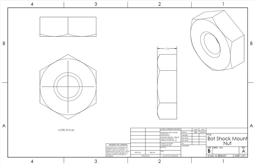
2.3. Benchmark:
The benchmark for this project is the existing, complete vehicle. The aim is to create a
vehicle that is better than this one. The most important requirement is to provide stability
of the 350 lbs vehicle.
2.4. Performance Predictions:
The suspension components will weigh less than 4.5 lbs on each side. The suspension
will not fail when cornering, where a maximum force of 1025 lbs is put on the
suspension.
2.5. Description of Analysis:
The first thing to do was to determine the dimensions of the frame in order to find the
wheel track (Appendix A-1). Finding the wheel track was done first so that an
approximate a-arm length could be determined. The requirement that the suspension can
support the 350 lbs vehicle required the need to find the static load on each front wheel.
This was done using force equilibrium equations (Appendix A-2).
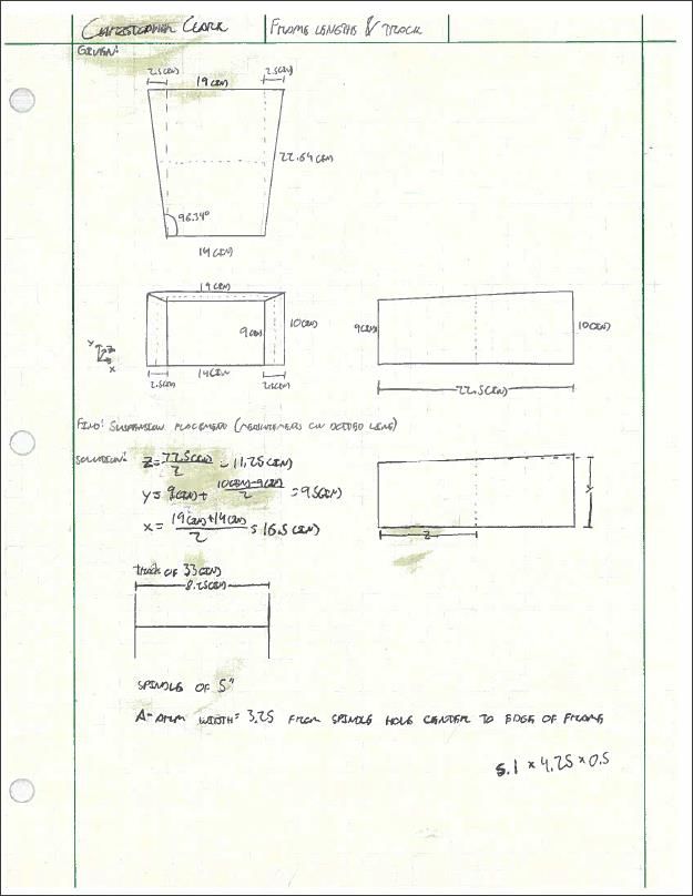
Once this load was found, the geometry and dimensions of the suspension were found.
Preliminary shock length and suspension travel values were calculated, based off of the
frame dimensions (Appendix A-3). Based on these preliminary numbers, a shock was
selected that was close to the length and travel needed. The a-arm length and the
mounting point for the top shock mount were calculated based on the shock selection
(Appendix A-4). Along with the shock selection, an accompanying spring was selected.
Because of the specific shock, a spring rate had to be calculated. Using the static load at
8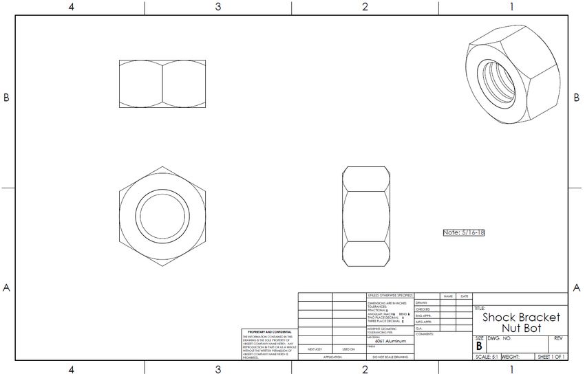
each wheel and the dimensions of the a-arm, an appropriate spring rate was found
    (Appendix A-5). The closest spring rate was selected, and a new a-arm length was
    calculated based off of this new spring rate (Appendix A-6). This calculation was done
    so that the higher spring rate would not negatively affect the functionality of the vehicle.

    Once the length of the a-arm and the location of the shock mounting points were
    determined, the suspension loading was found. Through the use of force equilibrium
    equations, the forces acting on the a-arm and the shock, when under the previously
    found static loads, were found (Appendix A-7 & A-8). Additionally, a maximum loading
    was calculated for the a-arm (Appendix A-9). This maximum loading was based on the
    possibility of the entire weight of the 350 lbs vehicle being put laterally on the arm while
    in a hard corner. The maximum loading calculations yielded the maximum forces that
    the pins would experience.

    The last analysis to do was to use the maximum forces towards the selection of materials
    for the bolts, brackets, and the a-arm. The material selection for the bolts was determined
    by calculating the shear at each pin (Appendix A-10). The material selection for the
    shock mounting brackets was found using shear at the point with the smallest cross-
    sectional area (Appendix A-11). For the purposes of easier welding, the shock mounts
    are the same as the material the they will be welded to. The material selection for the a-
    arm was determined by finding the shear at the two locations with the highest loadings
    (Appendix A-12). These locations were also the point of the smallest cross-sectional
    areas on the arm.

    Additional analysis was done on the a-arms to drill holes to bolt the bottom shock mount
    instead of welding it (Appendix A-13). This was done to cut down on manufacturing and
    construction time as the original slot on the bottom face of the bottom shock mount was
    no longer required. It was determined that the new bolt holes will not hinder the integrity
    of the lower a-arm to function as desired.

2.6. Scope of testing and Evaluation:
     To test the design of the front suspension, it will be constructed and installed on the
     vehicle. The vehicle will be fully loaded, and the suspension will be inspected for
     buckling and fatigue. The travel of the suspension will be tested by measuring the ride
     height of the vehicle when under loadings.

2.7. Analyses

   2.7.1. Design Issue:
          The design issue at hand was to create new front suspension for the vehicle. The
          requirements of the suspension handling the 350 lbs vehicle weight and weighing
          less than 4.5 lbs per side led to the analyses. The outcomes of the analyses were
          the a-arm, shock and spring selection, shock mounting brackets. Additionally, all
          of the materials for the manufactured parts and the appropriate mounting
          hardware.

                                                                                               9
2.7.2. Calculated Parameters:
The parameters were calculated using the methods discussed in section 2.5
Description of Analysis. It was determined that the a-arm, bottom shock mount,
and bolts will be made out of 6061 aluminum (Appendix A-10, A-11, A-12). This
material is a good selection because it is strong enough for the application,
lightweight, low cost, and readily available. The arm will be bolted to the frame
with 1/4”-20 X 2.5” X 3/4” bolts and 1/4”-20 nuts. The shock will be bolted to the
shock mounts with 5/16”-18 X 1.5” X 7/8” bolts and 5/16”-18 nuts. The bottom
shock mount will be welded to the a-arm. The location of the mounting is fixed
and cannot be moved due to the design of the mount to slot around the a-arm.
Upon beginning manufacturing of the suspension components, it was determined
to bolt the bottom shock mount to the lower a-arm, instead of welding it.
2.7.3. Best Practices:
As found in the Mott book, a safety factor of 2.5 was selected to use throughout
the project. This was selected based on the provided safety factors commonly
used in industry.
2.8. Device: Parts, Shapes, and Conformation
2.9. Device Assembly, Attachments:
Assembly of the front suspension will consist of attaching the control arm to the vehicle
and the attaching the shock to connect the control arm to the vehicle. The final assembly
arrangement is in Appendix B-9. Once assembled, the steering spindle can be bolted to
the control arm.
2.10. Tolerances, Kinematics, Ergonomics
2.11. Technical Rick Analysis, Failure Mode Analysis, Failure Mode Analyses, Safety
Factors, Operation Limits
3. METHODS & CONSTRUCTION
3.1. Construction
3.1.1. Description:
The front suspension will be built in sections. The left and right sides are mirrors
of each other. The sections needed for assembly are the Lower A-arm arm, shock
mounting brackets, and fasteners. The control arm and the shock mounting
brackets will be manufactured. The shocks, springs and fasteners will be
purchased from suppliers. The control arm will be manufactured first, followed by
the brackets. First, the mounting brackets will be welded to the frame. Second, the
control arm will be mounted to the frame via the mounting brackets. Third, the
shock and spring will be assembled, per manufacturer instructions, and mounted
10to both the frame and the lower a-arm arm. In all three steps, fasteners are used to
hold the sections together.
After manufacturing the shock mounts, it was determined that the bottom shock
mount will be bolted to the lower a-arm. And the upper shock mount
3.1.2. Drawing Tree, Drawing ID’s:
The drawings for the parts and the assembly drawing is located in Appendix B.
Assembly
Bolt Together
Assemble Round Bracket
Bolt Together Weld to Frame
Shock Mounts
Shock Mount Shock Mount
Spring
Bot Top
A-Arm Shock
The shock mounts were made first. The top shock mounts had to be
remanufactured due to the fact that welding aluminum to steel is very difficult and
requires special materials.
Upon further inspection of the frame, the upper shock mounts are welded to the
frame, and the lower shock mount bolted to the a-arm.
3.1.3. Parts list and labels:
The parts list is Appendix C. This parts list is identical to the Bill of Materials on
Drawing B-9.
3.1.4. Manufacturing Issues:
After the design process and material selection, it was found that the section of
the frame that the upper shock mount will be welded to was made from aluminum
not steel, as previously thought. Because of this, the upper, along with the lower,
shock mount bracket will be made from 6061 Aluminum.
11During the construction of the parts, potential issues could be that drill bits are too
worn down to abide by the tolerances set forth. Milling the a-arm and shock
mounts could be required to be done by hand, and not through a CNC machine.
During the construction of the shock mounts it was found that using a band saw to
rough cut the material on the outsides of uprights was more time efficient than
using a mill to do the same operation. The slot was milled with a ½ inch end mill,
instead of a ¼ inch end mill. This was done because the ½ end mill was already
mounted in the milling machine. Additionally, less passes were required to make
the slot.
After both the bottom and top shock mounts were made, the fit to the shock was
tested. There were no problems regarding the bottom shock mounts. As for the
top shock mounts, the shock body around the bottom mounting hole hit the
bottom of the slot. The solution was to mill the center of the slot deeper to add
clearance for the shock to rotate around the hole. This solution worked.
Once the components were being fitted, there was interference between the a-arm
and the frame brackets. The solution was to use an angle grinder and a cutoff
wheel to remove material from the brackets until there was no interference.
After construction of the top shock mounts, it was found that the frame uprights
that these mounts were to be welded to were stainless steel, not aluminum as
previously informed of. Therefore, the aluminum top shock mounts would not
work. One avenue was to look in to if the mounts could be secured by a means
other than welding. The solution was to use small flat-bar that was folded around
the mount and then bolt the mount to the flat-bar, and the flat-bar to the frame
upright. This proved unreliable. The final solution was to use angle steel to mate
new mounts, ones that could be welded to the existing frame upright. These final
mounts were made from angle steel.
3.1.5. Discussion of assembly, sub-assemblies, parts, drawings (examples):
The assembly is Drawing B-9. There are no sub-assemblies. The parts for the
project are Drawings B-1 through B-8. On Drawing B-9, there is a Bill of
Materials that itemizes the needed parts for the assembly. The entire front
suspension is comprised of a left assembly and a right assembly.
4. TESTING METHOD
4.1. Introduction:
The weight of the suspension components will be measured by removing those
components from the Electric Vehicle and weighing them on a scale, the weight will be
recorded for the purpose of showing that the requirement to have the suspension
components weigh less than 20 pounds. The suspension travel of less than 3 inches will
be tested by measuring the distance from the bottom of the frame to the bottom of the
12tire when unloaded and then again when under load. The suspension travel will be
measured and recorded to show that the requirement has been fulfilled. The ability of the
suspension to support the overall vehicle weight of 350 pounds will be tested by
mounting the front suspension on the vehicle and simply seeing if it fails or not.
4.2. Method/Approach:
To measure the weight, a scale will be used. To measure the suspension travel, a caliper
will be used. To measure the ability of the suspension to support the full 350 pound
weight of the vehicle, the suspension will simply be put on to the vehicle. No test jigs
will be created because the Electric Vehicle will be sufficient to test the front
suspension.
4.3. Test Procedure:
The testing procedure for the requirement of less than 3 inches of suspension travel will
be tested by mounting the front suspension on the frame and measuring the travel of the
bottom of the frame to the bottom of the tire when under load. The testing procedure for
the requirement that the suspension components weigh no more than 20 pounds will be
tested by weighing the completed components of the suspension and calculating the
overall weight. The testing procedure for the requirement that the suspension will
support the overall weight of the vehicle will be tested by simply mounting the
suspension to the frame of the completed vehicle.
4.4. Deliverables:
Testing of the suspension will yield that it fulfills the requirements. The deliverables will
show that the total components do not weigh more than 20 pounds, as shown on a scale.
Additionally the suspension will be able to support the 350 pound vehicle.
The first test conducted was the travel of the front suspension. This test showed that the
design of the front suspension was sufficient to fulfill the requirement in which it was
designed for. The requirement that there was no more than 3 inches of travel. The results
of this test are in Appendix G of the project report. There were no issues with any of the
bought or constructed components or their integration of this project. Because of this, no
modifications need to be made to the design or the existing components. There were no
issues that were brought forth by this test.
The second test conducted was the weight of the front suspension components,
excluding the top shock mounts as they are welded to the frame and cannot be removed.
This test showed that the design of the front suspension was light enough to meet the
requirement that it was designed for. The requirement that the components weigh less
than 20 pounds. The results of this test are in Appendix G of the project report. There
were no issues with any of the bought or constructed components or their integration of
this project. Because of this, no modifications need to be made to the design or the
existing components. There were no issues that were brought forth by this test.
5. BUDGET/SCHEDULE/PROJECT MANAGEMENT
135.1. Proposed Budget
5.1.1. Part Suppliers, substantive costs and sequence or buying issues:
The shocks and springs will be purchased or supplied by Kaz Technolgies. The
raw materials will be purchased from McMaster-Carr. The nuts and bolts will be
purchased from a hardware store as low quantities are needed so buying in bulk
does not make sense. After redesigning the parts, it was determined that the
material for the a-arm and the shock mounts will be sourced from CWU. Because
CWU provided the materials, the cost was zero.
5.1.2. Determine labor or outstanding rates & estimate costs:
Due to CWU personnel assisting with the manufacturing and construction, there
were no labor costs. There are, however, outstanding rates as none of the budget
line items have been reimbursed. The budget sheet, Appendix D, contains an
estimated breakdown of costs for the project.
5.1.3. Labor:
For the front suspension, labor costs associated will be because of assistance with
machining the a-arm and/or welding the shock mount brackets. In manufacturing
the different parts, no labor costs had accrued.
5.1.4. Estimate total project costs
From Appendix D,
5.1.5. Funding sources:
Sources of funding could include using funds from the existing SME and ASME
clubs. Additionally, an EV club could be created to gain funding from ASCWU
that is given to clubs and organizations. Manufactures could also sponsor the team
with funds and/or parts. The machine shop could also provide raw materials such
as the 6061 aluminum. The rest of the costs not funded will come out of pocket.
5.2. Proposed Schedule
5.2.1. High-level Gantt Chart:
The Gantt chart is in Appendix E.
5.2.2. Define specific tasks and assign times:
5.2.3. Allocate task dates, sequence and estimate duration:
5.2.4. Specify deliverables:
The deliverable for the proposal section is the completed proposal. The
deliverables for the analyses section are the green sheets with the completed
analyses. The deliverables by 11 January 2018 are, a specified, five manufactured
parts. The a-arm, shock mounting brackets, and bracket bolts are going to be
machined. The specified deliverables were completed as of 7 March 2019. The
14delay in manufacturing was due to the 3-week delay in receiving funding from
ASCWU.
5.2.5. Estimate total project time:
Outlined in Appendix E, the estimated total project time is based on the back
calculation of time required for the first 6 weeks of the project.
5.2.6. Gantt Chart:
The Gantt chart is located in Appendix E.
5.3. Project Management
5.3.1. Human Resources:
The most important human resources are the members of the EV team, mentors,
staff, and faculty.
5.3.2. Physical resources:
The project will require the use of machines to manufacture the parts. The drill
press, milling machine, and CNC machine will be used. A welder will be used to
weld the shock mounts. The machines and welder will be used at Central
Washington University.
5.3.3. Soft Resources:
In addition to the physical resources, other resources will also be used. The CAD
labs in Hogue and the EV room will be paramount towards the success of this
project.
5.3.4. Financial Resources:
Financial Resources will include personal funding, grants, sponsorships, and club
funding from CWU.
6. DISCUSSION
6.1. Design Evolution:
The design of the front suspension has evolved throughout the process. The original
sketch of the design was a simple McPherson strut design with an a-arm-design control
arm. The design evolved to lengthen the arm in order to accommodate a longer shock.
This change led to the need for a stronger material in the arm and the pins. The design
has seven major components: the brackets that attach the a-arm to the frame, the bolts
that hold the a-arm to the frame, the a-arm, the mount that attaches the bottom of the
shock to the a-arm, the bolt that connects the bottom of the shock to the a-arm mount,
the mount that attaches the top of the shock to the frame, and the bolt that connects the
top of the shock to the frame mount.
The brackets that attach the a-arm to the frame were originally going to be
manufactured, but it was determined that the existing brackets will be sufficient for the
15design. The brackets will be slightly modified, to include a R0.75” fillet, in order reduce
weight (Appendix B-1). The a-arm design was changed, because of the appropriate
spring rate, to be longer than originally planned (Appendix A-6 & B-4). The bottom
shock mount was modified to include slots on the bottom to fit around the components
of the a-arm (Appendix B-5). This slot-in can be observed in the whole assembly
drawing (Appendix B-9). Both the bottom and top shock mount brackets were modified
to include a half inch fillet in order to save weight and provide clearance for the shock
(Appendix B-5, B-8). The inclusion of the fillets in the design and modifications of the
brackets was done in a way as to keep the cross-section area of the bracket constant
throughout the radius of the end of the bracket (Appendix B-5, B-9). One issue was than
after the initial design process, it was found that the frame uprights, that the upper shock
mount bracket will be welded to, were aluminum. Not steel as previously informed of.
Due to this, both the lower and upper shock mounts will be made from 6061 Aluminum.
This will further decrease the overall weight of the front suspension and make welding
the components to the frame an easier process.
For ease of manufacturing and construction bolt holes were drilled in the a-arm and the
bottom shock mount so that they can be bolted together instead of welded. These holes
will not hinder the functionality of the a-arm or weaken the material to an unwanted
point (Appendix A-13).
After the top shock mounts were manufactured, it was found that there was interference
between the bottom of the slot and the material of the shock. To get rid of this
interference, an end mill was used to mill a slight slot in the bottom of the existing slot.
During construction the steering spindles were mounted so that the a-arms will be angled
downwards. This was done to accommodate for the new coilovers, which were longer
than the original shocks.
Upon further, and incorrect, information, the frame uprights were stainless steel, not
aluminum or steel. Because of this the upper shock mounts were remade using angle
steel. The holes were located 0.500 inch from the top surface of the material to keep the
same placement as the original design. These were welded to the frame uprights 5.5
inches down from the bottom of the top tube of the frame on each side. The vertical
placement of these is not crucial as the selected coilovers have a degree of height
adjustability.
The original a-arm bolts were used instead of the new ones because the box containing a
majority of the new fasteners was taken.
The first test conducted was the travel of the front suspension. This test showed that the
design of the front suspension was sufficient to fulfill the requirement in which it was
designed for. The requirement that there was no more than 3 inches of travel. The results
of this test are in Appendix I of the project report. There were no issues with any of the
bought or constructed components or their integration of this project. Because of this, no
16modifications need to be made to the design or the existing components. There were no
issues that were brought forth by this test.
The second test conducted was the weight of the components. This test showed the
design met the requirement to not exceed 20 pounds. The results of this test are in
Appendix I. There were no issues with any of the bought or constructed components or
their integration of this project. Because of this, no modifications need to be made to the
design or the existing components. There were no issues that were brought forth by this
test.
6.2. Project Risk Analysis:
The project risk analysis was conducted on mounting the shock and spring.
6.3. Successful:
Based on the preceding discussion, one can conclude that the finished product meets the
success of the project, from Section 1.8
6.4. Project Documentation:
This project is documented in this report, the analyses done (Appendix A), the drawings
completed (Appendix B), and the schedule (Appendix E).
6.5. Next Phase:
The next step is to make the vehicle compliant and meet the requirements of the
Electrathon America Handbook so that the car can take place in a race.
7. CONCLUSION
7.1. Title and Design Readiness:
The Electrathon America Electric Vehicle: Front Suspension will be manufactured and
completed along with the other of the components of the vehicle. The vehicle will be
ready for competition at the completion of testing and evaluation.
7.2. Analysis Importance:
The importance of the analyses was to validate the design and material selection of the
manufactured parts. This is important to the overall project because without analyses, the
project would not be successful.
7.3. Predicted performance vs. actual performance:
The predicted performance met all of the requirements or the project. The Actual
performance will be tested, based on the design requirements, after construction of the
vehicle.
8. ACKNOWLEDGEMENTS
9. This report acknowledges the assistance, expertise, and instruction of Ted Bramble, Matt
Burvee, Dr. John Choi, Dr. Craig Johnson, and Professor Charles Pringle. The other EV club
members (Lathan Halaapiapi, Luiz Hernandez, Samuel Johnson, and Ryan Shiner) who
17completed the other components of the vehicle were essential to the success of this project
and their work and effort is greatly appreciated. Thank you to the MET department for the
use of the machine shop, foundry, and classroom space.
10. REFERENCES
Lewis, Michael. "Electrathon America." Electrathon America Foundation, n.d. Web.
Mott, Robert L. Machine Elements in Mechanical Design. 5th ed. Upper Saddle River:
Pearson, 2014. Print.
18Appendix
Appendix A - Analysis
A-1: Frame Length & Track
19A-2: Reaction @ Each Front Wheel
20A-3: Base Suspension Geometry
21A-4: Actual Suspension Geometry
22A-5: Spring Rate
23A-6: New A-Arm Length
24A-7: Suspension Loading
25A-8: Shock Loading
26A-9: Max A-Arm Loading
27A-10: Bolt Material
28A-11: Shock Bracket Materials
29A-12: A-Arm Material
30A-13: Bolt Material Check
31Appendix B – Drawings
B-1: Bracket
32B-2: Bracket Bolt
B-3: Bracket Nut
33B-4: Lower A-Arm
B-5: Shock Bracket Bot
34B-6: Shock Bracket Nut
B-7: Shock Bracket Bolt
35B-8: Shock Bracket Top
B-9: Assembly
36B-10: Bot Shock Mount Bolt
B-11: Bot Shock Mount Nut
37Appendix C – Parts List
Part Description Quantity
Tanner Vision QM Shocks Shock 2
SPRINGS FOR QM SHOCKS – SR = 185 Spring 2
6061 Aluminum Sheets, Bars, and Cubes – 8975K217 Lower A-arm 2
6061 Aluminum Sheets, Bars, and Cubes - 9140T271 Shock Bracket Bottom 2
Low-Carbon Steel Sheets and Bars - 1388K602 Shock Bracket Top 2
¼”-20 X 2.5” X ¾” Bracket Bolt 4
5/16”-18 X 1.5” X 7/8” Shock Bracket Bolt 4
#10-32 X 1” Bot Shock Mount Bolt 4
¼”-20 Bracket Nut 4
5/16”-18 Shock Bracket Nut 4
#10-32 Bot Shock Mount Nut 4
Appendix D – Budget
38Appendix E – Schedule
39Appendix F – Expertise & Resources
This report acknowledges the assistance, expertise, and instruction of Ted Bramble, Matt Burvee,
Dr. John Choi, Dr. Craig Johnson, and Professor Charles Pringle. The other EV club members
(Lathan Halaapiapi, Luiz Hernandez, Samuel Johnson, and Ryan Shiner) who completed the
other components of the vehicle were essential to the success of this project and their work and
effort is greatly appreciated. Thank you to the MET department for the use of the machine shop,
foundry, and classroom space.
Appendix G – Testing Data
Front Suspension Travel
Trial 1 (in) Trial 2 (in) Trial 3 (in)
Empty Weight Distance 6.5 6.5 6.5
Loaded Distance 5.25 5.25 5.25
Travel 1.25 1.25 1.25
Avg. Travel (in) 1.25
Front Suspension Weight
Left Side Right Side
Weight (g) 1198.5 1179.9
Weight (lbs) 2.64 2.60
Weight Total (lbs) 5.24
Appendix H – Evaluation Sheet
Appendix I – Testing Report
Test Report
Introduction:
The weight of the suspension components will be measured by removing those components from
the Electric Vehicle and weighing them on a scale, the weight will be recorded for the purpose of
showing that the requirement to have the suspension components weigh less than 20 pounds. The
suspension travel of less than 3 inches will be tested by measuring the distance from the bottom
of the frame to the bottom of the tire when unloaded and then again when under load. The
suspension travel will be measured and recorded to show that the requirement has been fulfilled.
The ability of the suspension to support the overall vehicle weight of 350 pounds will be tested
by mounting the front suspension on the vehicle and simply seeing if it fails or not.
Method/Approach:
For both of the tests, the lab space in the FLUKE Lab and the vehicle itself. Additional resources
were needed for each test specifically. For the first test, to test the suspension travel, the person
who will drive the car and a tape measure were needed. For the second test, to test the
component weight, a digital scale and a calculator were used. To measure and record the data
from the first test, a tape measure and a sheet of engineering paper were used. To measure and
record the data from the second test, a digital scale, a calculator, and a sheet of engineering paper
were used. For the first test the driver got in the car, the distance from the bottom corner of the
frame to the ground was measured and recorded. Then the driver got out of the car and the
40distance from the bottom corner of the frame to the ground was measured and recorded. The
travel is the difference in these two distances. The operation limitations for the first test is the
range of the measuring device. The operating limitations for the second test are the size and
range of the scale. The precision and accuracy for the tests are that of the measuring devices. The
data from both tests is stored in Appendix G. The data from both tests is presented in Appendix
G.
Test Procedure:
For the first test, the test will measure and record the travel of the front suspension. The test will
be the first test conducted. This test will take approximately 1 hour to complete. The large lab
space in Hogue, where the vehicle currently is, will be the space used for the test. The resourced
needed are the lab space, the electric vehicle, a driver to sit in the vehicle, and a measuring
device. The steps to complete the test are as follows:
1. Remove the body from the vehicle. The weight of the body shell of the vehicle is
negligible for the purpose of this test.
2. Measure and record the distance from the bottom of the front shock mount, which
connects the a-arm to the frame, to the floor. This will be the empty weight distance.
3. Have the driver get in to the vehicle.
4. Measure and record the distance from the bottom of the front shock mount to the
floor. This will be the loaded distance.
5. Subtract the loaded distance from the empty weight distance. This is the suspension
travel.
6. Repeat steps 2 through 5 two more times for a total of three trials.
For the second test, the test will measure and record the weight of the front suspension
components. The test will be the second test conducted. This test will take approximately 0.5
hours to complete. The large lab space in Hogue, where the vehicle currently is, and the lab
space where the scale is located will be the space used for the test. The resourced needed are the
lab space, the electric vehicle, and the measuring device. The steps to complete the test are as
follows:
1. Remove the body from the vehicle.
2. Remove the front suspension components from the vehicle.
3. Remove the wheel and steering spindles from the a-arms.
4. Zero the scale
5. Place the components on the scale. Measure and record the weight.
6. Put the front suspension, steering, and wheel components back together.
Deliverables:
The calculated values for the first test was a travel of 1.25 inches. The calculated values for the
second test were that the components weighed 5.24 pounds. The success criteria for the first test
was having less than 3 inches of travel. The success criteria for the second test was the
components weighing less than 20 pounds. Based on the calculated values and the success
criteria, both tests were a pass.
Report Appendix:
The data forms are located in Appendix G Gantt chart is located in Appendix E. The procedure
checklist is located in Appendix I.
41Appendix J – Job Hazard
JOB HAZARD ANALYSIS
Mounting Shock
Prepared by: Christopher Clark Reviewed by:
Approved by:
Location of Task: Hogue
Required Equipment Hand tools
/ Training for Task:
Reference Materials Socket wrench, sockets
as appropriate:
Personal Protective Equipment (PPE) Required
(Check the box for required PPE and list any additional/specific PPE to be used in “Controls” section)
Gloves Dust Mask Eye Welding Appropriate Hearing Protective
Protection Mask Footwear Protection Clothing
X X
Use of any respiratory protective device beyond a filtering facepiece respirator (dust mask) is voluntary
by the user.
PICTURES TASK DESCRIPTION HAZARDS CONTROLS
(if applicable)
Mounting Shock Shock becoming Proper use of
uncompressed device used to
during mounting compress shock
process
Getting pinched Wear gloves to
while inserting protect hands
bolts
Using socket
wrench and
sockets to tighten
nuts onto bolts
42Appendix K – Resume
CHRISTOPHER B. CLARK
12816 96th Ave NE • Kirkland, Washington 98034 • (425) 241-3819 •
clarkch@cwu.edu
OBJECTIVE
To obtain a position that will allow me to apply my education and enthusiasm that I have
for engineering towards the aerospace and automotive industries.
EDUCATION
CENTRAL WASHINGTON UNIVERSITY (CWU) • ELLENSBURG, WASHINGTON
Major: Mechanical Engineering Technology – Graduation: March 2020
EMBRY-RIDDLE AERONAUTICAL UNIVERSITY (ERAU) • PRESCOTT, ARIZONA
Major: Aerospace Engineering, Minor: Business Administration – August 2014 – May
2017
• Relevant Courses: Aviation Research Methods, Casting, CATIA, Fluid Dynamics,
Machining, Mechanical Design, Metallurgy, Principles of Management, SolidWorks
RELEVANT WORK EXPERIENCE
THE MUSEUM OF FLIGHT • SEATTLE, WASHINGTON
Aerospace Camp Experience (ACE)
Lead, Summer 2018-2019
Counselor, Summer 2016-2017
Extended Care Specialist, Summer 2013 – 2015
COLUMBIA ATHLETIC CLUBS • KIRKLAND, WASHINGTON
Programs Attendant, September 2013 – June 2014
SKILLS
• Software: Adobe Photoshop, CATIA v5, MATLAB, Microsoft Office,
SolidWorks
• Automotive: Driving license, restoring truck, designing modifications to car
LEADERSHIP/ACTIVITIES
CENTRAL WASHINGTON UNIVERSITY
ASME Club, Fall 2018 – Present
EMBRY-RIDDLE AERONAUTICAL UNIVERSITY (ERAU) • PRESCOTT, ARIZONA
Innovative Racing Lab (Formula SAE), Fall 2014 – Spring 2017
Cancer Charities Cooperative (Relay for Life), Fall 2015 – Spring 2017
43AWARDS
ERAU Dean’s Scholarship, 2014-2017
ERAU COE Honor Roll, Spring 2017
44You can also read