TEST PROTOCOL - AEB SYSTEMS - Asean Ncap
←
→
Page content transcription
If your browser does not render page correctly, please read the page content below

TEST PROTOCOL – AEB
      SYSTEMS

       Version 1.0
     November 2019
Preface

Where text is contained within square brackets, this
denotes that the procedure being discussed is currently
being trialled in ASEAN NCAP. Its incorporation in the
Test Protocol will be reviewed at a later date.

During the test preparation, vehicle manufacturers are
encouraged to liaise with the laboratory and to check that
they are satisfied with the way cars are set up for testing.
Where a manufacturer feels that a particular item should
be altered, they should ask the laboratory staff to make any
necessary changes. Manufacturers are forbidden from
making changes to any parameter that will influence the
test, such as dummy positioning, vehicle setting,
laboratory environment etc.

It is the responsibility of the test laboratory to ensure that
any requested changes satisfy the requirements of ASEAN
NCAP. Where a disagreement exists between the
laboratory and manufacturer, the ASEAN NCAP
secretariat should be informed immediately to pass final
judgement. Where the laboratory staff suspect that a
manufacturer has interfered with any of the setup, the
manufacturer's representatives should be warned that they
are not allowed to do so themselves. They should also be
informed that if another incident occurs, they will be asked
to leave the test site.

Where there is a recurrence of the problem, the
manufacturer’s representatives will be told to leave the test
site and the Secretariat should be immediately informed.
Any such incident may be reported by the Secretariat to
the manufacturer and the persons concerned may not be
allowed to attend further ASEAN NCAP tests.

DISCLAIMER: ASEAN NCAP has taken all reasonable
care to ensure that the information published in this
protocol is accurate and reflects the technical decisions
taken by the organisation. In the unlikely event that this
protocol contains a typographical error or any other
inaccuracy, ASEAN NCAP reserves the right to make
corrections and determine the assessment and subsequent
result of the affected requirement(s).

In addition to the settings specified in this protocol, the
following information will be required from the
manufacturer of the car being tested in order to facilitate
the vehicle preparation. A vehicle handbook should be
provided to the test laboratory prior to preparation.
TEST PROTOCOL – AEB SYSTEMS

                          Table of Contents

1 INTRODUCTION ....................................................... 2
2 DEFINITIONS .............................................................. 3
3 REFERENCE SYSTEM ............................................... 5
4 MEASURING EQUIPMENT ....................................... 7
5 EURO NCAP VEHICLE TARGET ............................. 9
6 TEST CONDITIONS.................................................. 11
7 MANUFACTURER DATA ....................................... 16
8 TEST PROCEDURE .................................................. 18
ANNEX A……………………………………………..26
ANNEX B…………………………………………..…37

                                      1
NEW CAR ASSESSMENT PROGRAM FOR
SOUTHEAST ASIAN COUNTRIES (ASEAN NCAP)

        TEST PROTOCOL – AEB SYSTEMS

1       INTRODUCTION
Car-to-car rear impacts remain one of the most frequent
road traffic accidents in Southeast Asia as a result of driver
distraction or misjudgement.

Typical crashes during city driving normally occur at
relatively low speeds where the impacted car is stationary,
but with a high risk of a debilitating whiplash injury to the
driver of the struck vehicle. While injury severities are
usually low, these accidents are very frequent and
represent over a quarter of all crashes.

Similar accident scenarios occur on the open road at
moderate to higher speeds, where a driver might be
distracted and may fail to recognize that the traffic in front
of him has stopped, coming to a halt or is at a lower speed.

To support the driver in avoiding nose to tail crashes, car
manufacturers offer avoidance technology that warns,
supports adequate braking and/or ultimately stops the
vehicle. The systems that work mostly at lower speed are
referred to as AEB City systems whereas those that
function at higher speed are called AEB Inter-Urban
systems.

                              2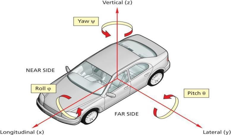
This protocol specifies the AEB City and AEB Inter-
Urban test procedures which are part of the Safety Assist
assessment, respectively. For AEB City, only the CCRs
scenario is applicable where the AEB functionality at
lower speed is tested.

For AEB Inter-Urban, the system is tested in one scenario
(CCRm). For this type of AEB system, the AEB
functionality is assessed.

2       DEFINITIONS
In this protocol, references are made to the following
terms, namely:

Peak Braking Coefficient (PBC) – the measure of tyre to
road surface friction based on the maximum deceleration
of a rolling tyre, measured using the American Society for
Testing and Materials (ASTM) E1136-10 (2010) standard
reference test tyre, in accordance with ASTM Method E
1337-90 (reapproved 1996), at a speed of 64.4km/h,
without water delivery.

Autonomous Emergency Braking (AEB) – braking that
is applied automatically by the vehicle in response to the
detection of a likely collision to reduce the vehicle speed
and potentially avoid the collision.

Dynamic Brake Support (DBS) – a system that further
amplifies the driver braking demand in response to the
detection of a likely collision to achieve a greater
deceleration than would otherwise be achieved for the
braking demand in normal driving conditions.

                            3
Car-to-Car Rear Stationary (CCRs) – a collision in
which a vehicle travels forwards towards another
stationary vehicle and the frontal structure of the vehicle
strikes the rear structure of the other.

Car-to-Car Rear Moving (CCRm) – a collision in which
a vehicle travels forwards towards another vehicle that is
travelling at constant speed and the frontal structure of the
vehicle strikes the rear structure of the other.

Vehicle under test (VUT) – the vehicle tested according
to this protocol with a pre-crash collision mitigation or
avoidance system on board.

Vehicle width – the widest point of the vehicle ignoring
the rear-view mirrors, side marker lamps, tyre pressure
indicators, direction indicator lamps, position lamps,
flexible mud-guards and the deflected part of the tyre side-
walls immediately above the point of contact with the
ground.

EURO Vehicle Target (EVT) – refers to the vehicle
target used in this protocol.

Time To Collision (TTC) – the remaining time before the
VUT strikes the EVT, assuming that the VUT and EVT
would continue to travel with the speed it is travelling.

TAEB – the time where the AEB system activates.
Activation time is determined by identifying the last data
point where the filtered acceleration signal is below -1

                             4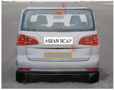
m/s2, and then returning to the point in time where the
acceleration first crossed -0.3 m/s2.

TFCW – the time where the audible warning of the FCW
starts. The starting point is determined by audible
recognition.

Vimpact – the speed at which the VUT hits the EVT.

Vrel_impact – the relative speed at which the VUT hits the
EVT by subtracting the velocity of the EVT from Vimpact
at the time of collision.

3      REFERENCE SYSTEM

3.1    Convention

3.1.1 For both VUT and EVT, ASEAN NCAP shall use
the convention specified in ISO 8855:1991 in which the x-
axis points toward the front of the vehicle, the y-axis
toward the left and the z-axis upward (right hand system),
with the origin at the most forward point on the centreline
of the VUT for dynamic data measurements as shown in
Figure 1.

3.1.2 Viewed from the origin, roll, pitch and yaw rotate
clockwise around the x, y and z axes respectively.
Longitudinal refers to the component of the measurement
along the x-axis, lateral the component along the y-axis
and vertical of the component along the z-axis.

                            5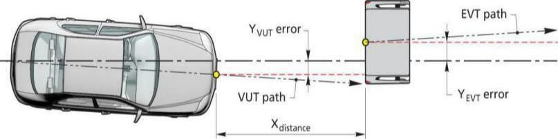
3.1.3 This reference system should be used for both left-
hand and right-hand drive vehicles tested.

        Figure 1: Coordinate system and notation

3.2     Lateral Offset

3.2.1 The lateral offset is determined as the lateral distance
between the centre of the front of the VUT and the centre
of the rear of the EVT when measured in parallel to the
intended straight lined path as shown in the figure below.

Lateral offset = YVUT error + YEVT error

                              6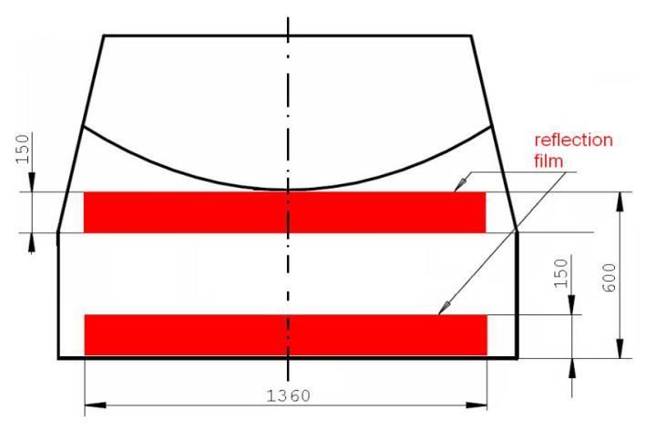
Figure 2: Lateral offset

4      MEASURING EQUIPMENT

4.1      Sample and record
A sample and record of all dynamic data at a frequency of
at least 100Hz are kept. They shall be synchronized using
the DGPS time stamp the EVT data with that of the VUT.

4.2    Measurements and Variables

4.2.1 Time                                  T
- CCRs and CCRm: T0 equals TTC = 4s         T0

- TAEB, time where AEB activates            TAEB
- TFCW, time where FCW activates            TFCW
- Timpact, time where VUT impacts EVT       Timpact

4.2.2 Position of the VUT
during the entire test                      XVUT, YVUT

4.2.3 Position of the EVT
during the entire test                      XEVT, YEVT

                            7
4.2.4 Speed of the VUT
during the entire test VVUT
- Vimpact, speed when VUT impacts EVT Vimpact
- Vrel_impact, relative speed when
VUT impacts EVT Vrel_impact
4.2.5 Speed of the EVT
during the entire test VEVT
4.2.6 Yaw velocity of the VUT during the entire test
4.2.7 Yaw velocity of the EVT during the entire test
4.2.8 Acceleration of the VUT
during the entire test AVUT
4.2.9 Acceleration of the EVT
during the entire test AEVT
4.3 Measuring Equipment
4.3.1 Equip the VUT and EVT with data measurement and
acquisition equipment to sample and record data with an
accuracy of at least.
- VUT and EVT speed of 0.1km/h;
- VUT and EVT lateral and longitudinal position to
0.03m;
- VUT and EVT yaw rate to 0.1°/s;
- VUT and EVT longitudinal acceleration to 0.1m/s²;
- VUT steering wheel velocity to 1.0°/s.
84.4 Data Filtering
4.4.1 Filter the measured data as follows:
4.4.1.1 Position and speed are not filtered and are used in
their raw state.
4.4.1.2 Acceleration with a 12-pole phaseless Butterworth
filter with a cut off frequency of 10Hz.
4.4.1.3 Yaw rate with a 12-pole phaseless Butterworth
filter with a cut off frequency of 10Hz.
4.4.1.4 Force with a 12-pole phaseless Butterworth filter
with a cut off frequency of 10Hz.
5 EURO NCAP VEHICLE TARGET
5.1 Specification
5.1.1 Conduct the tests in this protocol using the EURO
NCAP Vehicle Target V1 (EVT) as shown in Figure 3
below. The EVT replicates the visual, radar, LIDAR and
PMD attributes of a typical M1 passenger vehicle, and is
impactable at differential speeds up to 50km/h without
causing damage to the EVT.
9Figure 3: Euro NCAP Vehicle Target (EVT)
5.1.2 To ensure repeatable results, the propulsion system
and EVT must meet the requirements as detailed in
ANNEX A.
5.1.3 The EVT is designed to work with the following types
of sensors:
Radar (24 and 77 GHz)
LIDAR
Camera
PMD
Where a manufacturer believes that the EVT is suitable for
another type of sensor system other than used by the VUT
but is not listed above, the manufacturer is asked to contact
the ASEAN NCAP Secretariat.
106 TEST CONDITIONS
6.1 Test Track
6.1.1 Conduct tests on a dry (no visible moisture on the
surface), uniform, solid-paved surface with a consistent
slope between level and 1%. The test surface shall have a
minimal peak braking coefficient (PBC) of 0.9.
6.1.2 The surface must be paved and may not contain any
irregularities (e.g. large dips or cracks, manhole covers or
reflective studs) that may give rise to abnormal sensor
measurements within a lateral distance of 3.0m to either
side of the test path and with a longitudinal distance of
30m ahead of the VUT when the test ends.
6.1.3 The presence of lane markings is allowed. However,
testing may only be conducted in an area where typical
road markings depicting a driving lane may not be parallel
to the test path within 3.0m either side. Lines or markings
may cross the test path, but may not be present in the area
where AEB activation is expected.
6.2 Weather Conditions
6.2.1 Conduct tests in dry conditions with ambient
temperature above 5°C and below 40°C.
6.2.2 No precipitation shall be falling and horizontal
visibility at ground level shall be greater than 1km. Wind
speeds shall be below 10m/s to minimize EVT and VUT
disturbance.
116.2.3 Natural ambient illumination must be homogenous
in the test area and in excess of 2000 lux for daylight
testing with no strong shadows cast across the test area
other than those caused by the VUT or EVT. Ensure
testing is not performed driving towards, or away from the
sun when there is direct sunlight.
6.3 Surroundings
6.3.1 Conduct testing such that there are no other vehicles,
highway furniture, obstructions, other objects or persons
protruding above the test surface that may give rise to
abnormal sensor measurements within a lateral distance of
3.0m to either side of the test path and within a
longitudinal distance of 30m ahead of the VUT when the
test ends (Figure 4).
6.3.2 Test areas where the VUT needs to pass under
overhead signs, bridges, gantries or other significant
structures are not permitted.
Figure 4: Free surroundings
126.3.3 The general view ahead and to either side of the test
area shall comprise of a wholly plain man-made or natural
environment (e.g. further test surface, plain coloured
fencing or hoardings, natural vegetation or sky etc.) and
must not comprise any highly reflective surfaces or
contain any vehicle-like silhouettes that may give rise to
abnormal sensor measurements.
6.4 VUT Preparation
6.4.1 AEB and FCW System Settings
6.4.1.1 Set any driver configurable elements of the AEB
and/or FCW system (e.g. the timing of the collision
warning or the braking application if present) to the
middle setting or midpoint and the next latest setting
similar to the examples shown in Figure 5.
Setting 1
Setting 2
Early Setting 1 Setting 2 Setting 3 Late
Setting 1 Setting 2 Setting 3 Setting 4
Figure 5: AEB and/or FCW system setting for testing
136.4.2 Tyres
Perform the testing with new original fitment tyres of the
make, model, size, speed and load rating as specified by
the vehicle manufacturer. It is permitted to change the
tyres which are supplied by the manufacturer or acquired
at an official dealer representing the manufacturer if those
tyres are identical in make, model, size, speed and load
rating to the original fitment. Inflate the tyres to the
vehicle manufacturer's recommended cold tyre inflation
pressure(s). Use inflation pressures corresponding to least
loading normal condition.
Run-in tyres according to the tyre conditioning procedure
specified in 8.1.3. After running-in maintain the run-in
tyres in the same position on the vehicle for the duration
of the testing.
6.4.3 Wheel Alignment Measurement
The vehicle should be subject to a vehicle (in-line)
geometry check to record the wheel alignment set by the
OEM. This should be done with the vehicle in kerb weight.
6.4.4 Unladen Kerb Mass
6.4.4.1 Fill up the tank with fuel to at least 90% of the
tank’s capacity of fuel.
6.4.4.2 Check the oil level and top up to its maximum level
if necessary. Similarly, top up the levels of all other fluids
to their maximum levels if necessary.
146.4.4.3 Ensure that the vehicle has its spare wheel on
board, if fitted, along with any tools supplied with the
vehicle. Nothing else should be in the car.
6.4.4.4 Ensure that all tyres are inflated according to the
manufacturer’s instructions for the appropriate loading
condition.
6.4.4.5 Measure the front and rear axle masses and
determine the total mass of the vehicle. The total mass is
the ‘unladen kerb mass’ of the vehicle. Record this mass
in the test details.
6.4.4.6 Calculate the required ballast mass, by subtracting
the mass of the test driver and test equipment from the
required 200 kg interior load.
6.4.5 Vehicle Preparation
6.4.5.1 Fit the on-board test equipment and
instrumentation in the vehicle. Also fit any associated
cables, cabling boxes and power sources.
6.4.5.2 Place weights with a mass of the ballast mass. Any
items added should be securely attached to the car.
6.4.5.3 With the driver in the vehicle, weigh the front and
rear axle loads of the vehicle.
6.4.5.4 Compare these loads with the “unladen kerb mass”
156.4.5.5 The total vehicle mass shall be within ±1% of the
sum of the unladen kerb mass, plus 200kg. The front/rear
axle load distribution needs to be within 5% of the
front/rear axle load distribution of the original unladen
kerb mass plus full fuel load. If the vehicle differs from
the requirements given in this paragraph, items may be
removed or added to the vehicle which has no influence
on its performance. Any items added to increase the
vehicle mass should be securely attached to the car.
6.4.5.6 Repeat paragraphs 6.4.5.3 and 6.4.5.4 until the
front and rear axle loads and the total vehicle mass are
within the limits set in paragraph 6.4.5.5. Care needs to be
taken when adding or removing weight in order to
approximate the original vehicle inertial properties as
close as possible. Record the final axle loads in the test
details. Record the axle weights of the VUT in the ‘as
tested’ condition.
7 MANUFACTURER DATA
7.1 Manufacturer Supplied Data
7.1.1 The vehicle manufacturer is required to provide
ASEAN NCAP Secretariat with the colour data (expected
impact speeds are not required) detailing the performance
of the vehicle in the CCRs and CCRm scenarios for all
overlap and impact speed combinations. The prediction is
to be done for both AEB and FCW system tests where
applicable.
167.1.2 All data must be supplied by the manufacturer
before any testing begins, preferably with delivery of the
test vehicle(s).
7.1.3 Data shall be provided for each grid point
according to the following colour scheme for AEB City
(CCRs 10-60km/h) and for AEB Inter-Urban (CCRs 30-
60km/h & CCRm 30-60km/h):
177.2 Absence of Manufacturer Data
7.2.1 Where predicted data is NOT provided by the
vehicle manufacturer, ALL grid points are to be tested by
ASEAN NCAP laboratory, considering symmetry.
7.2.2 For AEB systems tests, when there is complete
avoidance, the subsequent test speed for the next test is
increased by 10km/h. When there is contact, first perform
a test at a test speed of 5km/h less than the test speed where
contact occurred. After this, continue to perform the
remainder of the tests with speed increments of 5km/h by
repeating section 8.3.1 to 8.4.3. Stop testing when the
speed reduction seen in the test is less than 5km/h.
8 TEST PROCEDURE
8.1 VUT Pre-test Conditioning
8.1.1 General
8.1.1.1 A car is used as delivered to the test laboratory.
8.1.1.2 If requested by the vehicle manufacturer, drive a
maximum of 100km on a mixture of urban and rural roads
with other traffic and roadside furniture to ‘calibrate’ the
sensor system. Avoid harsh acceleration and braking.
8.1.2 Brakes
8.1.2.1 Condition the vehicle’s brakes in the following
manner:
18Perform ten stops from a speed of 56km/h with an
average deceleration of approximately 0.5 to 0.6g.
Immediately following the series of 56km/h stops,
perform three additional stops from a speed of 72km/h,
each time applying sufficient force to the pedal to operate
the vehicle’s antilock braking system (ABS) for the
majority of each stop.
Immediately following the series of 72km/h stops,
drive the vehicle at a speed of approximately 72km/h for
five minutes to cool the brakes.
Initiation of the first test shall begin within two
hours after completion of the brake conditioning.
8.1.3 Tyres
8.1.3.1 Condition the vehicle’s tyres in the following
manner to remove the mould sheen:
Drive around a circle of 30m in diameter at a speed
sufficient to generate a lateral acceleration of
approximately 0.5 to 0.6g for three clockwise laps
followed by three anticlockwise laps.
Immediately following the circular driving, drive
four passes at 56km/h, performing ten cycles of a
sinusoidal steering input in each pass at a frequency of
1Hz and amplitude sufficient to generate a peak lateral
acceleration of approximately 0.5 to 0.6g.
Make the steering wheel amplitude of the final
cycle of the final pass double that of the previous inputs.
8.1.3.2 In case of instability in the sinusoidal driving,
reduce the amplitude of the steering input to an
appropriately safe level and continue the four passes.
198.1.4 AEB System Check
8.1.4.1 Before any testing begins, perform a maximum of
ten runs at the lowest test speed the system is supposed to
work, to ensure proper functioning of the system.
8.2 Test Scenarios
8.2.1 The performance of the VUT AEB system is
assessed in the CCRs and CCRm scenarios as shown in
Figures 6a and b.
8.2.2 For testing purposes, assume a straight-line path
equivalent to the centreline of the lane in which the
collision occurred, hereby known as the test path. Control
the VUT with driver inputs or using alternative control
systems that can modulate the vehicle controls as
necessary to perform the tests.
Figure 6a: CCRs scenario
20Figure 6b: CCRm scenario
8.2.3 The CCRs and CCRm tests will be performed with
5km/h or 10km/h incremental steps (see 7.4.4) within the
speed ranges shown in the tables below.
CCRs
AEB ONLY
AEB City 10 - 60 km/h
AEB Inter- Urban 30 - 60 km/h
CCRm
AEB ONLY
AEB Inter- Urban 30 - 60 km/h
8.2.4.1 The desired deceleration of the EVT shall be
reached within 1.0 seconds and shall not vary by more
than ± 0.25 m/s2 of the desired level at any point in time
until the end of test.
218.3 Test Conduct
8.3.1 Before every test run, drive the VUT around a circle
of maximum diameter 30m at a speed less than 10km/h for
one clockwise lap followed by one anticlockwise lap, and
then maneuver the VUT into position on the test path. If
requested by the OEM, an initialisation run may be
included before every test run. Bring the VUT to a halt and
push the brake pedal through the full extent of travel and
release.
8.3.2 For vehicles with an automatic transmission, select
D. For vehicles with a manual transmission, select the
highest gear where the RPM will be at least 1500 at the
test speed. If fitted, a speed limiting device or cruise
control may be used to maintain the VUT speed unless the
vehicle manufacturer shows that there are interferences of
these devices with the AEB system in the VUT. Apply
only minor steering inputs as necessary to maintain the
VUT tracking along the test path.
8.3.3 Perform the first test a minimum of 90s and a
maximum of 10 minutes after completing the tyre
conditioning, and subsequent tests after the same time
period. If the time between consecutive tests exceeds 10
minutes repeat the tyre conditioning procedures and
recommence testing.
8.3.4 Between tests, maneuver the VUT at a maximum
speed of 50km/h and avoid riding the brake pedal and
harsh acceleration, braking or turning unless strictly
necessary to maintain a safe testing environment.
228.4 Test Execution
8.4.1 Accelerate the VUT and EVT (if applicable) to the
respective test speeds.
8.4.2 The test shall start at T0 (4s TTC) and is valid when
all boundary conditions are met between T0 and
TAEB/TFCW:
Test speed + 1.0
- Speed of VUT (GPS-speed)
km/h
Test speed ± 1.0
- Speed of EVT (GPS-speed)
km/h
- Lateral deviation from test path 0 ± 0.1 m
- Yaw velocity 0 ± 1.0 °/s
- Steering wheel velocity 0 ± 15.0 °/s
8.4.3 The end of a test is considered when one of the
following occurs:
- VVUT = 0km/h
- VVUT < VEVT
- Contact between VUT and EVT
8.4.4 For AEB systems tests, when there is complete
avoidance, the subsequent test speed for the next test is
increased by 10km/h. When there is contact, first perform
a test at a test speed 5km/h less than the test speed where
contact occurred. After this test continue to perform the
remainder of the tests with speed increments of 5km/h by
repeating section 7.3.1 to 7.4.3. Stop testing when the
speed reduction seen in the test is less than 5km/h.
23For manual or automatic accelerator control, it needs to be
assured that during automatic brake the accelerator pedal
does not result in an override of the system.
8.4.5 Braking will be applied that results in a maximum
brake level of -4 m/s2 - 0.25 m/s2 when applied in a non-
threat situation. The particular brake profile to be applied
(pedal application rate applied in 200ms (max. 400mm/s)
and pedal force) shall be specified by the manufacturer.
When the brake profile provided by the manufacturer
results in a higher brake level than allowed, the iteration
steps as described in ANNEX B will be applied to scale
the brake level to -4 m/s2 - 0.25 m/s2.
8.4.6 When no brake profile is provided, the default brake
profile as described in ANNEX B will be applied.
24ANNEX A
EVT SPECIFICATIONS
The Euro NCAP Vehicle Target (EVT) which is used for
AEB City and Inter-Urban testing is developed to have the
radar signature, reflectivity and visual signature
comparable to that of a ‘C’ segment vehicle in order to aid
radar, LIDAR, PMD and camera detection respectively.
The EVT is build up out of a balloon structure that is
covered by a PVC cover on which a vehicle is printed. For
both a detailed description is provided within this
ANNEX.
A.1 Balloon Vehicle Structure
The balloon structure consists of polyester, polyethylene,
PA 6.6, polychloroprene and nylon. The outer dimensions
of the balloon structure are 1600 mm wide and 1350 mm
tall with a tolerance of ± 10mm. More detailed dimensions
can be found in the front and side view in Figure A.1-1
and Figure A.1-2.
25Figure A.1-1: Balloon structure front view
26Figure A.1-2: Balloon structure side view
A.1.1 Radar Absorption Mat
At the impact side and rear of the balloon target a layer of
radar absorbing material is applied. The exact position and
dimensions of these radar absorption mats are shown in
Figure A.1.1-1 and Figure A.1.1-2. The material
properties of the radar absorption mat are detailed in
paragraph A.1.1.1
27Figure A.1.1-1: Rear and side view of balloon structure
including the rear radar absorption mat
Figure A.1.1-2: Section B-B and side view of balloon
structure including the front radar absorption mat
28A.1.1.1 Material Properties The radar absorption mats are according to ASTM-D 1692-68 and are made of Polyurethane foam EC 712 with the attenuation in dB as shown in the table below. The absorber can be loaded with 2 mW per mm ². Footprint Thickness
Figure A.1.2-1: Side view of balloon structure including
                  the bumper element

Figure A.1.2-2: Top, side, front and ISO view of bumper
                        element
                          30
A.1.3 Radar Reflector
Within the bumper element, a radar reflector is
incorporated. The reflector has an inside edge length of
55mm and imitates a surface of 2.5m² at 77GHz. The
position and orientation of the radar reflector within the
bumper element is shown in Figure A.1.3-1.
Figure A.1.3-1: Front and side view of the radar reflector
within the bumper element
A.1.4 Reflective Film
In addition to the radar reflector, two reflective films of
1360mm wide and 150mm high are glued onto the bumper
element as shown in Figure A.1.4-1. The films are made
of polyester and are provided by Bruin Plastic Company
INC (http://www.bruinplastics.com/index.html) under the
product name of Energy Shield 200 - 10 oz. If another
31reflection film is used, the reflection characteristics have
to be identical as for the Energy Shield 200.
Figure A.1.4-1: Front view of the reflective film on the
bumper element
A.2 EVT Outer Cover
The balloon structure is covered by a PVC cover with a
picture of an actual car is printed. The cover material is
produced by Complot Papier Union
(http://www.complottpapierunion.de/) with the product
name PowerJet Poly Banner Frontlit 550 B1, which is a
550 g/m² tarpaulin.
The generic artwork that needs to be printed onto the EVT
cover can be provided by ASEAN NCAP. The artwork
should be printed full colour to at least (100dpi) to give
the correct contrast in colours of the vehicle rear.
32A.2.1 Retro- Reflective Film
Retro-Reflective film is attached to the cover to replicate
the reflectivity of the rear lights as shown in Figure A.2.1-
1. The retro-reflective tape for the lights is produced
according to the norm ECE 104. The top rear light retro-
reflection film has to be in the upper middle of the car. The
left and right have to been stuck congruent to the normal
back lights and have to look like the original one.
Figure A.2.1-1: Front view of the EVT with the location
of the retro-reflective tape
A.2.2 Radar Absorption Mat
At the impact side of the EVT a layer of radar absorbing
material is applied to the bottom of the target to replicate
the shadow between the wheels. The material of the
absorption mat is the same as specified in A.1.1. The
33dimensions of the mat are shown in Figure A.2.2-1 with a
thickness of 20mm. The absorption mat is sewn into the
EVT outer cover and is behind three layers of leather
which were stuck together.
Figure A.2.2-1: Left, Front view of the EVT with the
location of the lower radar absorption mat.
Right, different layers of absorption mat
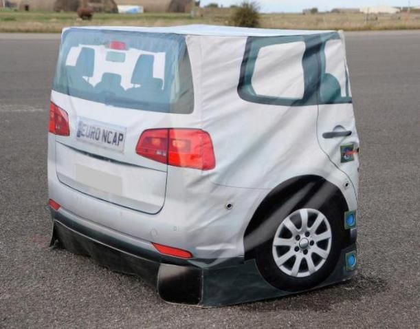
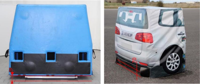
34A.3 EVT Test Position
The ground clearance of the balloon structure for testing
is set to 70mm as shown in Figure A.3-1.
Figure A.3-1: Front view of the EVT showing the ground
clearance
35ANNEX B
BRAKE APPLICATION PROCEDURE
The braking input characterisation test determines the
brake pedal displacement and force necessary to achieve a
vehicle deceleration typical of that produced by a typical
real-world driver in emergency situations.
B.1 Definitions
TBRAKE - The point in time where the brake pedal
displacement exceeds 5mm.
T-6m/s2 - The point in time is defined as the first data point
where filtered, zeroed and corrected longitudinal
acceleration data is less than -6m/s2.
T-2m/s², T-4m/s² - similar to T-6m/s².
B.2 Measurements
Measurements and filters to be applied as described in
Chapter 4 of this protocol.
B.3 Brake Characterization Procedure
First perform the brake and tyre conditioning tests as
described in 7.1.2 and 7.1.3. The brake input
characterisation tests shall be undertaken within 10
minutes after conditioning the brakes and tyres.
B.3.1 Brake Displacement Characterisation Tests
Push the brake pedal through the full extent of travel
and release.
36Accelerate the VUT to a speed in excess of 85km/h.
Vehicles with an automatic transmission will be driven in
D. For vehicles with a manual transmission select the
highest gear where the RPM will be at least 1500 at the
85km/h.
Release the accelerator and allow the vehicle to coast.
At a speed of 80 ± 1.0km/h initiate a ramp braking input
with a pedal application rate of 20±5mm/s and apply the
brake until a longitudinal acceleration of -7m/s2 is
achieved. For manual transmission vehicles, press the
clutch as soon as the RPM drops below 1500. The test
ends when a longitudinal acceleration of -7m/s2 is
achieved.
Measure the pedal displacement and applied force
normal to the direction of travel of the initial stroke of the
brake pedal, or as close as possible to normal as can be
repeatedly achieved.
Perform three consecutive test runs. A minimum time
of 90 seconds and a maximum time of 10 minutes shall be
allowed between consecutive tests. If the maximum time
of 10 minutes is exceeded, the tyre and brake conditioning
procedures shall be repeated before restarting the brake
pedal force characterisation tests.
Using second order curve fit and the least squares
method between T-2m/s², T-6m/s², calculate the pedal travel
value corresponding to a longitudinal acceleration of -4
m/s² (=D4, unit is m). Use data of at least three valid test
runs for the curve fitting.
This brake pedal displacement is referred to as D4 in
the next chapters.
37Using second order curve fit and the least squares
method between T-2m/s², T-6m/s², calculate the pedal force
value corresponding to a longitudinal acceleration of -4
m/s² (=F4, unit is N). Use data of at least three valid test
runs for the curve fitting.
This brake pedal force is referred to as F4 in the next
chapters.
B.3.3 Brake Force Confirmation and Iteration
Procedure
Accelerate the VUT to a speed of 80+1km/h.
Vehicles with an automatic transmission will be driven in
D. For vehicles with a manual transmission select the
highest gear where the RPM will be at least 1500 at the
80km/h.
Apply the brake force profile as specified in B.4,
triggering the input manually rather than in response to the
FCW. Determine the mean acceleration achieved during
the window from TBRAKE +1s TBRAKE +3s. If a mean
acceleration outside the range of -4-0.25m/s2 results, apply
the following method to ratio the pedal force applied.
F4new = F4original * (-4/mean acceleration), i.e. if
F4original results in a mean acceleration of -5m/s2, F4new
= F4original * -4 / -5
Repeat the brake force profile with this newly
calculated F4, determine the mean acceleration achieved
and repeat the method as necessary until a mean
acceleration within the range of -4-0.25m/s2 is achieved.
Three valid pedal force characteristic tests (with the
acceleration level being in the range as specified) are
required. A minimum time of 90 seconds and a maximum
time of 10 minutes shall be allowed between consecutive
38tests. If the maximum time of 10 minutes is exceeded, the
tyre and brake conditioning procedures shall be repeated
before restarting the brake pedal force characterisation
tests. This brake pedal force is referred as F4 in the next
chapters.
B.4 Brake Application Profile
Detect TFCW during the experiment in real-time.
Release the accelerator at TFCW + 1 s.
Perform displacement control for the brake pedal,
starting at TFCW + 1.2 s with a gradient of the lesser of 5 x
D4 or 400mm/s (meaning the gradient to reach pedal
position D4 within 200ms, but capped to a maximum
application rate of 400mm/s).
Monitor brake force during displacement control
and use second-order filtering with a cutoff frequency
between 20 and 100 Hz (online) as appropriate.
Switch to force control with a desired value of F4
when:
i. the value D4 as defined in B.3 is exceeded for the
first time,
ii. the force F4 as defined in B.3 is exceeded for the
first time, whichever is reached first.
The point in time where position control is switched
to force control is noted as Tswitch.
Maintain the force within boundaries of F4 ± 25% F4.
A stable force level should be achieved within a period of
200ms maximum after the start of force control.
Additional disturbances of the force over ± 25% F4 due to
further AEB interventions are allowed, as long as they
have a duration of less than 200ms.
39The average value of the force between TFCW + 1.4s
and the end of the test should be in the range of F4 ± 10
N.
40Editors
Yahaya Ahmad
Malaysian Institute of Road Safety Research (MIROS)
Ir. Dr. Khairil Anwar Abu Kassim (Adjunct. Prof)
Malaysian Institute of Road Safety Research (MIROS)
Mohd Hafiz Johari
Malaysian Institute of Road Safety Research (MIROS)
Salina Mustaffa
Malaysian Institute of Road Safety Research (MIROS)
Special Acknowledgement:
This protocol is based on Euro NCAP AEB Test Protocol
version 1.1 which is the intellectual property of Euro
NCAP. Permission is granted for this material to be
shared for non-commercial and educational purposes.
Copying of parts of the original text is by permission of
Euro NCAP.
4142
You can also read