24 GHz transceiver: BGT24LTR11 - Infineon Technologies
←
→
Page content transcription
If your browser does not render page correctly, please read the page content below
AN598

 24 GHz transceiver: BGT24LTR11
 Sense2GoL Pulse (Pulsed Doppler) – XENSIV™ 24 GHz low-power radar
 Shield using BGT24LTR11 for motion, speed and direction of movement
 detection

 Board version V3.0

 About this document
 Scope and purpose
 This application note describes the key features of Infineon’s BGT24LTR11 Shield, part of Infineon’s 24 GHz
 Sense2GoL Pulse radar system platform. The Shield is the evaluation platform for the 24 GHz low-power
 transceiver chip BGT24LTR11.
 1. The application note describes the hardware configuration and specifications of the sensor module in
 detail.
 2. The document also provides a guide to configure the hardware and implement simple radar applications
 with the firmware/software developed.

 Intended audience
 This document serves as a primer for users who want to get started with hardware design for speed and
 direction of movement detection using Doppler radar techniques at 24 GHz.

 Related documents
 Additional information can be found in the supplementary documentation provided with the Sense2GoL Pulse
 Kit in the Infineon Toolbox or from www.infineon.com/24GHz:
 • 24 GHz Radar Tools and Development Environment User Manual
 • Sense2GoL Pulse (Pulsed Doppler) Software User Manual
 • AN602 – Radar Baseboard XMC4700
 • AN605 – Radar Baseboard XMC4700 and BGT24LTR11 Shield with Arduino

 Application Note Please read the Important Notice and Warnings at the end of this document V2.0
 www.infineon.com page 1 of 37 2021-08-13
Sense2GoL Pulse (Pulsed Doppler) low-power radar Shield using BGT24LTR11
for motion, speed and direction of movement detection
Table of contents

Table of contents
About this document ....................................................................................................................... 1
Table of contents ............................................................................................................................ 2
List of figures ................................................................................................................................. 3
List of tables .................................................................................................................................. 4
1 Introduction .......................................................................................................................... 5
1.1 Key features ............................................................................................................................................. 6
1.2 Overview .................................................................................................................................................. 6
2 Getting started ...................................................................................................................... 8
2.1 Additional material ............................................................................................................................... 10
3 System specifications ............................................................................................................ 11
4 Hardware description – BGT24LTR11 Shield ............................................................................. 13
4.1 Overview ................................................................................................................................................ 13
4.2 Block diagram........................................................................................................................................ 14
4.3 Power supply ......................................................................................................................................... 16
4.4 EEPROM ................................................................................................................................................. 16
4.5 RF front end ........................................................................................................................................... 16
4.6 BGT24LTR11 – 24 GHz transceiver MMIC .............................................................................................. 17
4.7 Antennas ................................................................................................................................................ 18
4.8 Sample and Hold (S&H) circuitry .......................................................................................................... 19
4.8.1 Basic considerations on the S&H circuit ......................................................................................... 20
4.9 Analog baseband section ...................................................................................................................... 21
4.9.1 Baseband amplifier settings for Doppler radar .............................................................................. 23
5 System configuration and parameters ..................................................................................... 24
6 Power consumption analysis .................................................................................................. 27
7 External pin header connectors .............................................................................................. 28
8 Use cases and applications ..................................................................................................... 31
8.1 Human walking detection ..................................................................................................................... 31
9 Measurement results ............................................................................................................. 32
9.1 Velocity detection.................................................................................................................................. 32
9.2 Human movement detection................................................................................................................ 32
10 Frequency band and regulations ............................................................................................. 33
10.1 24 GHz regulations ................................................................................................................................ 33
10.2 Regulations in Europe ........................................................................................................................... 33
10.3 Regulations in the United States of America........................................................................................ 33
11 Authors ................................................................................................................................ 34
12 References ........................................................................................................................... 35
Revision history............................................................................................................................. 36

Application Note page 2 of 37 V2.0
 2021-08-13
Sense2GoL Pulse (Pulsed Doppler) low-power radar Shield using BGT24LTR11
for motion, speed and direction of movement detection
List of figures

List of figures
Figure 1 Sense2GoL Pulse demo board ............................................................................................................ 7
Figure 2 Steps 1 to 3 to get started with Sense2GoL Pulse demo board ......................................................... 8
Figure 3 Steps 4 to 6 to get started with Sense2GoL Pulse demo board ......................................................... 9
Figure 4 Steps 7 to 9 to get started with the Sense2GoL Pulse demo board ................................................ 10
Figure 5 BGT24LTR11 Shield board with main components ......................................................................... 13
Figure 6 Block diagram – Sense2GoL Pulse .................................................................................................... 15
Figure 7 Block diagram – power supply concept ........................................................................................... 16
Figure 8 EEPROM block diagram..................................................................................................................... 16
Figure 9 RF front-end overview (top) .............................................................................................................. 17
Figure 10 Block diagram – BGT24LTR11 ........................................................................................................... 17
Figure 11 2D radiation pattern for array antennas........................................................................................... 18
Figure 12 S&H circuitry ...................................................................................................................................... 19
Figure 13 S&H circuit signals ............................................................................................................................. 19
Figure 14 Hold capacitor calculation ................................................................................................................ 20
Figure 15 Baseband amplifier chain – block diagram ...................................................................................... 21
Figure 16 Baseband amplifier chain – schematics ........................................................................................... 21
Figure 17 IF low-gain and high-gain signals for an input of 100 Hz, 1 mV input signal ................................... 22
Figure 18 Baseband frequency response for low-gain and high-gain stages ................................................. 22
Figure 19 Frame structure and terminology .................................................................................................... 24
Figure 20 Pulse timing configuration................................................................................................................ 26
Figure 21 On/Off timing diagram – Saleae Logic analyzer plot ....................................................................... 27
Figure 22 External headers – P1, P2, P3, P4,P5 and P6 .................................................................................... 28
Figure 23 Human walking – use-case visualization.......................................................................................... 31
Figure 24 Smart door opener – use-case visualization .................................................................................... 31
Figure 25 Speed measurements (Doppler simulator vs radar) ........................................................................ 32
Figure 26 Motion detection area for a human target area ............................................................................... 32

Application Note page 3 of 37 V2.0
 2021-08-13
Sense2GoL Pulse (Pulsed Doppler) low-power radar Shield using BGT24LTR11
for motion, speed and direction of movement detection
List of tables

List of tables
Table 1 Sense2GoL Pulse (Pulsed Doppler) module performance specifications ....................................... 11
Table 2 Baseband amplifiers to MCU pin connections ................................................................................. 23
Table 3 Baseband amplifier components and settings ................................................................................ 23
Table 4 Doppler shift frequencies for different speeds using 24 GHz radar ................................................. 23
Table 5 System parameters, symbols and units ........................................................................................... 25
Table 6 Power consumption overview .......................................................................................................... 27
Table 7 External headers (P1) – pin description............................................................................................ 28
Table 8 External headers (P2) – pin description............................................................................................ 29
Table 9 External headers (P3) – pin description............................................................................................ 29
Table 10 External headers (P4) – pin description............................................................................................ 29
Table 11 External headers (P5) – pin description............................................................................................ 29
Table 12 External headers (P6) – pin description............................................................................................ 29
Table 13 Recommended settings for human motion detection .................................................................... 31

Application Note page 4 of 37 V2.0
 2021-08-13
Sense2GoL Pulse (Pulsed Doppler) low-power radar Shield using BGT24LTR11
for motion, speed and direction of movement detection
Introduction

1 Introduction
The Sense2GoL Pulse radar system is a demo platform for Infineon’s 24 GHz silicon-germanium (SiGe)
BGT24LTR11 radar chipset. It consists of two boards – the microcontroller board: Radar Baseboard XMC4700,
and a radar front-end board: BGT24LTR11 Shield. This document focuses on the BGT24LTR11 Shield for a
Pulsed Doppler implementation. Detailed information about the Radar Baseboard XMC4700 can be found in the
corresponding application note (AN602).
The system is designed to allow customers to carry out prototyping and system integrations, as well as initial
product feature evaluations. The platform is a low-power solution for detecting speed and direction of
movement (approaching or retreating) of a human. These features of the board make it suitable for various
applications such as motion detection, presence sensing, etc. These use cases target applications such as
smart lighting, smart doors, smart devices, etc.
The main radar technique used on the platform is Continuous Wave (CW/Doppler) radar for velocity estimation.
The principle of the Doppler effect is used. The radar transmits a constant-frequency signal continuously and
receives the echo signal from the moving target. The change in phase between the transmitted and received
signal is used to calculate the target’s velocity.
Sample and Hold (S&H) circuitry is implemented for low-power consumption. Two-stage low-noise baseband
amplification stages are used for enhanced target detection. The baseband section can be configured by re-
soldering for different cut-off frequencies and gain requirements of different applications. The module also
offers the possibility of using a battery for operation.
The module provides a complete radar system evaluation platform including demonstration software and a
basic graphical user interface (GUI) which can be used to display and analyze acquired data in time and
frequency domain. An onboard debugger with licensed firmware from SEGGER enables easy debugging over
USB. Infineon’s powerful, free-of-charge toolchain DAVE™ can be used for programming the XMC4700
microcontroller. The system also features integrated micro-strip patch antennas on the PCB with design data,
thereby eliminating antenna design complexity at the user end.
This application note describes the key features and hardware configuration of the BGT24LTR11 Shield in
detail.

Application Note page 5 of 37 V2.0
 2021-08-13
Sense2GoL Pulse (Pulsed Doppler) low-power radar Shield using BGT24LTR11
for motion, speed and direction of movement detection
Introduction

1.1 Key features
The primary features of the Sense2GoL Pulse radar system are as follows:

 • Detects motion, speed and direction of movement (approaching or retreating) for a human

 • Extremely low power consumption (using S&H circuitry)

 • Two-board topology for RF section and microcontroller sections
 • Two configurable analog amplifier stages for the RX channel
 • Micro-strip patch antennas with 10 dBi gain and 29 x 80 degrees Field of View (FoV)
 • Multiple power supply possibilities – micro-USB, external power supply or LiPo battery

 • Compatible with Arduino for ease of use and prototyping

 • Operates in different weather conditions including rain, fog, etc.

 • Can be hidden in the end application as it detects through non-metallic materials

Note: The platform serves as a demonstrator platform with the software to perform simple motion
 sensing. The test data in this document show typical performance of Infineon-produced platforms.
 However, board performance may vary depending on the PCB manufacturer and specific design
 rules imposed and components used.

1.2 Overview
The platform is a stack-up of two boards – BGT24LTR11 Shield (radar front-end) and Radar Baseboard XMC4700
(for signal processing).
The Sense2GoL Pulse radar system consists of the following key components:

 • BGT24LTR11 – highly integrated 24 GHz transceiver IC with one transmitter (TX) and one receiver (RX)
 • XMC4700 – 32-bit Arm® Cortex®-M4 based microcontroller for signal processing

 • TS5A4596 – SPST S&H switches for low power consumption

 • IRLHS2242 – MOSFET for duty-cycle operation
 • INA226 – current shunt and power monitors for current consumption estimation
 • MCP73831T – battery manager for charging and using the battery

 • CW1280T – EEPROM to store board identifier information

 • MOLEX 047571001 – SD card reader for storing raw data
 • XMC4200 – 32-bit Arm® Cortex®-M4 based microcontroller for debugging

Application Note page 6 of 37 V2.0
 2021-08-13
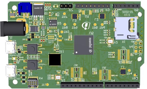
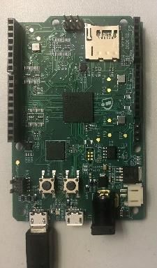
Sense2GoL Pulse (Pulsed Doppler) low-power radar Shield using BGT24LTR11
for motion, speed and direction of movement detection
Introduction

 Radar Sense2GoL
 BGT24LTR11
 Baseboard Pulse
 Shield Distance2GoL
 XMC4700

Figure 1 Sense2GoL Pulse demo board

Note: The BGT24LTR11 Shield in Sense2GoL Pulse platform is assembled for Pulsed Doppler operation.

The circuitry for the BGT24LTR11 Shield (Pulsed Doppler) is designed to carry out Doppler detection with low
power consumption. The analog I/Q signals from the MMIC act as inputs to the S&H circuitry. When the switch is
closed (sample mode), the hold capacitor follows the I/Q analog signal of the MMIC and charges to its peak
value. When the switch is opened (hold mode), the hold capacitor holds the sampled voltage. This
implementation allows us to turn the BGT24LTR11 off during the “hold time” and hence save power. The
S&H_EN signal from the Radar Baseboard XMC4700 controls the on/off timing of the switches. The output of the
S&H circuitry is amplified and filtered by the baseband section. These amplified I/Q signals are then routed to
the Radar Baseboard XMC4700 via connectors for signal processing. It also provides the control signals for the
BGT24LTR11 Shield board via connectors.

Application Note page 7 of 37 V2.0
 2021-08-13
Sense2GoL Pulse (Pulsed Doppler) low-power radar Shield using BGT24LTR11
for motion, speed and direction of movement detection
Getting started

2 Getting started
This section provides a step-by-step quick process to get started with the Sense2GoL Pulse board. Some of the
steps are optional for going deeper into the analysis of the board, the firmware and the extracted signals.
 d

 STEP 1 STEP 2 STEP 3

 Box contents Infineon Toolbox Install Sense2GoL Pulse kit
 • BGT24LTR11 Shield
 • Go to: • Open “Infineon Toolbox ”.
 (Pulsed Doppler)
 Infineon Products and Tools -
 • Radar Baseboard Infineon Toolbox • Click on the “Manage tools” tab.
 XMC4700
 • Search for “Sense2GoL Pulse Kit”.
 • Micro-USB cable
 • Click on “Infineon Toolbox
 Launcher” link

 • Click on “Install”.

 • Scroll down and click on
 the “Download now” button.

 • “Accept” the license agreement.
 • Run the “Run the
 “infineon-toolbox- • Finish installation.
 setup.exe” file.

 • “Accept” the license
 agreement.

 • Finish installation. Create a
 desktop shortcut.

Figure 2 Steps 1 to 3 to get started with Sense2GoL Pulse demo board

Application Note page 8 of 37 V2.0
 2021-08-13
Sense2GoL Pulse (Pulsed Doppler) low-power radar Shield using BGT24LTR11 for motion, speed and direction of movement detection Getting started STEP 4 STEP 5 STEP 6 Optional Optional Download HW/SW Connect board Firmware update package • Insert micro-USB cable into • Download and install SEGGER • Open “Infineon Toolbox ”. the Radar Baseboard J-Link USB driver for Windows: XMC4700 “debug” port. www.segger.com/downloads/jlink/#J- • Click on “Sense2GoLPulse LinkSoftwareAndDocumentationPack Kit”. • Connect board as STEP 5 • Follow the instructions • Open Infineon Toolbox Radar mentioned on the left tab GUI Device Flash Firmware. (2. Getting Started). • Insert the USB connector • Save the set-up file and run into the PC’s USB port. it. • Select Device “Sense2GoL Pulse” and select Firmware S2GLP-HW-SW.exe “S2GLP_Pulsed_Doppler.hex ” If the device driver is not recognized: Right-click on “My Computer” • Browse to the preferred Manage Device Manager location to store the files. Other devices Right-click on “Unknown device” Update Driver Software Browse Firmware_Software XMC_Serial_Driver. • Click on “Flash Firmware”. Figure 3 Steps 4 to 6 to get started with Sense2GoL Pulse demo board Application Note page 9 of 37 V2.0 2021-08-13
Sense2GoL Pulse (Pulsed Doppler) low-power radar Shield using BGT24LTR11 for motion, speed and direction of movement detection Getting started STEP 7 STEP 8 ST EP 9 Optional Optional View and edit source code Radar GUI MATLAB interface • Download and install the • Disconnect micro-USB cable • Go to: Firmware_Software DAVE™ IDE tool: from “debug” port and Communication Library connect it to “default” port. ComLib_Matlab_Interface https://infineoncommun ity.com/dave- Examples GettingStarted. download_ID645 Copy the path. • Go to Firmware_Software DAVE project. Unzip the • Open MATLAB. Paste the DAVE™ project files of your path in the top tab. choice. “extract_raw_data.m” file • Open Radar GUI will show up on the left tab. • Run DAVE™ IDE. • Connect board as STEP 8. • Import DAVE™ projects and debug. • Click on “Run” to see raw data. • Real-time data is now on your screen. Figure 4 Steps 7 to 9 to get started with the Sense2GoL Pulse demo board 2.1 Additional material The board comes with additional documentation for customer support. These documents can be found in the folders downloaded through Step 4 in Figure 3. They are: • Application Notes • Software User Manual • Altium PCB project • Schematics • Bill of Materials (BOM) • Production data • DAVE™ project and FW binary files • Radar GUI XMC settings files • 3D model files • Power consumption calculator Application Note page 10 of 37 V2.0 2021-08-13
Sense2GoL Pulse (Pulsed Doppler) low-power radar Shield using BGT24LTR11
for motion, speed and direction of movement detection
System specifications

3 System specifications
Table 1 gives the specification of the Sense2GoL Pulse (Pulsed Doppler) radar system.

 Table 1 Sense2GoL Pulse (Pulsed Doppler) module performance specifications
Parameter Unit Min. Typ. Max. Comments

 System performance
 Configurable by re-soldering
 the baseband section (Table 3)
 Detection speed km/h 0.3 5 10 and considering the sampling
 freqeuncy as well as the
 number of samples
 Detection distance m 0.1 15 20 Human target

 Power supply
 Supply voltage V 3.3 5 5.5 Supplied via the baseboard
 Supply current mA 50 All blocks on (only the Shield)

 Transmitter characteristics
 Transmitter frequency GHz 24.05 24.125 24.25
 Conditions:
 Effective Isotropic Radiated Power BGT POUT: +6 dBm
 dBm +14
 (EIRP) Loss (TXOUT to ant. input = 2 dB)
 Simulated ant. gain = +10 dBi

 Receiver characteristics
 Receiver frequency GHz 24.05 24.125 24.25
 IF conversion gain – Configurable by re-soldering
 dB 30
 (stage 1) the baseband section (Table 3)
 IF conversion gain – Configurable by re-soldering
 dB 59
 (stage 1 + stage 2) the baseband section (Table 3)
 -3 dB bandwidth – Configurable by re-soldering
 Hz 16 420
 (stage 1 + stage 2) the baseband section (Table 3)

 Antenna characteristics (simulated)
 Antenna type 1x4
 Horizontal – 3 dB beamwidth
 Degrees 80
 (HPBW)
 Elevation – 3 dB beamwidth
 Degrees 29
 (HPBW)
 Horizontal sidelobe level
 dB 13
 suppression
 Vertical sidelobe level suppression dB 13

Application Note page 11 of 37 V2.0
 2021-08-13
Sense2GoL Pulse (Pulsed Doppler) low-power radar Shield using BGT24LTR11
for motion, speed and direction of movement detection
System specifications

Note: The above specifications are indicative values based on typical datasheet parameters of
 BGT24LTR11 and simulation of several other parameters (antenna characteristics and baseband
 section) and can vary from module to module. The numbers above are not guaranteed indicators
 for module performance for all operating conditions.

Application Note page 12 of 37 V2.0
 2021-08-13
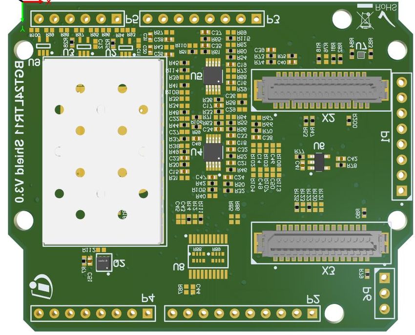
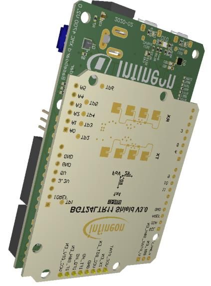
Sense2GoL Pulse (Pulsed Doppler) low-power radar Shield using BGT24LTR11
for motion, speed and direction of movement detection
Hardware description – BGT24LTR11 Shield

4 Hardware description – BGT24LTR11 Shield
This section presents a detailed overview of the BGT24LTR11 Shield hardware specifications, including the MMIC
considerations, power supply and board interfaces.

4.1 Overview
The radar shield is shown in Figure 5. It contains the following sections:

 • RF part – consists of the Infineon 24 GHz radar MMIC – BGT24LTR11 and includes micro-strip patch
 antennas for the TX and RX sections

 • S&H part – consists of SPST switches and hold capacitors to sample and hold the analog I/Q signals
 from the MMIC using the control signal S&H_EN

 • Analog amplifier part – smoothens the sampled I/Q signals from the S&H circuitry and amplifies them
 for the digital part

 • EEPROM part – stores data such as board identifier
 Arduino-compatible
 connectors

 Voltage level
 translator Connectors
 to Radar
 Baseboard
 PMOS switch

 LDO
 Metal
 shielding External pin
 headers
 BGT24LTR11
 MMIC

 EEPROM

 Arduino-compatible
 Operational amplifiers
 connectors
 (base band section)

 66 mm

 TX and RX
 antennas

Figure 5 BGT24LTR11 Shield board with main components
Application Note page 13 of 37 V2.0
 2021-08-13
Sense2GoL Pulse (Pulsed Doppler) low-power radar Shield using BGT24LTR11
for motion, speed and direction of movement detection
Hardware description – BGT24LTR11 Shield

The radar shield demonstrates the features of the BGT24LTR11 RF front-end chip and gives the user a
customizable radar solution. The board gives possibilities to implement different baseband settings, VCO
control, etc. to get closer to a custom-fit solution for the use case. It also makes it possible to quickly gather
sampled radar data that can be used to develop radar signal processing algorithms on a PC or implement
target detection algorithms directly on the microcontroller using DAVE™.

4.2 Block diagram
Figure 6 shows the block diagram of the Sense2GoL Pulse system. It consists of the highly integrated 24 GHz
transceiver IC BGT24LTR11 with 1 TX and 1 RX. The built-in voltage source Proportional-to-Absolute-
Temperature (PTAT) delivers a VCO tuning voltage. When connected to the VCO tuning pin it compensates for
the inherent frequency drift of the VCO over-temperature, thus stabilizing the VCO within the ISM band and
eliminating the need for a PLL/microcontroller.
The I/Q outputs from the BGT24LTR11 are connected with the SPST switches to perform a S&H operation.
During the sample time, Chold charges to its peak value, following the input analog signal. During the hold time,
it holds the value and allows us to turn the BGT24LTR11 off. The S&H_EN control signal is provided by the Radar
Baseboard XMC4700 via the connectors.
The output of the S&H circuitry is routed to the baseband section to provide the required gain to the IF signals.
The baseband is also duty cycled in order to save current consumption. The outputs of the baseband section
are connected with ADC inputs of the XMC4700 on the radar baseboard.
The system is powered through the Radar Baseboard via the micro-USB plug. It is also possible to power it via
external 7 V power supply or with a LiPo battery. A low-noise voltage regulator (U6) is used to provide a
regulated power supply to the different building blocks of the RF shield.
BGT24LTR11 is supplied over a PMOS, which enables turning the MMIC on/off during S&H timings. Pin headers
on the PCB allow for interfacing the sensor module with an external processor.

Application Note page 14 of 37 V2.0
 2021-08-13
Sense2GoL Pulse (Pulsed Doppler) low-power radar Shield using BGT24LTR11
for motion, speed and direction of movement detection
Hardware description – BGT24LTR11 Shield

 IN

 OUT
 EN
 UART

 Data transmission

 JTAG debugging

Figure 6 Block diagram – Sense2GoL Pulse

Application Note page 15 of 37 V2.0
 2021-08-13
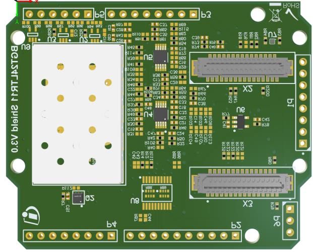
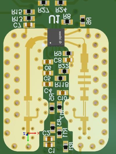
Sense2GoL Pulse (Pulsed Doppler) low-power radar Shield using BGT24LTR11
for motion, speed and direction of movement detection
Hardware description – BGT24LTR11 Shield

4.3 Power supply
The Radar Baseboard XMC4700 is powered via micro-USB connector, external 7 V power supply or LiPo battery.
It also provides the supply for the BGT24LTR11 Shield via the connectors. A LDO (U6) is used on the
BGT24LTR11 Shield to supply all the components. Figure 7 shows the power supply concept used in the system.

 Rshunt

 Connectors b/w Base Board and
 VCC = 3.3 V

 Radar Shield
Micro USB / 5V VCC1 VCC1
External supply / Current sensors IN OUT
LiPo battery C41 LDO C42
 4.7 µF 1 µF
 EN

Figure 7 Block diagram – power supply concept

4.4 EEPROM
The BGT24LTR11 Shield contains an EEPROM (U7) to store data such as a board identifier. The Serial Data (SDA)
is a bi-directional pin that is used to transfer addresses and data into and out of the device. The Serial Clock
(SCL) is an input that is used to synchronize the data from and to the device.
When the Shield is plugged into the Radar Baseboard XMC4700, the sensor’s supplies are initially deactivated.
Only the EEPROM is powered. The MCU reads the content of the EEPROM’s memory to determine which shield
is plugged into the interface. Only when the board has been correctly identified are the sensor’s supplies
activated.

 VCC
 Connectors b/w Radar Baseboard and

 XMC4700

 VCC VSS

 EEPROM
 RF Shield

 I2C_EEPROM.SCL
 SCL SDA

 R83 R84
 USIC

 VCC
 I2C_EEPROM.SDA

Figure 8 EEPROM block diagram

4.5 RF front end
Figure 9 shows the top view of the RF front end. The RF front-end can be shielded with a cover and absorber
material to get the best RF performance. The transmitter and receiver inputs of the BGT24LTR11 are single-
ended. The TX output and RX input are connected over a matching structure, a DC block and a feed-through via
to the antennas on the other side of the board. The isolation between the RX and TX ports is improved by
adding a grounded length of line at the ground pins next to the TX output pin, as shown in Figure 9.

Application Note page 16 of 37 V2.0
 2021-08-13
Sense2GoL Pulse (Pulsed Doppler) low-power radar Shield using BGT24LTR11
for motion, speed and direction of movement detection
Hardware description – BGT24LTR11 Shield

 RX TX

 DC blocks
 Radar front-end
 shielding

 Harmonics
 filter

 Compensation
 structures (stubs)

 BGT24LTR11

Figure 9 RF front-end overview (top)

4.6 BGT24LTR11 – 24 GHz transceiver MMIC
The heart of the sensor module is the highly integrated BGT24LTR11 24 GHz transceiver IC. Figure 10 shows the
detailed block diagram of the MMIC. BGT24LTR11 is a radar MMIC for signal generation and reception,
operating in the 24.000 GHz to 24.250 GHz ISM band. It is based on a 24 GHz fundamental Voltage Controlled
Oscillator (VCO).

Figure 10 Block diagram – BGT24LTR11

A built-in voltage source delivers a VCO PTAT tuning voltage. When connected to the VCO tuning pin it
compensates for the inherent frequency drift of the VCO over-temperature, thus stabilizing the VCO within the
ISM band and eliminating the need for a PLL/microcontroller. The PTAT is also duty cycled and voltage at VCO
tuning pin stabilized via S&H circuitry to further minimize power concumption.
The receiver section uses a Low Noise Amplifier (LNA) in front of a quadrature homodyne down-conversion
mixer in order to provide excellent receiver sensitivity. Derived from the internal VCO signal, a RC Poly-Phase
Filter (PPF) generates quadrature LO signals for the quadrature mixer. I/Q IF outputs are available through
single-ended terminals.

Application Note page 17 of 37 V2.0
 2021-08-13
Sense2GoL Pulse (Pulsed Doppler) low-power radar Shield using BGT24LTR11
for motion, speed and direction of movement detection
Hardware description – BGT24LTR11 Shield

4.7 Antennas
The BGT24LTR11 Shield features a 4 x 1 array antenna for the transceiver and receiver sections. The antenna
has a gain of 10 dBi and a Half-Power Beam Width (HPBW)of 29 x 80 degrees. Figure 11 shows the simulated 2D
and 3D radiation pattern.

 z

 x

 y

Figure 11 2D radiation pattern for array antennas

Application Note page 18 of 37 V2.0
 2021-08-13
Sense2GoL Pulse (Pulsed Doppler) low-power radar Shield using BGT24LTR11
for motion, speed and direction of movement detection
Hardware description – BGT24LTR11 Shield

4.8 Sample and Hold (S&H) circuitry
The BGT24LTR11 Shield has S&H circuitry between the MMIC and the baseband section. The I/Q signals from
the BGT24LTR11 are connected to the inputs of SPST switches. The control signal S&H_EN is generated by the
MCU on the radar baseboard and routed via connectors to the RF shield. When the switch is closed (sample
mode), the hold capacitor (Chold) follows the I/Q analog signal of the BGT and charges to its peak value. When
the switch is opened (hold mode), the Chold holds the sampled voltage. This implementation allows us to turn
the BGT24LTR11 off during the “hold time” and hence save power. The output of the S&H circuitry is amplified
and filtered by the baseband section. It is important to follow the Nyquist criteria for the analog input signal
(I/Q) and the control signal, S&H_EN. The frequency of the control signal should be at least twice the frequency
of the input signal. Figure 12 shows the block diagram of the circuitry and Figure 13 shows the corresponding
signals.

 Sample&Hold I/Q
 I/Q analog signal
 IN OUT output to
 from BGT24LTR11
 baseband section
 SPST Switch
 Chold

 EN
 S&H_EN from
 Radar Baseboard
 XMC4700
 closed: Sample
 S H S H S H
 open: Hold

Figure 12 S&H circuitry

The sample time is a portion of the “pulse width”. The pulse width can vary from 1 to 10 µs. Short pulse widths
reduce the sample time of the MMIC’s output signals, saving more power. However, the time might not be
enough to charge to the peak value, and so reduce the final signal strength at the output.

 pulse width = 5 µs
 fif = 100 Hz

 T
 SAMPLE
 HOLD

 HOLD

Figure 13 S&H circuit signals

Application Note page 19 of 37 V2.0
 2021-08-13
Sense2GoL Pulse (Pulsed Doppler) low-power radar Shield using BGT24LTR11
for motion, speed and direction of movement detection
Hardware description – BGT24LTR11 Shield

The hold capacitor value is also a critical point of the circuit. It is a trade-off between current saving capability,
preserving the S&H voltage and low-pass filter performance. S&H capacitor leakage must be very low.
For the S&H switch, the leakage current performance is also very important. Leakage in the S&H structure will
cause a severe periodic voltage drop of the S&H voltage at sample rate (as shown in Figure 13). This is also
visible as an unwanted interferer frequency at sampling frequency at the output of the baseband circuitry. In
critical cases, it can block the baseband amplifier. The S&H switch used has a very low leakage current and it is
therefore not recommended to change it.
Another S&H switch is added between V_PTAT output and V_TUNE input of the MMIC. This further reduces the
current consumption by allowing duty cycling of the V_PTAT.

4.8.1 Basic considerations on the S&H circuit
During the S&H process, the entire MMIC (BGT24LTR11) is switched on and off periodically (pulsing). Therefore,
the I and Q mixer output from the MMIC will produce short pulses periodically. Each pulse is a discrete, very
short sample of the mixer’s DC bias voltage superimposed by the actual AC Doppler swing. In BGT off-state, the
mixer output becomes zero. The S&H circuit after the mixer output converts a discrete time signal into a
continuous time signal by preserving the entire mixer voltage during the pulse off-time.
Switching on the BGT and the S&H switch, the S&H capacitor shows the same DC voltage as the mixer output,
because the total voltage (DC + AC) is preserved in the S&H capacitor from the previous pulse. Therefore, only
the superimposed AC voltage must be updated without the need to recharge the S&H capacitor for the DC bias
voltage.
The required time for updating the AC voltage depends on the mixer output frequency (Doppler frequency) and
the time constant of the RC LP1 filter formed by the mixer output impedance and the S&H capacitor. For a given
S&H time, the S&H capacitor must be selected to enable an update of the actual S&H voltage.

 Tp Ts
 LP1
 Rise-time of
 Vo after LP1

 RC LP_ BW-3dB = 0.22/tr Hz (start: 20% / end: 80%)
 RC LP_ BW-3dB = 55 kHz
 RC LP_ BW-3dB = 1/(2π*R*C)
 tr = 4 µs (S&H ON time)
 R= (mixer output impedance)
 ➔ C = 5.7 nF (Hold capacitor)

Figure 14 Hold capacitor calculation

The target is to use a RC capacitor with high capacitance although the AC voltage is not fully recharged (20
percent to 80 percent rise-time calc.). A higher capacitor value will reduce noise folding, but leads to a slightly
lower magnitude of the baseband Doppler signal.

Application Note page 20 of 37 V2.0
 2021-08-13
Sense2GoL Pulse (Pulsed Doppler) low-power radar Shield using BGT24LTR11
for motion, speed and direction of movement detection
Hardware description – BGT24LTR11 Shield

4.9 Analog baseband section
The BGT24LTR11 provides both in-phase and quadrature-phase Intermediate Frequency (IF) signals from its
receiver. Depending on the target in front of the radar antennas, the analog output signal from the BGT24LTR11
chipset can be very low in amplitude (µV to mV range). To process these low-amplitude signals it is necessary to
amplify the IF signals.
The BGT24LTR11 Shield offers two stages of signal amplification using low-noise operational amplifiers. As
shown in Figure 15 and Figure 16, the I/Q outputs of the S&H circuit are filtered and amplified in the first gain
stage. The second gain stage consists of a DC block operating as a high-pass filter and a multiple feedback
active filter topology which provides additional gain and bandpass filtering to the output of the first gain stage.
The low-gain and high-gain output signals are low-pass filtered to avoid aliasing. A voltage divider is used to
create the 1.65 V reference voltage.

 PWM5 (S&H_EN)

 EN

 Radar Baseboard XMC4700
 EN IFI_LG
 LP anti-aliasing filter
 IFI OUT
 IN IN
 OUT

 Connector to
 Chold IFI_HG
 DC block Multiple feedback LPF
 BGT24LTR11 EN
 EN IFQ_LG
 LP anti-aliasing filter
 IFQ OUT
 IN IN
 OUT
 IFQ_HG
 Chold DC block Multiple feedback LPF

 Base band section

Figure 15 Baseband amplifier chain – block diagram

 Non-inverting BPF
 DC block/HPF
 LP anti-aliasing filter
 Multiple feedback LPF

Figure 16 Baseband amplifier chain – schematics

Application Note page 21 of 37 V2.0
 2021-08-13
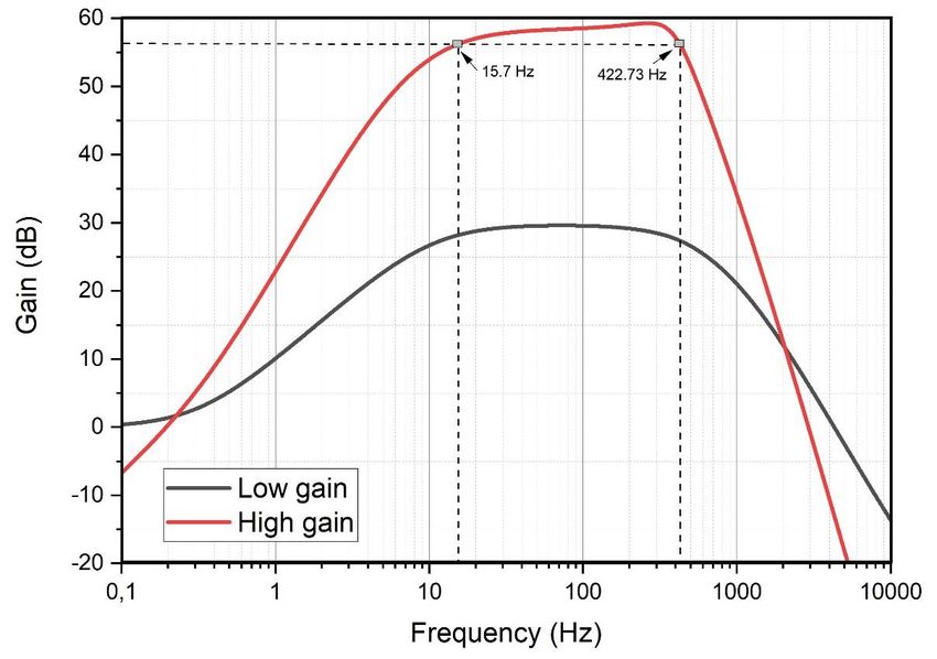
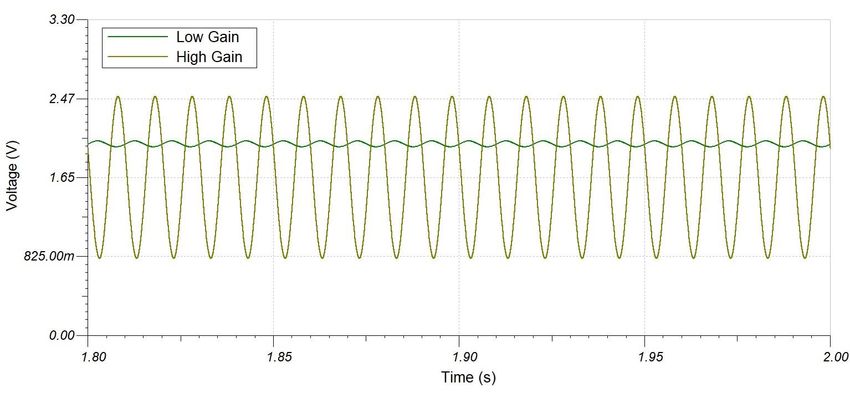
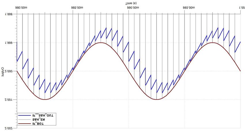
Sense2GoL Pulse (Pulsed Doppler) low-power radar Shield using BGT24LTR11
for motion, speed and direction of movement detection
Hardware description – BGT24LTR11 Shield

Figure 17 shows exemplary IF low-gain and high-gain signals. The offset of the low-gain signal equals the static
offset of the BGT output signals. Due to the DC block at the beginning of the second stage, the offset of the
high-gain signal matches the reference voltage of 1.65 V.

Figure 17 IF low-gain and high-gain signals for an input of 100 Hz, 1 mV input signal

As shown in Figure 18, the first gain stage provides a gain of 29.62 dB (low-gain stage) and both the stages
together provide a gain of 59.31 dB (high-gain stage). The 3dB cutoff frequencies are also marked in this figure.

Figure 18 Baseband frequency response for low-gain and high-gain stages

Figure 18 shows the frequency response of the low- and high-gain stages. The BGT24LTR11 Shield allows the
user to select either the low-gain (first stage only) or high-gain (first stage + second stage) mode depending on
Application Note page 22 of 37 V2.0
 2021-08-13
Sense2GoL Pulse (Pulsed Doppler) low-power radar Shield using BGT24LTR11
for motion, speed and direction of movement detection
Hardware description – BGT24LTR11 Shield

the target RCS and distance to be detected. The low-gain output is referenced to the individual mixer output
bias voltage (1.6 to 2.0 V), and the high-gain stage is AC coupled and referenced to VCC/2 = 1.65 V.
Table 2 lists the MCU pins (on the Radar Baseboard XMC4700) associated with each of the gain stages. Use the
graphical pin select tool in the DAVE™ software to select the appropriate pins for signal processing.

 Table 2 Baseband amplifiers to MCU pin connections
 XMC4700 – port pin Pin label Pin function
 P14.6 (VADC.G0CH6) IF.I1 IFI – high gain
 P14.7 (VADC.G0CH7) / P14.3 (VADC.G1CH3) IF.Q1 IFQ – high gain
 P14.14 (VADC.G1CH6) / P15.3 (VADC.G2CH3) IF.I2 IFI – low gain
 P14.15 (VADC.G1CH7) / P15.9 (VADC.G3CH1) IF.Q2 IFQ – low gain

The gain and bandwidth of the IF stages are fixed and can be manually configured by the user by changing the
resistor and capacitor values specified in Table 3. In addition to Table 3, AC coupling by C27 and the input
impedance of the I_multiple feedback filter (MFB LP by the second stage) form the second high-pass for the I-
channel. For the Q-channel contributors are C29 and the input impedance (Q_MFB low-pass).

Table 3 Baseband amplifier components and settings
IF stage Designator Gain Configurable components – Configurable components
 I section – Q section

Stage 1 U5A 29.66 dB C16, R33, C17, R36 C37, R65, C35, R61
(low gain)
Stage 1 + Stage 2 U5A + U4A 59.28 dB All components as All components as
(high gain) mentioned for Stage 1 + mentioned for Stage 1 +
 R49, R50, R32, C23, C24 R55, R56, C34, R63, C33

4.9.1 Baseband amplifier settings for Doppler radar
The baseband section should be configured accordingly to provide sufficient gain at these frequencies. The cut-
off frequencies of the baseband section are 15 to 420 Hz.
The Doppler frequency is calculated using the following formula:
 2
 ( ) =

 Where = speed of the target (m/s)
 = wavelength (m)

Table 4 shows the calculated Doppler frequency values for different target speeds for the 24 GHz radar module.

Table 4 Doppler shift frequencies for different speeds using 24 GHz radar
Speed (km/h) 0.5 1 2 4 6 8 10 12
Doppler shift (Hz) 22 44 89 178 268 357 446 536

Application Note page 23 of 37 V2.0
 2021-08-13
Sense2GoL Pulse (Pulsed Doppler) low-power radar Shield using BGT24LTR11
for motion, speed and direction of movement detection
System configuration and parameters

5 System configuration and parameters
Figure 19 shows the configuration of a frame. Each frame is a series of pulses, followed by a frame off-time.
 Frame time
 Frame ON time Frame OFF time
 Pulse width

 2 Nskip 1 2 3 4 Nsamples
Figure 19 Frame structure and terminology

The steps below explain the design and calculations for the system:

 = 2 × × cos( ) ×

 1
 =

1. Select ( / ) to determine maximum Doppler frequency:

 2 ×
 = =

2. Select ( / ) to determine minimum Doppler frequency :

 2 ×
 = =

These and values are the cut-off frequencies for the baseband section.

3. Determine the minimum sampling frequency and Pulse Repetition Time ( ).
The required sampling frequency ( ) depends on the maximum targeted baseband frequency and on
the required over-sampling (minimum factor 2) to get more headroom for the real anti-aliasing filter.

 ≥ 2 ×

 1
 =

4. Determine the minimum number of samples per frame ( ):

 ≥ , ℎ 2

Application Note page 24 of 37 V2.0
 2021-08-13
Sense2GoL Pulse (Pulsed Doppler) low-power radar Shield using BGT24LTR11
for motion, speed and direction of movement detection
System configuration and parameters

5. Determine the minimum :
Sample skip count ( ) is the number of samples to be skipped at the beginning of each frame to get rid of
the DC offset in the I/Q signals generated in the pulse interval time. These samples are completely disregarded
in the signal processing chain. Therefore, total number of samples per frame ( ) are:

 = +

 = = ×

6. Select frame time or update rate:
 1
 = ≥

Table 5 System parameters, symbols and units
Symbol Parameter Unit
 Wavelength mm
 Transmit frequency GHz
 Speed of light m/s
 Maximum speed to be detected m/s
 Minimum speed to be detected m/s
 Max. IF freq. (max. Doppler frequency) Hz
 Min. IF freq. (min. Doppler frequency) Hz
 Sampling frequency Hz
 Pulse repetition time µs
 No. of samples per frame –
 No. of samples to be skipped per frame –
 Total number of samples per frame -
 Duration in which pulses are generated ms
 Total frame time ms
 No. of frames per second Hz
 ℎ Width of each pulse µs

Application Note page 25 of 37 V2.0
 2021-08-13
Sense2GoL Pulse (Pulsed Doppler) low-power radar Shield using BGT24LTR11
for motion, speed and direction of movement detection
System configuration and parameters

 1 BGT turns ON

 2 TX of BGT turns ON

 3 S&H switch closes (sample mode)

 S&H switch opens (hold mode),
 4
 TX of BGT turns OFF

 5 ADC triggers

 6 BGT turns OFF

 a b c d e

 Pulse Width

Figure 20 Pulse timing configuration

Figure 20 shows the pulse timing configuration and the steps in which the actions occur. The timings a, b, d and
e remain fixed. If the pulse width is increased or decreased, the S&H time (c) is increased or decreased, which in
turn affects the on-time of the BGT24LTR11 MMIC. For more timing information, refer to the Software User
Manual.

Application Note page 26 of 37 V2.0
 2021-08-13
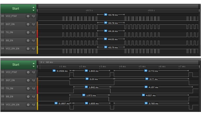
Sense2GoL Pulse (Pulsed Doppler) low-power radar Shield using BGT24LTR11
for motion, speed and direction of movement detection
Power consumption analysis

6 Power consumption analysis
The BGT24LTR11 Shield is designed for low-power consumption.
• The MMIC is turned on only during the ‘pulse width of MMIC ( )’ duration and remains off for the
 remaining time in the frame.
• The PTAT of the MMIC is turned on 1 ms before the start of the frame .This is done to make sure the V_PTAT
 voltage settles to keep the VCO at the center frequency before the pulses start. It is a key step to avoid out-
 of-band emissions. The PTAT of the MMIC consumes extra current when on. Therefore, for each pulse in the
 frame, the PTAT is duty cycled as per the ‘pulse width of PTAT ( )’.
• The baseband section consists of the two stages of operational amplifiers and the voltage divider to
 generate 1.65 V. In order to save current consumption, the baseband section is also duty cycled and turned
 on 20 ms before the first sample of a frame and turned off shortly after the last sample of the frame.
As shown in Table 6, the major contributors to the power consumption are BGT24LTR11 and PTAT. The overall
power consumption can be optimized by varying , pulse width and frame time.

Table 6 Power consumption overview
 Component Current consumption (mA) On-time
 BGT24LTR11 (MMIC) 45 ×
 PTAT 1.5 ( × ) + 1
 Baseband section 0.335 ( − 1) × + 22
 (op-amps and voltage divider)

In default settings, (frame time: 150 ms, : 5 µs, : 20 µs, : 128, : 40), the current
consumption is 0.49 mA. Figure 21 shows the logic analyzer plot for the default settings.

Figure 21 On/Off timing diagram – Saleae Logic analyzer plot

Application Note page 27 of 37 V2.0
 2021-08-13
Sense2GoL Pulse (Pulsed Doppler) low-power radar Shield using BGT24LTR11
for motion, speed and direction of movement detection
External pin header connectors

7 External pin header connectors
The BGT24LTR11 Shield has the provision to connect multiple headers on the edge of the board. Figure 22
shows the pin headers on the PCB, and Table 7, Table 8, Table 9, Table 10 and Table 11 describe the pins.

 8 7 6 5 4 3 2 1 10 9 8 7 6 5 4 3 2 1
 3

 2

 1

 8

 7

 6

 5

 4

 3

 2

 1

 6 5 4 3 2 1 8 7 6 5 4 3 2 1

Figure 22 External headers – P1, P2, P3, P4,P5 and P6

Table 7 External headers (P1) – pin description
 Pin no. Signal name Pin description
 1 TP_VCC_PTAT Control signal for VCC_PTAT pin of MMIC
 2 TP_TX_EN Control signal for TX_ON pin of MMIC
 3 TP_VCC_BGT_EN Control signal for Q1 PMOS switch to turn MMIC on/off
 4 GND Ground
 5 IFI_HG Second baseband amplifier stage output for IFI signal
 6 IFQ_HG Second baseband amplifier stage output for IFQ signal
 7 CCU80_Out.Slice2 Control signal for S&H (SPST) switches
 8 TP_VCC_DIV_EN Control signal for VCC_DIV pin of MMIC

Application Note page 28 of 37 V2.0
 2021-08-13
Sense2GoL Pulse (Pulsed Doppler) low-power radar Shield using BGT24LTR11
for motion, speed and direction of movement detection
External pin header connectors

Table 8 External headers (P2) – pin description
 Pin no. Signal name Pin description
 1 ARD_SCL (I2C_EEPROM.SCL) serial clock input of the EEPROM
 2 ARD_SDA (I2C_EEPROM.SDA) serial data pin of the EEPROM
 3 3V3 3.3 V power supply to Arduino
 4 Ground Ground
 7 ARD_PWM_5 Control signal to turn on/off the 1st stage of baseband amplification
 8 ARD_PWM_4 Control signal for V_PTAT
 9 ARD_PWM_3 Control signal for IFI and IFQ

Table 9 External headers (P3) – pin description
 Pin no. Signal name Pin description
 Voltage reference at which the external board interfacing with the Radar
 2 IOREF
 Baseboard XMC4700 is operating
 4 3V3_digital 3.3 V power supply to Arduino
 5 5V 5 V power supply to Arduino
 6 Ground Ground
 7 Ground Ground

Table 10 External headers (P4) – pin description
 Pin no. Signal name Pin description
 2 ARD_PWM_2 VCC_PTAT_On control signal to turn PTAT on/off
 3 ARD_PWM_1 TX_ON control signal for turning the TX of BGT24LTR11 on/off
 5 ARD_PWM_0 VCC_ON control signal for turning the BGT24LTR11 on/off (via Q1 PMOS)

Table 11 External headers (P5) – pin description
 Pin no. Signal name Pin description
 IFI_HG signal from the second baseband stage. Place R94 (0 Ω) and remove
 1 ARD_ADC_0/IFI_LG
 R93 to see IFI_LG signal from the first baseband stage.
 IFQ_HG signal from the second baseband stage. Place R96 (0 Ω) and
 2 ARD_ADC_1/IFQ_LG
 remove R95 to see IFQ_LG signal from the first baseband stage.
 3 ARD_ADC_2 VTUNE_St_FMCW signal for stepped FMCW implementation
 4 ARD_ADC_3 DIVOUT_St_FMCW signal for stepped FMCW implementation
 5 ARD_ADC_4 V_PTAT output from BGT24LTR11
 6 ARD_ADC_5

Table 12 External headers (P6) – pin description
 Pin no. Signal name Pin description
 CCU80_Out.Slice3 Control signal for V_PTAT
 1
 (V_PTAT_S&H_EN)
 2 BB1_EN Control signal for first baseband stage.
 3 V_DAC_1 Control signal for V_DAC

Application Note page 29 of 37 V2.0
 2021-08-13
Sense2GoL Pulse (Pulsed Doppler) low-power radar Shield using BGT24LTR11
for motion, speed and direction of movement detection
External pin header connectors

Notes:

1. Pins 5, 6 of header P2 are not connected to any signal.
2. Pins 1,3, 8 of header P3 are not connected to any signal.
3. Pins 1, 4, 6, 7, 8 of header P4 are not connected to any signal.
4. Pin 6 of header P5 is not connected to any signal.
The pin headers enhance the functionality of the module significantly. They enable probing the analog outputs
of the sensor module and also probing various other signals provided to the IC. In principle, the accessibility of
several pins on the radar IC and the IF signals available via the external pin headers enable interfacing the
module with an external signal processor.

Application Note page 30 of 37 V2.0
 2021-08-13
Sense2GoL Pulse (Pulsed Doppler) low-power radar Shield using BGT24LTR11
for motion, speed and direction of movement detection
Use cases and applications

8 Use cases and applications
8.1 Human walking detection
The system is capable of detecting a single target walking in front of the radar within a distance of 15 m. This
can address various indoor and outdoor applications, including:

 • smart door openers based on direction of movement (Figure 24)

 • security camera activation when a human is approaching
 • smart device activation when a human is approaching

 • smart toilet automatic flushing when a human is departing.

 Approaching Departing

 Radar Radar

 Target Target

Figure 23 Human walking – use-case visualization

 No target Stationary target Target departing Target passing by Target approaching

 closed closed closed closed open

 Radar system

Figure 24 Smart door opener – use-case visualization

Since the sensor can determine the direction of movement, it reduces the false alarms caused by regular
motion triggered sensors (like PIR). Moreover, it can be hidden in the end application as it senses through non-
metallic materials.

Table 13 Recommended settings for human motion detection
Parameter Value Comment
No. of samples per frame ≥ 128 Power of 2
Sampling frequency ≥ 1000 Hz Based on max speed
Pulse width ≥ 4 µs -
Frame rate ≥ 2 Hz i.e., Frame time ≤ 500 ms
Application Note page 31 of 37 V2.0
 2021-08-13
Sense2GoL Pulse (Pulsed Doppler) low-power radar Shield using BGT24LTR11
for motion, speed and direction of movement detection
Measurement results

9 Measurement results
9.1 Velocity detection
Speed measurements were performed using a Doppler simulator and the Sense2GoL Pulse system for both
approaching and departing configurations. The results can be seen in Figure 25.

Figure 25 Speed measurements (Doppler simulator vs radar)

The system is able to detect speeds between 0.1 and 3 m/s for the settings mentioned. For human targets, the
module is able to detect movement up to 18 m range.

9.2 Human movement detection
The system is designed for use cases like presence detection, motion and direction of movement detection for
a single human target. It enables detection of a human walking within a distance of 20 m in an indoor or
outdoor environment. Figure 26 shows the detection area for a human target.

Figure 26 Motion detection area for a human target area

Application Note page 32 of 37 V2.0
 2021-08-13
Sense2GoL Pulse (Pulsed Doppler) low-power radar Shield using BGT24LTR11
for motion, speed and direction of movement detection
Frequency band and regulations

10 Frequency band and regulations
10.1 24 GHz regulations
Infineon’s BGT24LTR11 radar sensor operates in the globally available 24 GHz bands. There is an Industrial,
Scientific and Medical (ISM) band from 24 to 24.25 GHz. However, each country may have deviating regulations
in terms of occupied bandwidth, maximum allowed radiated power, conducted power, spurious emissions, etc.
Therefore, it is highly recommended checking the local regulations before designing an end product.

10.2 Regulations in Europe
In Europe, the European Telecommunications Standards Institute (ETSI) defines the regulations. For more
details on the ETSI standards, please refer to the document EN 300 440 V2.2.1. Please note that some countries
do not follow harmonized European standards. Thus, it is recommended to check national regulations for
operation within specific regions and monitor regulatory changes.

10.3 Regulations in the United States of America
In the USA, the Federal Communications Commission (FCC) defines standards and regulations. The ISM band
covers 24 to 24.25 GHz and one can operate field disturbance sensors anywhere within this band within allowed
power limits for certain applications. For details, please refer to FCC section number 15.245 or 15.249.

Application Note page 33 of 37 V2.0
 2021-08-13
You can also read