Axial piston variable motor - A36VM - Bosch Rexroth
←
→
Page content transcription
If your browser does not render page correctly, please read the page content below
Instruction manual

Axial piston
variable motor
A36VM

            RE 91650-01-B/2021-07-19, replaces: 10.2017 EN
© Bosch Rexroth AG 2021. All rights reserved, also regarding any disposal, exploitation, reproduction, editing, distribution, as well as in the event of applications for industrial property rights. The data specified within only serves to describe the product. No statements concerning a certain condition or suitability for a certain application can be derived from our information. The information given does not release the user from the obligation of own judgment and verification. It must be remembered that our products are subject to a natural process of wear and aging. The cover shows an example application. The product delivered may differ from the image on the cover. The original operating instructions were created in German.
Contents | A36VM                   3/54

Contents
1         About this documentation������������������������������������������������������������������������ 5
1.1       Validity of the documentation���������������������������������������������������������������������� 5
1.2       Required and supplementary documentation����������������������������������������������� 5
1.3       Representation of information���������������������������������������������������������������������� 5
1.3.1 Safety instructions��������������������������������������������������������������������������������������� 6
1.3.2 Symbols������������������������������������������������������������������������������������������������������� 7
1.3.3 Designations������������������������������������������������������������������������������������������������ 7
1.3.4 Abbreviations����������������������������������������������������������������������������������������������� 7
2         Safety instructions����������������������������������������������������������������������������������� 8
2.1       About this chapter���������������������������������������������������������������������������������������� 8
2.2       Intended use������������������������������������������������������������������������������������������������ 8
2.3       Improper use������������������������������������������������������������������������������������������������ 8
2.4       Personnel qualifications������������������������������������������������������������������������������� 9
2.5       General safety instructions������������������������������������������������������������������������ 10
2.6       Product-specific safety instructions����������������������������������������������������������� 11
2.7       Personal protective equipment������������������������������������������������������������������ 14
3         General instructions on property damage and product damage�������������� 15
4         Scope of delivery����������������������������������������������������������������������������������� 18
5         About this product��������������������������������������������������������������������������������� 19
5.1       Performance description���������������������������������������������������������������������������� 19
5.2       Product description����������������������������������������������������������������������������������� 19
5.2.1 Axial piston unit layout������������������������������������������������������������������������������� 19
5.2.2     Functional description������������������������������������������������������������������������������� 20
5.3       Product identification��������������������������������������������������������������������������������� 21
6         Transport and storage���������������������������������������������������������������������������� 22
6.1       Transporting the axial piston unit��������������������������������������������������������������� 22
6.1.1 Transport by hand�������������������������������������������������������������������������������������� 22
6.1.2 Transport with lifting devices��������������������������������������������������������������������� 23
6.2       Storing the axial piston unit����������������������������������������������������������������������� 24
7         Installation�������������������������������������������������������������������������������������������� 26
7.1       Unpacking�������������������������������������������������������������������������������������������������� 26
7.2       Installation conditions�������������������������������������������������������������������������������� 26
7.3       Installation position����������������������������������������������������������������������������������� 28
7.3.1 Below-reservoir installation (standard)������������������������������������������������������ 28
7.3.2     Above-reservoir installation������������������������������������������������������������������������ 29
7.4       Installing the axial piston unit�������������������������������������������������������������������� 30
7.4.1 Preparation������������������������������������������������������������������������������������������������ 30
7.4.2     Dimensions������������������������������������������������������������������������������������������������ 30
7.4.3     General instructions����������������������������������������������������������������������������������� 30
7.4.4     Installation with a coupling������������������������������������������������������������������������ 31
7.4.5     Installation on a gearbox���������������������������������������������������������������������������� 32
7.4.6     Completion of assembly����������������������������������������������������������������������������� 32
7.4.7     Hydraulically connecting the axial piston unit�������������������������������������������� 33
7.4.8     Electrically connecting the axial piston unit����������������������������������������������� 37
7.5       Performing flushing cycle��������������������������������������������������������������������������� 37

                                                             RE 91650-01-B/2021-07-19, Bosch Rexroth AG
4/54 A36VM | Contents
8 Commissioning��������������������������������������������������������������������������������������� 38
8.1 Initial commissioning��������������������������������������������������������������������������������� 38
8.1.1 Filling the axial piston unit������������������������������������������������������������������������� 38
8.1.2 Testing the hydraulic fluid supply��������������������������������������������������������������� 39
8.1.3 Performing a functional test����������������������������������������������������������������������� 40
8.2 Running-in phase��������������������������������������������������������������������������������������� 40
8.3 Recommissioning after standstill��������������������������������������������������������������� 41
9 Operation����������������������������������������������������������������������������������������������� 42
10 Maintenance and repair�������������������������������������������������������������������������� 43
10.1 Cleaning and care�������������������������������������������������������������������������������������� 43
10.2 Inspection�������������������������������������������������������������������������������������������������� 43
10.3 Maintenance����������������������������������������������������������������������������������������������� 44
10.4 Repair�������������������������������������������������������������������������������������������������������� 44
10.5 Spare parts������������������������������������������������������������������������������������������������ 45
11 Removal and replacement���������������������������������������������������������������������� 46
11.1 Required tools�������������������������������������������������������������������������������������������� 46
11.2 Preparing for removal��������������������������������������������������������������������������������� 46
11.3 Performing the removal������������������������������������������������������������������������������ 46
11.4 Preparing the components for storage or further use��������������������������������� 46
12 Disposal������������������������������������������������������������������������������������������������� 47
13 Extension and conversion����������������������������������������������������������������������� 48
14 Troubleshooting������������������������������������������������������������������������������������� 49
14.1 How to proceed for troubleshooting����������������������������������������������������������� 49
14.2 Malfunction table��������������������������������������������������������������������������������������� 50
15 Technical data���������������������������������������������������������������������������������������� 52
16 Alphabetical index��������������������������������������������������������������������������������� 53
Bosch Rexroth AG, RE 91650-01-B/2021-07-19About this documentation | A36VM 5/54
1 About this documentation
1.1 Validity of the documentation
This documentation is valid for the following products:
• Axial piston variable motor A36VM
This documentation is intended for machine/system manufacturers, assemblers and
service engineers.
This documentation contains important information on the safe and proper
transport, assembly, commissioning, operation, maintenance, removal and simple
troubleshooting of the axial piston unit.
▶ Read this documentation completely, in particular chapter 2 "Safety instructions"
on page 8 and chapter 3 "General instructions on property damage and
product damage" on page 15 before you start work with the axial piston unit.
1.2 Required and supplementary documentation
▶ Only commission the axial piston unit if the documentation marked with the
book symbol is available to you and you have understood and observed it.
Table 1: Required and supplementary documentation
Title Document number Document type
Order confirmation – Order confirmation
Contains the order-related technical data for your axial piston variable motor A36VM.
Installation drawing Please request the Installation drawing
Contains the outer dimensions, all connections and the hydraulic circuit diagram installation drawing
for your axial piston variable motor A36VM. from your contact
at Bosch Rexroth.
Axial piston variable motor A36VM 91650 Data sheet
Contains the permissible technical data, ports, main dimensions and circuit
diagrams of standard versions.
Hydraulic fluids based on mineral oils and related hydrocarbons 90220 Data sheet
Describes the requirements on a mineral oil-based hydraulic fluid and related
hydrocarbons for operation with Rexroth hydraulic components and assists you in
selecting a hydraulic fluid for your hydraulic system.
Bosch Rexroth Fluid Rating List for Rexroth hydraulic components 90245 Data sheet
(pumps and motors)
Contains the hydraulic fluids positively evaluated by Bosch Rexroth.
Information on the application of hydrostatic drives at low temperatures 90300-03-B Manual
Contains additional information on the application of Rexroth axial piston units
at low temperatures.
Storage and preservation of axial piston units 90312 Data sheet
Contains additional information on storage and preservation.
1.3 Representation of information
Uniform safety instructions, symbols, terms and abbreviations are used throughout
this documentation to ensure safe and proper use of the product. For clarification,
they are explained in the sections below.
RE 91650-01-B/2021-07-19, Bosch Rexroth AG6/54 A36VM | About this documentation
1.3.1 Safety instructions
This documentation contains safety instructions in chapter 2.6 "Product-specific
safety instructions" on page 11 and in chapter 3 "General instructions on property
damage and product damage" on page 15, as well as before a sequence of actions
or an instruction for action involving a risk of personal injury and property damage.
Always follow the measures for danger prevention associated with the use of
this product.
Safety instructions are set out as follows:
SIGNAL WORD
Type and source of danger!
Consequences of noncompliance
▶ Danger prevention measures
• Warning sign: draws attention to the danger
• Signal word: identifies the degree of the danger
• Type and source of danger: indicates the type and source of the danger
• Consequences: describes what occurs if safety instructions are disregarded
• Precautions: states how the danger can be avoided
Table 2: Hazard classes as defined in ANSI Z535.6
Warning sign, signal word Meaning
Identifies a dangerous situation that will result in death or
DANGER serious injury if it is not avoided.
Identifies a dangerous situation that may result in death or
WARNING serious injury if it is not avoided.
Identifies a dangerous situation that may result in minor to
CAUTION moderate injury if it is not avoided.
Property damage: The product or surrounding area may be
NOTICE damaged.
Bosch Rexroth AG, RE 91650-01-B/2021-07-19About this documentation | A36VM 7/54
1.3.2 Symbols
The following symbols indicate notices that are not safety-relevant but increase
understanding of the documentation.
Table 3: Meaning of symbols
Symbol Meaning
If this information is disregarded, the product cannot be used and/or
operated to its full extent.
▶ Single, independent action
1. Numbered instruction:
2. The numbers indicate that the actions must be completed in order.
3.
1.3.3 Designations
This documentation uses the following designations:
Table 4: Designations
Designation Meaning
A36VM Axial piston variable motor, closed circuit
Threaded plug Metal screw, pressure-resistant
Protective plug Made out of plastic, not pressure-resistant, only for transportation
As a generic term for the "axial piston variable motor A36VM", the designation
"axial piston unit" is used in the following.
1.3.4 Abbreviations
This documentation uses the following abbreviations:
Table 5: Abbreviations
Abbreviation Meaning
ANSI American National Standards Institute is an organization that coordinates
the development of voluntary standards in the United States
ATEX EC directive on explosion protection (Atmosphère explosible)
DIN Deutsches Institut für Normung (German Institute for Standardization)
EP Proportional control, electric
HA Automatic control, high pressure-related
ISO International Organization for Standardization
JIS Japan Industrial Standard
RE Rexroth document in the English language
VDI 2230 Guideline for the systematic calculation of heavy-duty
threaded connections and cylindrical screw joints from the VDI
(Verein Deutscher Ingenieure - Association of German Engineers)
RE 91650-01-B/2021-07-19, Bosch Rexroth AG8/54 A36VM | Safety instructions
2 Safety instructions
2.1 About this chapter
The axial piston unit has been manufactured to generally accepted engineering
standards. There is still, however, a risk of personal injury or property damage
if this chapter and the safety instructions in this documentation are not observed.
▶ Read this documentation completely and thoroughly before working with the
axial piston unit.
▶ Keep this documentation in a location where it is accessible to all users at
all times.
▶ Always include the required documentation when you pass the axial piston unit
on to third parties.
2.2 Intended use
Axial piston units are hydraulic components, meaning that in their application area
they are classified neither as complete nor as partly completed machinery in the
sense of the EC Machinery Directive 2006/42/EC. The component is exclusively
intended to form partly completed machinery or complete machinery together with
other components. The component should only be commissioned after it has been
installed in the machine/system for which it is intended, and the safety of the entire
system has been established in accordance with the Machinery Directive.
This product is intended for the following use:
The axial piston unit is only approved as a hydraulic motor in hydrostatic drives
in the closed circuit.
▶ Observe the technical data, the application and operating conditions and
the performance limits as specified in the data sheet 91650 and in the order
confirmation. Information about approved hydraulic fluids can be found in
data sheet 91650.
The axial piston unit is only intended for commercial use and not for private use.
Intended use includes having fully read and understood this documentation,
especially chapter 2 "Safety instructions" on page 8.
2.3 Improper use
Any use other than that described as intended use is considered improper.
Bosch Rexroth AG is not liable for damage resulting from improper use.
The user is solely responsible for any risks arising from improper use.
The following foreseeable forms of faulty usage are also considered improper
(this list is not exhaustive):
• Use outside the operating parameters approved in the data sheet and in the order
confirmation (unless specifically approved by the customer)
• Use of non-approved fluids, e.g. water or polyurethane components
• Changes to factory settings by unauthorized persons.
Bosch Rexroth AG, RE 91650-01-B/2021-07-19Safety instructions | A36VM 9/54
• Use of assembled parts (e.g. control unit, valves) not in combination with the
specified Rexroth components
• Use of the axial piston unit with assembled parts under water at a depth of
more than 10 meters without the necessary additional measures, e.g. pressure
equalization. Units with electrical components (e.g. sensors) must not get
into contact with water, depending on the IP protection class. Observe the
IP protection class in the data sheet91650.
• Use of the axial piston unit under a continuous pressure differential between
housing and ambient pressure greater than 2 bar, with the ambient pressure always
lower than the case pressure. Momentary (t < 0.1 s) pressure peaks of up to 10 bar
are allowed. Beyond this, the maximum permissible case pressure specified in the
data sheet should not be exceeded.
• Application of the axial piston unit in explosive environments unless the component
or machine/system has been certified as compliant with the ATEX Directive
2014/34/EU
• Use of the axial piston unit in a corrosive atmosphere
• Use of the axial piston unit in aircraft or spacecraft
2.4 Personnel qualifications
The activities described in this documentation require a basic understanding of
mechanics, electricity and hydraulics, as well as familiarity with associated technical
terms. For transporting and handling the product, knowledge regarding the use
of lifting devices and lifting accessories is required. In order to ensure safe use,
these activities should only be performed by skilled personnel or an instructed
person under the direction and supervision of skilled personnel.
Skilled personnel refers to persons who possess the professional training,
knowledge and experience, as well as the understanding of the regulations relevant
to the work to be done that are necessary to recognize possible dangers and take
the appropriate safety measures. Skilled personnel must follow the rules relevant
to their field and have the necessary hydraulic expert knowledge.
Hydraulic expert knowledge includes:
• Being able to read and fully understand hydraulic circuit diagrams
• In particular, fully understanding the relationships with regard to safety devices
• Knowledge regarding the function and interaction of hydraulic components.
Bosch Rexroth offers you measures supporting training in specific areas.
You can find an overview of the training contents on the Internet at:
www.boschrexroth.com/training.
RE 91650-01-B/2021-07-19, Bosch Rexroth AG10/54 A36VM | Safety instructions
2.5 General safety instructions
• Observe the country-specific accident prevention and environmental protection
regulations.
• Observe the safety regulations of the country in which the product is
used/operated.
• Use Rexroth products only when they are in good working order.
• Observe all notices on the product.
• Do not assemble, operate, remove or maintain Rexroth products if under the
influence of alcohol, drugs or medication that may affect your reaction time.
• Only use genuine Rexroth accessories and spare parts to ensure there is no hazard
to persons from unsuitable spare parts.
• Observe the technical data and ambient conditions specified in the product
documentation.
• If unsuitable products are installed or used in safety-relevant applications,
unexpected operating conditions may occur in the application, which could result
in personal injury or property damage. For this reason, only use the product in
safety-relevant applications if this use is expressly indicated and approved in the
product documentation, e. g. in explosion protection areas or in safety-related
parts of a control system (functional safety).
• Only commission the product if it has been determined that the end product
(e.g. machinery/system) in which the Rexroth products are installed complies
with the country-specific provisions, safety regulations and standards for the
application.
• Use tools appropriate for the work being performed and wear appropriate
protective clothing to prevent punctures and cuts (e.g. when removing protective
covers, disassembly).
• There is a risk of entanglement when operating the axial piston unit with a bare
shaft end. Check whether or not your machine requires additional safety measures
for your application. If necessary, make sure these are appropriately implemented.
• Depending on the type of control used, electromagnetic effects can be produced
when using solenoids. Applying a direct voltage signal (DC) to solenoids does not
create electromagnetic interference (EMI) nor is the solenoid affected by EMI.
Potential electromagnetic interference (EMI) exists if the solenoid is energized
with a modulated direct current (e.g. PWM signal). The machine manufacturer
should conduct appropriate tests and take appropriate measures to ensure
that other components or operators (e.g. with a pacemaker) are not affected by
this potentiality.
Bosch Rexroth AG, RE 91650-01-B/2021-07-19Safety instructions | A36VM 11/54
2.6 Product-specific safety instructions
The following safety instructions apply to chapters 6 to 14.
WARNING
Danger from excessive pressure!
Risk of death or injury, or property damage!
Improperly changing the factory pressure settings can result in a pressure increase
beyond the permissible maximum pressure.
Operating the unit above the maximum permissible pressure can cause
components to burst and hydraulic fluid to escape under high pressure.
▶ Changes to the factory settings may only be made by Bosch Rexroth specialists.
▶ In addition, a pressure relief valve is required in the hydraulic system as back-up.
If the axial piston unit is equipped with a pressure cut-off and/or pressure
controller, this is not an adequate safeguard against pressure overload.
Danger due to suspended loads!
Risk of death or injury, or property damage!
Improper transportation may cause the axial piston unit to fall down and lead to
injury, e.g. crushing or fracture, or damage to the product.
▶ Make sure that the load bearing capacity of the lifting device is sufficient to
safely bear the weight of the axial piston unit.
▶ Never step or grip under suspended loads.
▶ Ensure a stable transport position.
▶ Use your personal protective equipment (e.g. safety goggles, safety gloves,
suitable working clothes, safety shoes).
▶ Use suitable lifting devices for transport.
▶ Observe the prescribed position of the lifting strap.
▶ Observe the national laws and regulations on occupational health and safety,
and transportation.
System/machine under pressure!
Risk of death or serious injury when working on unsecured machines/systems!
Property damage!
▶ Switch off the relevant machine/system part and secure it against reactivation
according to the parameters by the machine/system manufacturer.
▶ Ensure that all relevant components of the hydraulic system are depressurized.
For this purpose, observe the parameters indicated by the machine/system
manufacturer.
▶ Please note that the hydraulic system might still be pressurized even after
separation from the actual pressure supply.
▶ Do not disconnect any line connections, ports or components as long as the
hydraulic system is under pressure.
RE 91650-01-B/2021-07-19, Bosch Rexroth AG12/54 A36VM | Safety instructions
WARNING
Escaping hydraulic fluid mist!
Risk of explosion and fire hazard, health hazard, risk of environmental pollution!
▶ Depressurize the relevant machine/system component and repair the leak.
▶ Only perform welding work when the machine/system is depressurized.
▶ Keep open flames and ignition sources away from the axial piston unit.
▶ If axial piston units are located in the vicinity of ignition sources or powerful
thermal radiators, a shield must be erected to ensure any escaping hydraulic
fluid cannot be ignited, and to protect hose lines from premature aging.
Escaping hydraulic fluid due to leakage of machine/system components!
Risk of burning and risk of injury due to escaping hydraulic fluid jet!
In case of leakage at the axial piston unit, high-pressure fluid jets may escape.
▶ Depressurize the relevant machine/system component and repair the leak.
▶ Never attempt to block or seal the leak or hydraulic fluid jet with a cloth.
Hydraulic fluid will explode when making contact with water!
Explosion and fire hazard!
▶ Do not bring hot hydraulic fluids in contact with water.
Electrical voltage!
Danger to life or risk of injury due to electric shock or property damage!
▶ Always diskonnect the voltage supply to the relevant machine/system part
before assembling the product and/or connecting or diskonnecting the
connector. Protect the machine/system against being re-energized.
Overloading of the axial piston motor!
Risk of injury or property damage!
When using the axial piston motor in winch drives it may, when extremely
overloaded (e.g., if the maximum permissible rotational speeds are exceeded
during weighing of the anchor while the ship is in motion), cause the rotary group
to be damaged and, in the worst case, the axial piston motor may burst.
▶ Ensure that the technical limit values are not exceeded in any operating
conditions.
▶ Check whether any additional measures are needed for your machine/system
(up to an encapsulation) in order to avoid any hazard to persons. If necessary,
make sure that these are properly implemented.
▶ For safety reasons, axial piston variable motors with beginning of control
at Vg min (e.g. with HA control) are not permissible for winch drives,
e.g. anchor winches.
Bosch Rexroth AG, RE 91650-01-B/2021-07-19Safety instructions | A36VM 13/54
WARNING
Restriction of control function!
Risk of injury or property damage!
Under certain circumstances, moving parts in control equipment (e.g., valve spools)
can get stuck in an undefined position due to contamination (e.g., impure hydraulic
fluid, abrasion or residual dirt from components). As a result, the hydraulic fluid flow
and the build-up of torque in the axial piston unit can no longer respond correctly
to the operator’s specifications. Even the use of various filter elements (external or
internal flow filtration) will not rule out a fault but merely reduce the risk.
▶ Check whether your application requires remedial measures on your machine in
order to bring the driven consumer to a safe position (e.g. safe stop).
▶ If necessary, make sure these are appropriately implemented.
Limitation of load-holding function in lifting winches!
Risk of injury or property damage!
Moving parts in high-pressure relief valves may in certain circumstances become
stuck in an undefined position due to contamination (e.g. impure hydraulic fluid).
This can result in restriction or loss of load-holding functions in lifting winches.
▶ Check whether the application on your machine requires additional safety
measures in order to keep the load in a safe position.
▶ If necessary, make sure these are appropriately implemented.
RE 91650-01-B/2021-07-19, Bosch Rexroth AG14/54 A36VM | Safety instructions
CAUTION
High noise development during operation!
Risk of hearing damage or hearing loss!
The noise emission of axial piston units depends on rotational speed, working
pressure and installation conditions, among other factors. The sound pressure level
may rise above 70 dB (A) in certain application conditions.
▶ Always wear hearing protection near a running axial piston unit.
Hot surfaces on axial piston unit!
Risk of getting burnt!
▶ Allow the axial piston unit to cool down sufficiently before touching it.
▶ Wear heat-resistant, protective clothing, e.g. gloves.
Improper cable and line routing!
Risk of stumbling and property damage! Improper routing of cables and lines
can cause a risk of stumbling as well as damage to equipment and components,
e.g. due to lines and connectors being torn off.
▶ Always lay cables and lines so no one can trip over them, they do not become
kinked or twisted, do not rub on edges and do not run through sharp-edged
ducts without adequate protection.
Contact with hydraulic fluid!
Risk of adverse health effects, e.g. eye injury, skin irritation, toxication from
inhalation!
▶ Avoid any contact with hydraulic fluids.
▶ When handling hydraulic fluids, the safety instructions of the lubricant
manufacturer need to be observed at all times.
▶ Use your personal protective equipment (e.g. safety goggles, safety gloves,
suitable working clothes, safety shoes).
▶ Immediately seek medical attention, however, if hydraulic fluid gets into your
eyes or blood circuit or if you swallow it accidentally.
Danger from improper handling!
Slip hazard! Risk of slipping on wet surfaces when climbing on the axial piston unit.
▶ Never grab or climb onto the axial piston unit.
▶ Check how to safely get on top of the machine/system.
2.7 Personal protective equipment
Personal protective equipment is the responsibility of the user of the axial piston unit.
Observe the safety regulations in your country.
All pieces of personal protective equipment should be intact.
Bosch Rexroth AG, RE 91650-01-B/2021-07-19General instructions on property damage and product damage | A36VM 15/54
3 General instructions on property
damage and product damage
The following instructions apply to chapters 6 to 14.
NOTICE
Danger from improper handling!
Product can be damaged!
▶ Do not subject the product to improper mechanical loads.
▶ Never use the product as handle or step.
▶ Do not put/place any objects on the product.
▶ Do not strike the drive shaft of the axial piston unit.
▶ Do not set/place the axial piston unit on the drive shaft or assembled parts.
▶ Do not strike assembled parts (e.g. sensors. solenoids or valves).
▶ Do not hit sealing surfaces (e.g. on the working ports).
▶ Leave the protective covers on the axial piston unit until you connect the lines.
▶ Disconnect all electrical connectors before arc welding and painting operations.
▶ Make sure the electronic components (e.g. sensors) do not build up
electrostatic charges (e.g. during painting).
Risk of property damage due to inadequate lubrication!
Product can be damaged or destroyed!
▶ Never operate the axial piston unit with insufficient hydraulic fluid. Specifically,
make sure that the rotary group has sufficient lubrication.
▶ When commissioning a machine/system, make sure that the housing area and
the working lines of the axial piston unit are filled with hydraulic fluid and
remain filled during operation.
▶ Check the hydraulic fluid level in the housing area regularly and replenish,
if necessary. For above-reservoir installation, the housing area may drain out
through the drain line after prolonged standstill periods (air enters through the
shaft seal) or through the working line (gap leakage). This means the bearings
are insufficiently lubricated when the system is turned on.
Mixing hydraulic fluids!
Product can be damaged!
▶ Before installation, remove all fluids from the axial piston unit to prevent mixing
with the hydraulic fluid used in the machine/system.
▶ Any mixture of hydraulic fluids of different manufacturers and/or different types
of the same manufacturer is generally not permissible.
RE 91650-01-B/2021-07-19, Bosch Rexroth AG16/54 A36VM | General instructions on property damage and product damage
NOTICE
Contamination of hydraulic fluid!
The cleanliness of the hydraulic fluid impacts the service life of the axial piston unit.
Contamination of the hydraulic fluid may lead to premature wear and malfunctions!
▶ Always ensure a work environment in the assembly location that is free from
dust and foreign particles to prevent foreign particles, e.g. welding beads
or metal cuttings, from entering the hydraulic lines and lead to wear and
malfunctions in the product. The axial piston unit should be clean when installed.
▶ Only use clean ports, hydraulic lines and assembled parts
(e.g. measuring devices).
▶ When plugging the ports, no contamination must ingress.
▶ Before commissioning, ensure that all hydraulic connections are tight and
that all seals and plugs of the plug-in connection are correctly installed and
undamaged to prevent fluids and foreign particles from entering the product.
▶ Filter the hydraulic fluid when filling the system with a suitable filter system
to minimize the solid particle contamination and water in the hydraulic system
and to achieve the required cleanliness level.
Improper cleaning!
Product can be damaged!
▶ Plug all openings with appropriate protective covers in order to prevent cleaning
agents from entering the axial piston unit.
▶ Never use solvents or aggressive cleaning agents. Use only water and,
if necessary, a mild cleaning agent to clean the axial piston unit.
▶ Do not point a high-pressure cleaner at sensitive components, e.g. shaft seal,
electrical connections and components.
▶ Use fiber-free cleaning cloth.
Environmental pollution due to improper disposal!
Careless disposal of the axial piston unit and its assembled parts, the hydraulic
fluid and the packaging material can cause environmental pollution!
▶ Dispose of the axial piston unit, hydraulic fluid and packaging in accordance
with the regulations in your country.
▶ Dispose of the hydraulic fluid in accordance with the applicable safety
data sheet for the hydraulic fluid.
Danger from chemical or corrosive environmental conditions!
Product can be damaged! If the axial piston unit is exposed to chemical or
corrosive environmental conditions, such as sea water, fertilizer or road salt,
it can result in corrosion or, in extreme cases, malfunction. Leaks may lead to
leakage of hydraulic fluid.
▶ Take appropriate measures to protect the axial piston unit from chemical or
corrosive environmental conditions.
Bosch Rexroth AG, RE 91650-01-B/2021-07-19General instructions on property damage and product damage | A36VM 17/54
NOTICE
Leakage or spilling of hydraulic fluid!
Risk of environmental pollution and contamination of ground water!
▶ Always place a drip tray under the axial piston unit when filling and draining
hydraulic fluid.
▶ Use a suitable binding agent to collect any leaked hydraulic fluid.
▶ Observe the safety data sheet for the hydraulic fluid and the specifications
provided by the machine/system manufacturer.
Danger due to heat development in components!
Nearby products can be damaged! Components which heat up (e.g., solenoids)
can cause damage to nearby products if they are too close during installation.
▶ When installing the axial piston unit, check the safety distances to nearby
products to ensure that they are not damaged.
The warranty only applies to the machine configuration as delivered.
The warranty will be voided if the product is incorrectly installed, commissioned or
operated, or if it is used or handled improperly.
RE 91650-01-B/2021-07-19, Bosch Rexroth AG18/54 A36VM | Scope of delivery
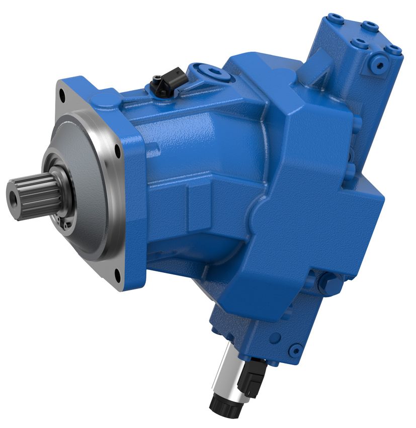
4 Scope of delivery
2
1
Fig. 1: Axial piston unit
Included in the scope of delivery:
• Axial piston unit as per order confirmation
The following parts come assembled on the unit:
• Protective covers (1)
• Protective plug/threaded plugs (2)
Bosch Rexroth AG, RE 91650-01-B/2021-07-19About this product | A36VM 19/54
5 About this product
5.1 Performance description
A Axial piston variable motor converts hydrostatic flow into mechanical rotation and
controls or regulates this. It is designed for mobile applications.
Refer to data sheet 91650 and the order confirmation for the technical data,
operating conditions and application limits of the axial piston unit.
5.2 Product description
The A36VM is a variable motor with bent-axis design for hydrostatic drives in
closed circuits.
For axial piston units with bent-axis design, the pistons (2) are arranged at an
angle to the drive shaft (1). The pistons rest directly on the drive shaft where they
generate torque depending on the pressure and swivel angle.
The specific torque and displacement can be continuously changed by controlling
the bent axis.
Closed circuit In the closed circuit, the hydraulic fluid flows from the hydraulic pump to the
hydraulic motor, then directly back to the hydraulic pump. The output direction of
rotation of the hydraulic motor is changed, e.g., by reversing the flow direction in the
hydraulic pump.
5.2.1 Axial piston unit layout
2
1 3
4
9
5
8
7
6
Fig. 2: Layout of the A36M series 10 (size 125 and 255) with double tripod joint
1 Drive shaft 5 Flushing and boost- 8 Cylinder
2 Piston pressure valve 9 Double tripod joint
3 Stroking piston 6 Control spool
4 Port plate 7 Lens plate
RE 91650-01-B/2021-07-19, Bosch Rexroth AG20/54 A36VM | About this product
5.2.2 Functional description
Motor function A hydraulic motor converts hydrostatic energy into mechanical energy. Hydraulic fluid
is directed via the port plate (4) and the lens plate (7) to the cylinder bores.
The pistons (2) in the cylinder bores execute a stroke that is converted into rotation
by the piston on the drive shaft flange.
During this, the pistons generate output torque on the drive shaft while the
cylinder (8) is carried by the double tripod joint (9).
The output torque increases with the pressure difference between the high- and
low-pressure sides and increasing displacement.
The output speed is proportional to the inward flow and inversely proportional to the
displacement of the hydraulic motor.
Flushing and The flushing and boost-pressure valve (5) is used to remove heat from the hydraulic
boost pressure valve circuit. In an open circuit, it is used exclusively for flushing the housing. In a closed
circuit, it ensures a minimum boost pressure level in addition to flushing the housing.
Hydraulic fluid is directed from the respective low-pressure side into the motor
housing. This is then fed into the reservoir, together with the leakage. In the closed
circuit, the removed hydraulic fluid must be replaced by cooled hydraulic fluid
supplied by the boost pump.
Control The swivel angle of the bent-axis rotary group is infinitely variable.
Adjusting the swivel angle changes the piston stroke and, with it, the displacement.
The swivel angle is controlled hydraulically by the stroking piston (3).
Here, the cylinder (8) is swiveled including the pistons (2) and lens plate (7).
The lens plate is mounted for easy motion in a guideway.
Increasing the swivel angle results in an increase in the displacement and specific
torque; decreasing the swivel angle results in a corresponding decrease of these
values. The output speed is dependent on the input flow and the displacement of
the hydraulic motor.
Various control devices are available depending on requirements. Information about
this can be found in data sheet 91650.
Bosch Rexroth AG, RE 91650-01-B/2021-07-19About this product | A36VM 21/54
5.3 Product identification
The axial piston unit can be identified by the name plate. The following example
shows an A36VM name plate:
1
11
10 DE - 89275 Elchingen
CNR: X1234567890Y
Typ: A36VM125EP1000000/10MWV0N4Z91010-0
9 MNR:R90XXXXXXX SC: X 2
8 SN: 12345678 7202 3
FD: 21W25
Rotation:
4
7
5
Made in Germany
6
Fig. 3: Name plate A36VM
1 Trademark 7 Manufacturing date
2 Sample category (optional) 8 Serial number
3 Internal plant designation 9 Material number of the
4 Designated area for inspection stamp axial piston unit
5 Direction of rotation (viewed on 10 Type code
drive shaft) – here: bi-directional 11 Customer material number
6 Barcode
RE 91650-01-B/2021-07-19, Bosch Rexroth AG22/54 A36VM | Transport and storage
6 Transport and storage
▶ Always observe the required ambient conditions for transport and storage;
see chapter 6.2 "Storing the axial piston unit" on page 24.
Information on unpacking can be found in chapter 7.1 "Unpacking" on page 26.
6.1 Transporting the axial piston unit
The following transportation options are available depending on weight and duration
of transport:
• Transport by hand
• Transporting with a lifting device (eye bolt or lifting strap)
Dimensions and weights Table 6: Dimensions and weights
Size 125 255
Ground kg 43.6 80
Width mm Dimensions vary by equipment. The values applicable for your axial piston unit
Height mm can be found in the installation drawing (request if necessary).
Depth mm
Weight may vary by equipment.
6.1.1 Transport by hand
Up to a specific maximum weight, axial piston units can be transported by hand for
a short distance. Observe the national regulations in your country. To prevent health
damage, we recommend renouncing any transport by hand.
CAUTION! Risk of injury due to heavy loads!
Health hazard from carrying axial piston units.
▶ Only manually transport the axial piston unit for a short period of time.
Observe the national regulations in your country for manual transport.
▶ Always use appropriate lifting, lowering and moving techniques.
▶ Use your personal protective equipment (e.g. safety goggles, safety gloves,
suitable working clothes, safety shoes).
▶ Do not transport the axial piston unit by sensitive assembled parts
(e.g. sensors or valves).
▶ Carefully place the axial piston unit on the seating to prevent it from being
damaged.
Bosch Rexroth AG, RE 91650-01-B/2021-07-19Transport and storage | A36VM 23/54
6.1.2 Transport with lifting devices
For transporting, the axial piston unit can be connected to a lifting device via an eye
bolt or a lifting strap.
Transporting with eye bolt The axial piston unit can be transported suspended from an eye bolt screwed into
the drive shaft as long as only outward (pulling) axial forces are applied.
▶ For all female threads, use a stud end from the same system of units and of
the correct size.
▶ To do this, screw an eye bolt completely into the female thread on the drive shaft.
The thread size is indicated in the installation drawing.
▶ Make sure that the eye bolt can bear the total weight of the axial piston unit
plus 20%.
You can lift the axial piston unit as shown in Fig. 4 with the eye bolt screwed into the
drive shaft.
Fig. 4: Mounting the eye bolt
Transport with lifting strap WARNING! Danger due to suspended loads!
During transport with lifting strap, the axial piston unit can topple out of the lifting
strap and cause injury.
▶ Use the widest possible lifting strap.
▶ Make sure that the axial piston unit is securely fixed with the lifting strap.
▶ Only guide the axial piston unit by hand for fine positioning and to avoid swinging.
▶ Never step or grip under suspended loads.
▶ Place the lifting strap around the axial piston unit in such a way that it does not
pass over assembled parts (e.g. valves, piping) and that the axial piston unit is
not suspended from assembled parts (see Fig. 5).
Fig. 5: Transport with lifting strap
RE 91650-01-B/2021-07-19, Bosch Rexroth AG24/54 A36VM | Transport and storage
6.2 Storing the axial piston unit
Requirement • Storage areas should be free of corrosive materials and gases.
• To prevent damage to the seals, do not operate ozone-forming equipment
(e.g. mercury-vapor lamps, high-voltage equipment, electric motors, sources of
electrical sparks or electrical discharge) in storage areas.
• Storage areas should be dry.
Recommended relative humidity ≤ 60%.
• Ideal bearing temperature: +5 °C to +20 °C.
• Minimum storage temperature: −50 °C.
• Maximum storage temperature: +60 °C.
• Keep out of direct sunlight.
• Do not stack axial piston units and store them in a shock-proof manner.
• Do not store the axial piston unit on the drive shaft or assembled parts,
e.g. sensors or valves.
• For further storage conditions, see Table 7.
▶ Check the axial piston unit monthly to ensure professional storage.
After delivery The axial piston units come in corrosion protection packaging
(corrosion protection film) provided at the factory.
Table 7 lists the maximum permissible storage times for an unpackaged
axial piston unit as per data sheet 90312.
Table 7: Storage time with factory corrosion protection
Storage conditions Standard corrosion Long-term corrosion
protection protection (optional)
Closed, dry room, uniform Maximum 12 months Maximum 24 months
temperature between +5 °C
and +20 °C. Undamaged
and closed corrosion
protection film.
The warranty will be voided if the requirements and storage conditions are not
observed or after expiration of the max. storage time (see Table 7).
How to proceed once the max. storage time elapses:
1. Check the entire axial piston unit for damage and corrosion prior to installation.
2. Perform a test run to check the axial piston unit for proper functioning and
leak-tightness.
3. If storage time exceeds 24 months, replace the shaft seal.
Once the max. storage time has elapsed, we recommend that you have the
axial piston unit checked by your Bosch Rexroth service partner.
Bosch Rexroth AG, RE 91650-01-B/2021-07-19Transport and storage | A36VM 25/54
For questions regarding repair and spare parts, contact your proper Bosch Rexroth
service partner or the service department of the manufacturer's plant of the
axial piston unit, see chapter 10.5 "Spare parts" on page 45.
After removal An uninstalled axial piston unit must be preserved with corrosion protection for the
duration of storage.
The following instructions only refer to axial piston units operated with mineral
oil-based hydraulic fluid. Other hydraulic fluids require other specific preservation
measures. In such a case, consult your local contact person; you can find their
contact information at
https://addresses.boschrexroth.com
Bosch Rexroth recommends the following procedure:
1. Clean the axial piston unit; see chapter 10.1 "Cleaning and care" on page 43.
2. Drain the axial piston unit.
3. For storage times up to 12 months: Moisten the inside of the axial piston unit
with mineral oil and fill with approx. 100 ml mineral oil.
For storage times up to 24 months: Fill the axial piston unit with VCI 329
corrosion protection (20 ml).
Fill through the drain port T1 or T2; see chapter 7.4 "Installing the
axial piston unit", Fig. 10 to Fig. 11 on page 34.
4. Plug all ports so they are airtight.
5. Coat unpainted areas of the axial piston unit with mineral oil or suitable,
easily removable corrosion protection, e.g. acid-free grease.
6. Pack the axial piston unit with desiccant in an airproof manner in corrosion
protection film.
7. Store the axial piston unit in a shock-proof manner; see "Requirement"
on page 24 in this chapter.
RE 91650-01-B/2021-07-19, Bosch Rexroth AG26/54 A36VM | Installation
7 Installation
Prior to installation, the following documents should be to hand:
• Data sheet of the axial piston unit (contains the permissible technical data,
main dimensions and circuit diagrams of standard versions)
• Installation drawing for the axial piston unit (can be obtained from your contact
person at Bosch Rexroth, if required)
• Hydraulic circuit diagram for the axial piston unit (in the data sheet and on the
installation drawing)
• Hydraulic circuit diagram for the machine/system (available from the
machine/system manufacturer upon request)
• Order confirmation (contains the order-related technical data for your
axial piston unit)
7.1 Unpacking
The axial piston unit comes in a polyethylene material (PE) corrosion protection film.
CAUTION! Danger due to falling parts!
If the packaging is not opened correctly, parts may fall out and damage the parts or
even result in injury.
▶ Place the packaging on a level underground with sufficient load-bearing capacity.
▶ Only open the packaging from the top.
▶ Remove the packaging from the axial piston unit.
▶ Check the axial piston unit for transport damage and completeness; see chapter 4
"Scope of delivery" on page 18.
▶ Dispose of the packaging in accordance with the regulations in your country.
7.2 Installation conditions
The installation position and location of the axial piston unit essentially determine
how it is installed and commissioned (such as when filling and air bleeding the
axial piston unit).
▶ Fasten the axial piston unit so that the expected forces and torque can be
transferred without any danger. The machine/system manufacturer is responsible
for sizing the fasteners.
▶ Observe the permissible radial forces on the drive shaft when transferring
output drive with radial force loading (belt drives). If necessary, store the belt
pulley separately.
▶ Make sure the axial piston unit is always filled with hydraulic fluid during
commissioning and operation. Also do this also after relatively long standstill
periods, since the axial piston unit may drain out through the hydraulic lines.
▶ Direct the leakage in the housing area to the reservoir through the highest drain
port. Use a line size that matches the port.
▶ No check valve is permissible in the drain line.
Bosch Rexroth AG, RE 91650-01-B/2021-07-19Installation | A36VM 27/54
▶ To prevent the transmission of structure-borne noise, use elastic elements
to decouple all connecting lines from all vibration-capable components
(e.g. reservoir, frame parts).
▶ Make sure that the drain line and return line flow into the reservoir below the
minimum fluid level under all operating conditions. This prevents foaming.
▶ Make sure that the working environment at the installation site is completely
free of dust and foreign substances. The axial piston unit should be clean when
installed. Contamination of the hydraulic fluid can considerably affect the
function and service life of the axial piston unit.
▶ Use fiber-free cleaning cloth.
▶ Use suitable, mild cleaning agents to remove lubricants and other heavy
contamination. Do not allow cleaning agents to enter into the hydraulic system.
RE 91650-01-B/2021-07-19, Bosch Rexroth AG28/54 A36VM | Installation
7.3 Installation position
The following installation positions are permissible. The pipeline routing shown
illustrates the basic layout.
Port F is part of the external piping and must be provided on the customer side
to make filling and air bleeding easier.
7.3.1 Below-reservoir installation (standard)
Below-reservoir installation means that the axial piston unit is installed outside of
the reservoir below the minimum fluid level.
Recommended installation position: 1 and 2.
1 2
F F
ht min ht min
hmin hmin
T1
T2
T2
T1
Fig. 6: Below-reservoir installation A36VM with installation position 1–2
T1, T2 Drain port ht min Minimum required immersion depth
(200 mm)
F Filling/air bleeding
hmin Minimum required distance to
reservoir bottom (100 mm)
Table 8: Below-reservoir installation
Installation position Air bleed Filling
1 (drive shaft horizontal) F T1
2 (drive shaft horizontal) F T2
Bosch Rexroth AG, RE 91650-01-B/2021-07-19Installation | A36VM 29/54
7.3.2 Above-reservoir installation
Above-reservoir installation means that the axial piston unit is installed above
the minimum fluid level of the reservoir.
1 2
F F
T1
T2
T2
T1
ht min ht min
hmin hmin
Fig. 7: Above-reservoir installation A36VM with installation position 3–4
T1, T2 Drain port ht min Minimum required immersion depth
(200 mm)
F Filling/air bleeding
hmin Minimum required distance to
reservoir bottom (100 mm)
Table 9: Above-reservoir installation
Installation position Air bleed Filling
3 (drive shaft horizontal) F T1 (F)
4 (drive shaft horizontal) F T2 (F)
RE 91650-01-B/2021-07-19, Bosch Rexroth AG30/54 A36VM | Installation
7.4 Installing the axial piston unit
7.4.1 Preparation
1. Check the specifications on the name plate to see you have the correct
axial piston unit.
2. Compare the material number and designation (type code) with the parameters
in the order confirmation.
If the material number for the axial piston unit does not match the one in
the order confirmation, contact your local contact person for clarification.
You can find their contact information at
https://addresses.boschrexroth.com
3. Before installing, completely drain the axial piston unit to prevent mixing with
the hydraulic fluid used in the machine/system.
4. Check the permissible direction of rotation of the axial piston unit (on the name
plate) and make sure that this corresponds to the direction of rotation of the
intended motor function.
L
W R
Fig. 8: Direction of rotation
W Bi-directional (can rotate counter-clockwise and clockwise)
L Counter-clockwise
R Clockwise
The direction of rotation as indicated on the name plate determines the direction
of rotation of the axial piston unit as viewed on the drive shaft; see chapter 5.3
"Product identification" on page 21.
7.4.2 Dimensions
For standard versions, the data sheet 91650 contains all required installation
dimensions as well as the position and dimensions of the ports. If necessary,
an installation drawing can be requested. Also observe the manuals provided by the
manufacturers of the other hydraulic components when selecting the required tools.
7.4.3 General instructions
Follow these general notices when installing the axial piston unit:
• Note that certain installation positions will affect the control system.
Gravity, dead weight and case pressure can cause minor characteristic shifts
and changes in response time.
Bosch Rexroth AG, RE 91650-01-B/2021-07-19Installation | A36VM 31/54
• If a shared drain line is used for several units, make sure that the respective case
pressure in each unit is not exceeded. The shared drain line must be dimensioned
to ensure that the maximum permissible case pressure of all connected units is
not exceeded in any operating condition, particularly at cold start. If this is not
possible, separate drain line must be laid, if necessary.
How the axial piston unit is installed depends on the connecting elements to the
output side. The following descriptions explain the installation of the axial piston unit:
• With a coupling
• On a gearbox
7.4.4 Installation with a coupling
The following describes how to install the axial piston unit with a coupling:
NOTICE! Danger from improper handling!
Product can be damaged!
▶ Do not install the coupling hub on the drive shaft of the axial piston unit by
striking it.
1. Install the specified coupling half on the drive shaft of the axial piston unit
according to the instructions of the coupling manufacturer.
The drive shaft of the axial piston unit is equipped with a female thread. Use this
female thread to pull the coupling element onto the drive shaft. The size of the
female thread can be seen in the installation drawing.
2. Make sure that the installation location is clean and free from dirt and foreign
particles.
3. Clamp the coupling hub onto the drive shaft or ensure permanent lubrication
of the drive shaft. This prevents the formation of frictional corrosion and the
associated wear.
4. Transport the axial piston unit to the installation location.
5. Assemble the clutch on the drive shaft of the machine in accordance with the
specifications provided by the coupling manufacturer.
Do not fasten down the axial piston unit until the coupling has been correctly
installed.
6. Fasten the axial piston unit at the installation location.
7. Align the drive shaft of the axial piston unit and the drive shaft of the machine so
that there is no angular deviation.
Make sure no excessive axial and radial forces are acting on the drive shaft.
8. Details on the required tools and tightening torques for the mounting bolts are
available from the machine/system manufacturer.
RE 91650-01-B/2021-07-19, Bosch Rexroth AGYou can also read