Windsor-Essex REGIONAL INFRASTRUCTURE PLAN December 22, 2015 - Hydro One
←
→
Page content transcription
If your browser does not render page correctly, please read the page content below
Windsor-Essex REGIONAL INFRASTRUCTURE PLAN December 22, 2015

Windsor-Essex – Regional Infrastructure Plan                                      December 22, 2015

                                        [This page is intentionally left blank]

                                                                                                 2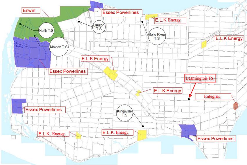
Windsor-Esssex – Regional Infrastructure
                          I              Pllan   December 222, 2015

Prepared and
         a endorsed
                  d by:

Company y
Hydro Onne Networks Inc.
                       I (Lead Traansmitter)
Independeent Electricity
                       y System Opeerator
E.L.K. En
        nergy Inc.
Entegrus Powerlines
         P            In
                       nc.
EnWin Uttilities Ltd.
Essex Pow
        werlines Corp  poration
Hydro Onne Networks Inc.
                       I (Distributtion)

                                                                 3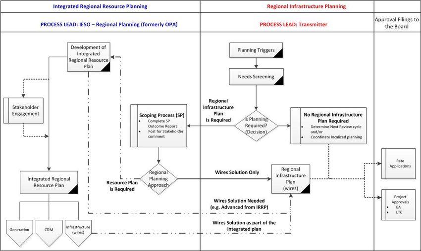
Windsor-Essex – Regional Infrastructure Plan                                      December 22, 2015

                                        [This page is intentionally left blank]

                                                                                                 4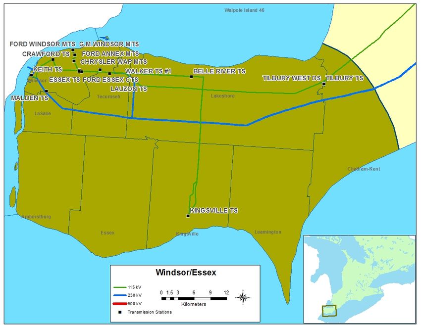
Windsor-Essex – Regional Infrastructure Plan                                                December 22, 2015

DISCLAIMER
This Regional Infrastructure Plan (“RIP”) report was prepared for the purpose of developing an electricity
infrastructure plan to address all near and mid-term needs identified in previous planning phases and also
any additional near and mid-term needs identified based on new and/or updated information provided by
the RIP Working Group.

The preferred solution(s) that have been identified in this report may be reevaluated based on the findings
of further analysis. The load forecast and results reported in this RIP report are based on the information
provided and assumptions made by the participants of the RIP Working Group.

Working Group participants, their respective affiliated organizations, and Hydro One Networks Inc.
(collectively, “the Authors”) make no representations or warranties (express, implied, statutory or
otherwise) as to the RIP report or its contents, including, without limitation, the accuracy or completeness
of the information therein and shall not, under any circumstances whatsoever, be liable to each other, or to
any third party for whom the RIP report was prepared (“the Intended Third Parties”), or to any other third
party reading or receiving the RIP report (“the Other Third Parties”), for any direct, indirect or
consequential loss or damages or for any punitive, incidental or special damages or any loss of profit, loss
of contract, loss of opportunity or loss of goodwill resulting from or in any way related to the reliance on,
acceptance or use of the RIP report or its contents by any person or entity, including, but not limited to,
the aforementioned persons and entities.

                                                                                                           5
Windsor-Essex – Regional Infrastructure Plan                                      December 22, 2015

                                        [This page is intentionally left blank]

                                                                                                 6
Windsor-Essex – Regional Infrastructure Plan December 22, 2015
EXECUTIVE SUMMARY
THIS REGIONAL INFRASTRUCTURE PLAN (“RIP”) WAS PREPARED BY
HYDRO ONE AND THE WORKING GROUP IN ACCORDANCE WITH THE
ONTARIO TRANSMISSION SYSTEM CODE REQUIREMENTS. IT
IDENTIFIES INVESTMENTS IN TRANSMISSION FACILITIES,
DISTRIBUTION FACILITIES, OR BOTH, THAT SHOULD BE DEVELOPED
AND IMPLEMENTED TO MEET THE ELECTRICITY INFRASTRUCTURE
NEEDS WITHIN THE WINDSOR-ESSEX REGION.
The participants of the RIP Working Group included members from the following organizations:
Hydro One Networks Inc. (Transmission)
Independent Electricity System Operator
E.L.K. Energy Inc.
Entegrus Powerlines Inc.
EnWin Utilities Ltd.
Essex Powerlines Corporation
Hydro One Networks Inc. (Distribution)
This RIP provides a consolidated summary of needs and recommended plans for Windsor-Essex Region.
No long-term needs (10 to 20 years) and associated plans have been identified.
This RIP is the final phase of the regional planning process and it follows the completion of the Windsor-
Essex Region Integrated Regional Resource Plan (“IRRP”) by the IESO in April 2015 [1].
The major infrastructure investments planned, or being planned, for the Windsor-Essex Region over the
near and medium-term identified in the various phases of the regional planning process are given in the
table below.
No. Project I/S Date Cost
Supply to Essex County Transmission Reinforcement
1* June 2018 $77.4M
(SECTR TX) Project
Supply to Essex County Transmission Reinforcement
2* June 2018 $19.3M
(SECTR DX) Project
3 Replacement of Keith end-of-life autotransformers 2020 $45M
4 Replacement of Kingsville end-of-life transformers 2018 $12M
230kV/115kV circuit and 27.6kV feeder reconfiguration at Keith TS
5 2018 $63M
due to Gordie Howe International Bridge (GHIB) Project
6 Additional feeder position at Malden TS TBD TBD
7 Decommission of Tilbury TS 2019 TBD
8 Decommission of T1 Transformer at Keith TS TBD TBD
* These projects address the needs identified in the Windsor-Essex IRRP study for the region in the near and medium-term.
7
Windsor-Essex – Regional Infrastructure Plan                                             December 22, 2015

In accordance with the Regional Planning process, the Regional Plan should be reviewed and/or updated
at least every five years. Should there be any new needs that emerge due to a change in load forecast or
any other reason, the next regional planning cycle will be started earlier to address the need.

                                                                                                           8
Windsor-Essex – Regional Infrastructure Plan                                                                                             December 22, 2015

TABLE OF CONTENTS
Disclaimer ..................................................................................................................................................... 5
Executive Summary ...................................................................................................................................... 7
Table of Contents .......................................................................................................................................... 9
List of Figures ............................................................................................................................................. 11
List of Tables .............................................................................................................................................. 11
1. Introduction .......................................................................................................................................... 13
    1.1 Scope and Objectives.................................................................................................................. 14
    1.2 Structure...................................................................................................................................... 14
2. Regional Planning Process ................................................................................................................... 15
    2.1 Overview .................................................................................................................................... 15
    2.2 Regional Planning Process ......................................................................................................... 15
    2.3 RIP Methodology ....................................................................................................................... 18
3. Regional Characteristics ....................................................................................................................... 19
4. Transmission Facilities Completed Over the Last Ten Years or Currently Underway ........................ 23
5. Load Forecast And Other Assumptions ............................................................................................... 25
    5.1 Historical Demand ...................................................................................................................... 25
    5.2 Contribution of CDM and DG .................................................................................................... 26
    5.3 Gross and Net Demand Forecast ................................................................................................ 26
    5.4 Other Study Assumptions ........................................................................................................... 27
6. Regional Needs..................................................................................................................................... 28
7. Regional Infrastructure Plans ............................................................................................................... 31
    7.1 Supply to Essex County Transmission Reinforcement (SECTR) Project .................................. 31
         7.1.1 Description ........................................................................................................................ 31
         7.1.2 Recommended Plan and Current Status ............................................................................ 31
    7.2 Keith TS End-of-Life Auto-Transformer Replacement.............................................................. 35
         7.2.1 Description ........................................................................................................................ 35
         7.2.2 Recommended Plan and Current Status ............................................................................ 35
    7.3 Kingsville TS End-of-Life Transformer Replacement ............................................................... 35
         7.3.1 Description ........................................................................................................................ 35
         7.3.2 Recommended Plan .......................................................................................................... 35
    7.4 Gordie Howe International Bridge (GHIB) ................................................................................ 35
         7.4.1 Description ........................................................................................................................ 35
         7.4.2 Recommended Plan and Current Status ............................................................................ 36
8. Other Projects ....................................................................................................................................... 37
    8.1 Malden TS Additional Feeder Positions ..................................................................................... 37
         8.1.1 Description ........................................................................................................................ 37
         8.1.2 Recommended Plan and/or Current Status ....................................................................... 37
    8.2 Tilbury TS Transformer End-of-Life Replacement .................................................................... 37
         8.2.1 Description ........................................................................................................................ 37
         8.2.2 Recommended Plan and Current Status ............................................................................ 38
    8.3 Keith TS T1 Transformer End-of-Life Replacement ................................................................. 38
         8.3.1 Description ........................................................................................................................ 38

                                                                                                                                                                9
Windsor-Essex – Regional Infrastructure Plan                                                                                          December 22, 2015

       8.3.2 Recommended Plan and Current Status ............................................................................ 39
9. Conclusion ............................................................................................................................................ 40
10. References ............................................................................................................................................ 42
Appendix A. Gross Forecast by Subsystem & Station ............................................................................... 43
Appendix B. Conservation Assumptions by Subsystem & Station ............................................................ 44
Appendix C. Distributed Generation Assumptions by Subsystem & Station ............................................. 45
Appendix D. Reference Planning Forecast by Subsystem & Station ......................................................... 46
Appendix E. List of Acronyms ................................................................................................................... 47

                                                                                                                                                          10
Windsor-Essex – Regional Infrastructure Plan December 22, 2015
LIST OF FIGURES
Figure 1-1 Geographical Map of Windsor-Essex Region ........................................................................... 13
Figure 2-1 Regional Planning Process Flowchart ....................................................................................... 17
Figure 2-2 RIP Methodology ...................................................................................................................... 18
Figure 3-1 LDC Service Territories ............................................................................................................ 19
Figure 3-2 Windsor-Essex Area Subsystems/Single Line Diagram ........................................................... 20
Figure 5-1 Historical Load Demand in Windsor-Essex Region ................................................................. 25
Figure 5-2 Reference Forecast in Windsor-Essex Region .......................................................................... 27
Figure 6-1 Historical and Forecast Demand of Kingsville-Leamington Subsystem .................................. 29
Figure 7-1 Schematic Electrical Diagram of the Proposed Facilities ......................................................... 33
Figure 7-2 Preliminary Distribution Feeder Plans for SECTR Project ....................................................... 34
Figure 7-3 Gordie Howe International Bridge (GHIB) Project .................................................................. 36
LIST OF TABLES
Table 3-1 Stations Included in the Windsor-Essex Region ........................................................................ 21
Table 3-2 Transmission Connected Generation Facilities in the Region .................................................... 22
Table 6-1 Summary of Needs ..................................................................................................................... 30
Table 9-1 Project Under Development ....................................................................................................... 40
Table 9-2 Project Pending Decision............................................................................................................ 41
11Windsor-Essex – Regional Infrastructure Plan December 22, 2015
[This page is intentionally left blank]
12Windsor-Essex – Regional Infrastructure Plan December 22, 2015
1. INTRODUCTION
THIS REPORT PRESENTS THE REGIONAL INFRASTRUCTURE PLAN
(“RIP”) TO ADDRESS THE ELECTRICITY NEEDS OF THE WINDSOR-ESSEX
REGION.
The report was prepared by Hydro One Networks Inc. (Transmission) (“Hydro One”) and documents the
results of the joint study carried out by Hydro One, EnWin Utilities Ltd. (“EnWin”), Essex Powerlines
Corporation, E.L.K. Energy Inc. (“E.L.K Energy”), Entegrus Inc. (“Entegrus”), Hydro One Networks Inc.
(Distribution) (“Hydro One Distribution), and the Independent Electricity System Operator (“IESO”) in
accordance with the regional planning process established by the Ontario Energy Board (“OEB”) in 2013.
The Windsor-Essex Region comprises the City of Windsor, Town of Amherstburg, Town of Essex, Town
of Kingsville, Town of Lakeshore, Town of LaSalle, Municipality of Leamington, Town of Tecumseh,
the western portion of the Municipality of Chatham-Kent and the Township of Pelee Island. The map of
the region is shown in Figure 1-1 below.
The Windsor-Essex area is supplied from a combination of generation located in the region and from the
Ontario grid via a network of 230 kV and 115 kV transmission lines and stations. The region peak
electricity demand of about 800 MW is provided from three 230 kV and fourteen 115 kV step-down
transformer stations.
Figure 1-1 Geographical Map of Windsor-Essex Region
13Windsor-Essex – Regional Infrastructure Plan December 22, 2015
1.1 Scope and Objectives
This RIP report examines the needs in the Windsor-Essex Region. Its objectives are to: identify new
supply needs that may have emerged since previous planning phases (e.g., Needs Assessment (“NA”),
Scoping Assessment (“SA”), Local Plan (“LP”), and/or Integrated Regional Resource Plan (“IRRP”));
assess and develop wires plans to address these needs; provide the status of wires planning currently
underway or completed for specific needs; and identify investments in transmission and distribution
facilities or both that should be developed and implemented to meet the electricity infrastructure needs
within the region.
Planning activities for the Windsor-Essex Region were already underway before the new regional
planning process was introduced. The NA and SA phases were deemed to be complete and the Windsor-
Essex Region was identified as a “transitional” region. The planning status for the region was considered
to be in the IRRP phase of the regional planning process. An IRRP for the region was completed in April
2015.
The RIP reviews factors such as the load forecast, transmission and distribution system capability along
with any updates with respect to local plans, conservation and demand management (“CDM”), renewable
and non-renewable generation development, and other electricity system and local drivers that may
impact the need and alternatives under consideration.
The scope of this RIP is as follows:
A consolidated report of the needs and relevant plans to address near and mid-term needs (2015-
2025) identified in previous planning phases (NA, SA, LP, and/or IRRP).
Identification of any new needs over the 2015-2025 period and a wires plan to address these
needs based on new and/or updated information.
Develop a plan to address any longer term needs identified by the Working Group.
The IRRP or RIP Working Group did not identify any long term needs at this time. If required, further
assessment will be undertaken in the next planning cycle because adequate time is available to plan for
required facilities.
1.2 Structure
The rest of the report is organized as follows:
Section 2 provides an overview of the regional planning process.
Section 3 describes the region.
Section 4 describes the transmission work completed over the last ten years.
Section 5 describes the load forecast and study assumptions used in this assessment.
Section 6 describes the regional needs.
Section 7 provides a summary of regional plans.
Section 8 provides summary of other projects.
Section 9 provides the conclusion and next steps.
14Windsor-Essex – Regional Infrastructure Plan December 22, 2015
2. REGIONAL PLANNING PROCESS
2.1 Overview
Planning for the electricity system in Ontario is done at essentially three levels: bulk system planning,
regional system planning, and distribution system planning. These levels differ in the facilities that are
considered and the scope of impact on the electricity system. Planning at the bulk system level typically
looks at issues that impact the system on a provincial level, while planning at the regional and distribution
levels looks at issues on a more regional or localized level.
Regional planning looks at supply and reliability issues at a regional or local area level. Therefore,
it largely considers the 115 kV and 230 kV portions of the power system that supply various parts of
the province.
2.2 Regional Planning Process
A structured regional planning process was established by the Ontario Energy Board in 2013 through
amendments to the Transmission System Code (“TSC”) and Distribution System Code (“DSC”). The
process consists of four phases: the Needs Assessment 1 (“NA”), the Scoping Assessment (“SA”), the
Integrated Regional Resource Plan (“IRRP”), and the Regional Infrastructure Plan (“RIP”).
The regional planning process begins with the NA phase which is led by the transmitter to determine if
there are regional needs. The NA phase identifies the needs and the Working Group determines whether
further regional coordination is necessary to address them. If no further regional coordination is required,
further planning is undertaken by the transmitter and the impacted local distribution company (“LDC”) or
customer and develops a Local Plan (“LP”) to address them. These needs are local in nature and can be
best addressed by a straight forward wires solution.
In situations where identified needs require coordination at the regional or sub-regional levels, the IESO
initiates the SA phase. During this phase, the IESO, in collaboration with the transmitter and impacted
LDCs, reviews the information collected as part of the NA phase, along with additional information on
potential non-wires alternatives, and makes a decision on the most appropriate regional planning
approach. The approach is either a RIP, which is led by the transmitter, or an IRRP, which is led by the
IESO. If more than one sub-region was identified in the NA phase, it is possible that a different approach
could be taken for different sub-regions.
The IRRP phase will generally assess infrastructure (wires) versus resource (CDM and Distributed
Generation) options at a higher or more macro level, but sufficient to permit a comparison of options. If
the IRRP phase identifies that infrastructure options may be most appropriate to meet a need, the RIP
phase will conduct detailed planning to identify and assess the specific wires alternatives and recommend
a preferred wires solution. Similarly, resource options which the IRRP identifies as best suited to meet a
1
Also referred to as Needs Screening
15Windsor-Essex – Regional Infrastructure Plan December 22, 2015
need are then further planned in greater detail by the IESO. The IRRP phase also includes IESO led
stakeholder engagement with municipalities and establishes a Local Advisory Committee in the region or
sub-region. Since the Windsor-Essex Region was in transition to the new regional planning process, the
IESO led IRRP engagement for this region was initiated after the completion of the IRRP.
The RIP phase is the final stage of the regional planning process and involves: confirmation of previously
identified needs; identification of any new needs that may have emerged since the start of the planning
cycle; and development of a wires plan to address the needs where a wires solution would be the best
overall approach. This phase is led and coordinated by the transmitter and the deliverable of this stage is a
comprehensive report of a wires plan for the region. Once completed, this report can be referenced in rate
filing submissions or as part of LDC rate applications with a planning status letter provided by the
transmitter. Reflecting the timelines provisions of the RIP, plan level stakeholder engagement is not
undertaken at this stage. However, stakeholder engagement at a project specific level will be conducted as
part of the project approval requirement.
The regional planning process specifies a 20 year planning assessment period for the IRRP. The RIP
focuses on the wires options and, given the forecast uncertainty and the fact that adequate time is
available to identify and plan new wire facilities in subsequent planning cycles, a study period of 10 years
is considered adequate for the RIP. The exception would be the case where major transmission
infrastructure investments are required. In these cases the RIP would review and assess longer term needs
and develop a longer term plan.
To efficiently manage the regional planning process in the region, Hydro One has been undertaking wires
planning activities in collaboration with the IESO and LDCs for the region as part of and/or in parallel
with:
Planning activities that were already underway in the region prior to the new regional planning
process taking effect.
Participating in and conducting wires planning as part of the IRRP for the region.
Working and planning connection capacity requirements with the LDCs.
Figure 2-1 illustrates the various phases of the regional planning process (NA, SA, IRRP, and RIP) and
their respective phase trigger, lead, and outcome.
16Windsor-Essex – Regional Infrastructure Plan December 22, 2015
Figure 2-1 Regional Planning Process Flowchart
17Windsor-Esssex – Regional Infrastructure
I Pllan December 222, 2015
2.3 RIP
R Methodology
The RIP process
p is a fo
our step proceess as shown in Figure 2-2 below.
1. Data Gathering:
G Thhe first step of
o the RIP pro ocess is the revview of plannning assessmeent data collected
in thee previous stag ges of the reggional planninng process. Hyydro One colllects this infoormation and
reviewws it with the Working Gro oup to reconffirm or updatee the informattion as requirred. The data
colleccted includes:
NetN peak demaand forecast at a the transforrmer station leevel. This inccludes the effeect of any
diistributed genneration or conservation an nd demand maanagement prrograms.
Existing
E area network
n and capabilities
c in
ncluding any bbulk system ppower flow asssumptions.
Other
O data andd assumptionss as applicablee such as asseet conditions; load transferr capabilities, and
prreviously com mmitted transm mission and distribution
d syystem plans.
2. Techn nical Assessm ment: The seco ond step is a technical
t asseessment to revview the adeqquacy of the
region nal system inccluding any previously
p ideentified needss. Additional nnear and mid-term needs m may
be ideentified at thiss stage.
3. Altern native Develo opment: The third
t step is th
he developmeent of wires ooptions to adddress the needds and
to comme up with a preferred alteernative based d on an assesssment of techhnical consideerations,
feasibbility, environnmental impacct and costs.
4. Impleementation Plan: The fourtth and last step p is the devellopment of thhe implementaation plan forr the
preferrred alternativve.
Figure 2-2
2 RIP Method
dology
18Windsor-Essex – Regional Infrastructure Plan December 22, 2015
3. REGIONAL CHARACTERISTICS
THE WINDSOR-ESSEX REGION COMPRISES THE CITY OF WINDSOR,
TOWN OF AMHERSTBURG, TOWN OF ESSEX, TOWN OF KINGSVILLE,
TOWN OF LAKESHORE, TOWN OF LASALLE, MUNICIPALITY OF
LEAMINGTON, TOWN OF TECUMSEH, THE WESTERN PORTION OF THE
MUNICIPALITY OF CHATHAM-KENT AND THE TOWNSHIP OF PELEE
I SLAND.
The region is served by five LDCs: EnWin, Essex Powerlines Corporation, E.L.K. Energy, Entegrus, and
Hydro One Distribution, whose service territories are shown in Figure 3-1. EnWin and Hydro One
Distribution are directly connected to the transmission system, while the three other LDCs have low
voltage connections.
Figure 3-1 LDC Service Territories
19Windsor-Esssex – Regional Infrastructure
I Pllan December 222, 2015
The region peak electriicity demand of about 800 MW is suppllied from a coombination of local generaation
and from connection too the Ontario grid via a nettwork of 230 kV and 115 kkV transmissiion lines and
hown in Figurre 3-2 below.
stations sh
Figure
F 3-2 Win
ndsor-Essex Area
A Subsystem
ms/Single Lin
ne Diagram
The main transmissionn corridor in th
he region con
nnects with thhe rest of the H
Hydro One syystem at Chattham
g Station (“SS
Switching S”) and conneects the Ontarrio transmissioon system wiith the Michiggan transmission
system at Keith TS.
The region’s 115 kV network conneects to the 230 0 kV transmisssion system at Keith TS aand Lauzon T TS via
two auto-ttransformers in each statio
on. About 65%% of the area load is suppliied by fourteeen step-downn
transform
mers stations connected to thhe 115 kV neetwork, while the balance iis supplied byy three step-doown
transform
mer stations co
onnected to thhe 230 kV nettwork. Table 33-1 lists the region’s step-ddown transforrmer
stations.
There are six customerr-owned generating plants in the region connecting aat the 230 kV and 115 kV llevels
mbined contraact capacity of
with a com o 927 MW. In addition, thhe distributed generation coonnected at
various lo
ocations to low
w-voltage (“L LV”) feeders in
i the region account for aabout 65 MW of effective
capacity. Table 3-1 listt the region’s transmission connected geenerations.
20Windsor-Essex – Regional Infrastructure Plan December 22, 2015
The transmission system in the region can be divided into two “nested” sub-systems:
The Kingsville-Leamington subsystem: customers supplied from Kingsville TS and
The J3E-J4E subsystem: customers supplied from stations connected to the Windsor-Essex 115
kV system, as well as customers supplied from the 230/27.6 kV Lauzon DESN.
As can be noted in Figure 3-2 below, the Kingsville-Leamington subsystem is nested within the J3E-J4E
subsystem. Therefore, increasing supply to the Kingsville-Leamington subsystem or transferring load
from the existing Kingsville TS to a new 230 kV TS will impact the supply and demand balance in the
J3E-J4E subsystem.
Table 3-1 Stations Included in the Windsor-Essex Region
Station (DESN) Voltage Level (kV) Supply Circuits Connected Customer(s)
Belle River TS (T1/T2) 115/27.6 K2Z/K6Z Hydro One Distribution
E.L.K. Energy
Kingsville TS
115/27.6 K2Z/K6Z Essex Powerlines Corp.
(T1/T2/T3/T4)
Hydro One Networks Inc.
EnWin Utilities Ltd.
Lauzon TS (T5/T6/T7/T8) 230/27.6 C23Z/C24Z
Hydro One Distribution
Tilbury West DS 115/27.6 K2Z Hydro One Distribution
Tilbury TS (T1) 115/27.6 K2Z Hydro One Distribution
Chrysler WAP MTS 115/27.6 E8F/E9F EnWin Utilities Ltd.
Crawford TS (T3/T4) 115/27.6 J3E/J4E EnWin Utilities Ltd.
Essex TS (T5/T6) 115/27.6 Z7E/ EnWin Utilities Ltd.
Ford Annex MTS 115/27.6 E8F/E9F EnWin Utilities Ltd.
Ford Essex CTS 115/13.8 Z1E/Z7E EnWin Utilities Ltd.
Ford Windsor MTS 115/27.6 E8F/E9F EnWin Utilities Ltd.
G.M. Windsor MTS 115/27.6 E8F/E9F EnWin Utilities Ltd.
Brighton Beach Power LP
Keith TS (T1) 115/27.6 C21J/C22J West Windsor Power
EnWin Utilities Ltd.
Keith TS (T22/T23) 230/27.6 C21J/C22J Essex Powerlines Corp.
Hydro One Distribution
EnWin Utilities Ltd.
Malden TS (T1/T2) 230/ 27.6 C21J/C22J Essex Powerlines Corp.
Hydro One Distribution
Walker MTS #2 115/27.6 Z1E/Z7E EnWin Utilities Ltd.
Walker TS #1 (T3/T4) 115/27.6 Z1E/Z7E EnWin Utilities Ltd.
21Windsor-Essex – Regional Infrastructure Plan December 22, 2015
Table 3-2 Transmission Connected Generation Facilities in the Region
Contract Summer
Contract Connection
Technology Station Name Capacity Effective
Expiry Date Point
(MW) Capacity (MW)
Combined Cycle
Brighton Beach Power
Generating Dec. 31, 2024 Keith TS 541 526
Station
Facility
J2N
West Windsor Power May 31, 2031 128 107
Combined Heat (Keith TS)
and Power TransAlta Windsor Dec. 1, 2031 Z1E 74 74
(CHP) East Windsor
Nov. 5, 2029 E8F/E9F 84 80
Cogeneration Centre
Gosfield Wind Project Jan. 12, 2029 K2Z 51 8
Renewables Point Aux Roches
Dec. 5, 2031 K6Z 49 8
Wind Farm
22Windsor-Essex – Regional Infrastructure Plan December 22, 2015
4. TRANSMISSION FACILITIES COMPLETED
OVER THE LAST TEN YEARS OR CURRENTLY
UNDERWAY
OVER THE LAST 10 YEARS A NUMBER OF TRANSMISSION PROJECTS
HAVE BEEN COMPLETED OR ARE UNDERWAY BY HYDRO ONE, AIMED
AT IMPROVING THE SUPPLY TO THE WINDSOR-ESSEX REGION. A BRIEF
LISTING OF THE COMPLETED PROJECTS OVER THE LAST 10 YEARS IS
GIVEN BELOW:
Belle River TS (May 2006): Built a new 2-25/33/42 MVA 115/27.6 kV transformer station in the
Town of Lakeshore supplied from 115 kV circuits K2Z/K6Z. The station provides additional load
supply capability to meet the load requirements of Hydro One Distribution customers in the Town of
Lakeshore. The connection of new station required the untwining of K6Z to obtain two circuits (K2Z
and K6Z) with K6Z on the north side of the towers. The new K2Z circuit section which only extends
to Belle River TS was then connected to the then existing K2Z circuit just outside of Lauzon TS.
Essex TS (October 2008): The station was refurbished with new 2-50/66/83 MVA 115/27.6 kV
transformers. The 115 kV supply circuits were reconfigured to mitigate exposure to customer load
loss for loss of a single transmission element under certain system conditions.
Malden TS: Transformer T2 75/100/125 230/27.6 kV was replaced (July 2010) and T1 was replaced
(December 2011).
Keith TS: T23 transformer 50/67/83 MVA 230/27.6 kV was replaced (October 2008) and T22
transformer 50/67/83 MVA 230/27.6 kV was replaced (December 2013).
Walker TS #1: Reactor installation for short circuit mitigation (June 2011).
Kingsville TS: Reactor installation for short circuit mitigation (November 2011).
Keith TS: Reactor installation for short circuit mitigation (April 2012).
Lauzon TS: Three breakers were replaced: SC2Q (June 2012), SC3E (April 2012) and SC4J (April
2012).
Keith TS: Six breakers were replaced: SC11K (May 2014), SC11SC (May 2014), SC1B (June 2014),
T11P (August 2014), T12P (October 2014), SC2Y (January 2015).
23Windsor-Essex – Regional Infrastructure Plan December 22, 2015
The following projects are currently underway:
Crawford TS: is a 115/28 kV, with two 50/67/83 MVA units in Windsor. It supplies the downtown
Windsor area with a current peak load of 60 MW. The existing T3 transformer is at the end-of-life
with leaky fittings and headboard. The T3 fire suppression system and separation wall also needs to
be upgraded to current standards. The current plan is to replace T3 transformer and install neutral
grounding reactors on the T3 and T4 transformer units. The project includes protection and control
upgrades and relocation of battery, necessary spill containment facilities at Crawford TS. The project
is under execution for $8.46 million with an in-service date of December 15, 2016. There are no cost
implications for the LDCs. Once this project is complete the station will meet the current design
standards.
24Windsor-Esssex – Regional Infrastructure
I Pllan December 222, 2015
5. LOAD
L FOREC
F AST A ND OT
THER A
ASSUM PTION
NS
THE FO
ORECAST S REFLECCT THE EX
XPECTEDD PEAK DE
EMAND AAT EACH
STATIO
ON UNDE R EXTREM ME WEATTHER CON
NDITIONSS, BASED ON
FACTOORS SUCHH AS POPU
ULATION, HOUSEHHOLD ANDD ECONO MIC
GROWT TH, CONS
SISTENT WITH
W MU NICIPAL PLANNINNG ASSUMMPTIONS..
5.1 Historical
H Deemand
The peak demand in th
he Windsor-Essex Region has
h declined ffrom a high oof 1060 MW iin the summeer of
pproximately 800 MW in both
2006 to ap b 2013 and
d 2014.
Figure 5-11 shows the historical
h summmer peak dem mand observeed in the regioon from 2004 to 2014. A
noticeablee peak in 2006 is coincidennt with the alll-time peak inn Ontario powwer demand, w while a dip inn
2008 and 2009 shows the t area’s resp ponse to the global
g recessiion. There is a large conceentration of
automotiv ve manufacturring facilities in the City of Windsor. Thhe sector is a major economic driver annd
electricity
y user within the
t region. Th he decline in Ontario’s maanufacturing ssector and thee 2008/09
economicc downturn haave both contrributed to a deecline in elecctricity use in the region.
While thee manufacturin ntinues to facee challenges inn recovering,, economic diiversification is
ng sector con
changing the region’s growth
g and ellectricity use. The five-yeaar Windsor-Essex Regionaal Economic
Roadmap, released in 2011,
2 identifies nine industry groups thaat hold growtth potential foor the region,
including advanced maanufacturing, tourism, and agri-businesss.
Figure 5-1 Historical
H Load
d Demand in W
Windsor-Essexx Region
The peak demand in th
he Kingsville--Leamington area has also experienced fluctuations oover the 20044-
2014 period as shown in
i Figure 6-1.
25Windsor-Essex – Regional Infrastructure Plan December 22, 2015
5.2 Contribution of CDM and DG
In developing the planning forecast, the following process was used to assess the Windsor-Essex Region:
a) First, “gross demand” is established. Gross demand reflects the forecast developed and provided
by the area LDCs and is influenced by a number of factors such as economic, household and
population growth.
b) Second, “net demand” is derived by reducing the gross demand by expected savings from
improved building codes and equipment standards, customer response to time-of-use pricing, and
projected province-wide CDM programs. This information is provided by the IESO.
c) Lastly, a “planning forecast” is determined by reducing net demand by the contribution in the
area from existing, committed and forecast DG. This information is provided by the IESO.
5.3 Gross and Net Demand Forecast
Summer peak gross non-coincident demand forecasts for the 20-year planning horizon were provided by
EnWin and Hydro One Distribution, the two LDCs which are directly connected to the transmission
system, for each of the transformer stations in the area. The forecasts from Hydro One Distribution
include forecasts provided by the appropriate embedded LDCs.
The development of the load forecast for this RIP report followed a two-stage process:
(a) Using the forecast provided by the LDCs, the year by year growth rate for each station was first
developed.
(b) The 2014 summer actual peak load, corrected for extreme weather, for each station was obtained.
(c) The growth rates from (a) were then applied to the 2014 summer peak load of (b) to obtain the
gross load forecast for each station for extreme weather conditions.
The gross load forecasts, for extreme weather conditions, by station and by subsystem are shown in
Appendix A. This load forecast reflects the following:
A shift of load, commencing in 2016, from Walker TS #1 and #2 to Essex TS and GM MTS.
Reduction in Kingsville TS load.
Increase in loads at Keith TS, Crawford TS and Lauzon TS.
The gross load forecasts, for extreme weather conditions, by station and by subsystem are shown in
Appendix A. Figure 5-2 is a graph of the Windsor – Essex Region extreme weather peak summer non-
coincident load forecast. The overall region will experience an average annual growth rate of just less
than 1%, while the Kingsville-Leamington area average growth rate would be about 1.6%.
Figure 5-2 also shows the load forecast from the IRRP report. The two forecasts are not materially
different; hence the load forecast in this RIP report will not alter the conclusions of the IRRP.
The Reference Planning forecast (Appendix D) for each station is obtained by reducing the gross load
forecast for the station by the amount of forecast conservation and DG. The conservation forecast
(Appendix B) and the DG forecast (Appendix C) are the same as used in the IRRP report.
26Windsor-Essex – Regional Infrastructure Plan December 22, 2015
1000
RIP
900
IRRP
800
MW
700
600
500
2013 2016 2019 2022 2025 2028 2031 2034
Years
Figure 5-2 Reference Forecast in Windsor-Essex Region
5.4 Other Study Assumptions
The following other assumptions are made in this report.
1) The Study period for the RIP assessment is 2015-2025.
2) All planned facilities for which work has been initiated and are listed in Section 4 are assumed to
be in-service.
3) Summer is the critical period with respect to line and transformer loadings. The assessment is
therefore based on summer peak loads.
4) Station capacity adequacy is assessed by comparing the non-coincident peak load with the
station’s normal planning supply capacity. Load is assumed at 90% lagging power factor, unless
known.
5) Normal planning supply capacity for Hydro One transformer stations in this Region is
determined by the summer 10-Day Limited Time Rating (LTR), while some LDCs use different
methodologies for determining transformer station LTR.
27Windsor-Essex – Regional Infrastructure Plan December 22, 2015
6. REGIONAL NEEDS
THIS SECTION SUMMARIZES THE WINDSOR-ESSEX REGION NEEDS
OVER THE NEAR AND MID TERM. NO LONG TERM NEEDS HAVE BEEN
IDENTIFIED.
Earlier studies by the IESO, (“Windsor-Essex Region Integrated Regional Resource Plan” - April 28,
2015, Supply to Essex County Transmission Reinforcement Project, January 2014) identified two near-
term needs in the region. These needs are:
Minimize the Impact of Supply Interruptions in the J3E-J4E Subsystem:
The existing system lacks the capability to restore power to customers in the J3E-J4E subsystem
in accordance with the ORTAC criteria, i.e., restoration of all loads within 8 hours. Based on
current and forecast demand, up to 170 MW 0f the load interrupted cannot be restored by 2017.
Additional Supply Capacity in the Kingsville-Leamington Area:
Demand in the Kingsville-Leamington subsystem has already exceeded the load meeting
capability of 120 MW in recent 3 years and is expected to continue to exceed the supply capacity
over the forecast period. Figure 6-1 below shows the historical and forecast demand and supply
capabilities in the Kingsville-Leamington subsystem after conservation and DG are taken into
consideration.
28W
Windsor-Essex – Reg
gional Infrastructure Plan December 22,, 2015
Figure 6-1 Historrical and Forecastt Demand of Kingssville-Leamingtonn Subsystem
29Windsor-Essex – Regional Infrastructure Plan December 22, 2015
In addition, Hydro One has also identified infrastructure and major equipment which need replacement
during the study period. The current plan is essentially a like-for-like replacement of 3 step-down
transformers at Kingsville TS and 2 auto-transformers at Keith TS.
These regional needs are summarized in Table 6-1 and include needs for which work is already underway
and/or being addressed. A detailed description and status of work initiated or planned to meet these needs
is given in Section 7.
Table 6-1 Summary of Needs
Type Needs Timeline Process
Capacity to Meet Kingsville-Leamington
2018 IRRP
Demand Subsystem
Minimize the Impact of
J3E-J4E Subsystem 2018 IRRP
Interruption
Aging Equipment 3 transformers at Kingsville
Near-Term RIP
Replacement TS are at end-of-life
Aging Equipment 2 autotransformers at Keith
Near-Term RIP
Replacement TS are at end-of-life
30Windsor-Essex – Regional Infrastructure Plan December 22, 2015
7. REGIONAL INFRASTRUCTURE PLANS
THIS SECTION PRESENTS WIRES ALTERNATIVES AND THE CURRENT
PREFERRED WIRES SOLUTION FOR ADDRESSING THE ELECTRICAL
SUPPLY NEEDS FOR THE WINDSOR-ESSEX REGION.
7.1 Supply to Essex County Transmission Reinforcement (SECTR) Project
7.1.1 Description
The SECTR project as presented in the IRRP is an integrated solution to address both the J3E-J4E
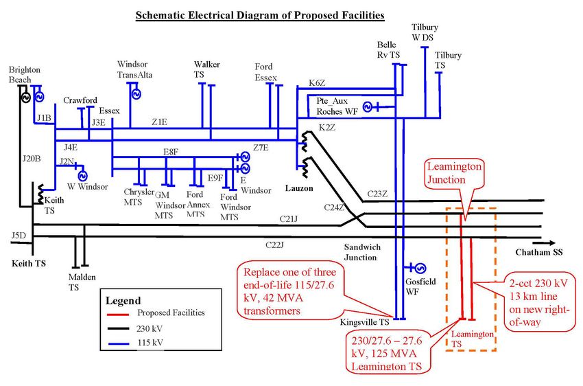
subsystem restoration need and the Kingsville – Leamington capacity need. As illustrated in Figure 7-1
the project consists of the installation of a new 230 kV supplied transformer station near Leamington
connected to the existing C21J/C22J circuits via a new 13 km double-circuit 230 kV connection line on a
new right-of-way.
The total cost of this project is $96.7M made up of:
(a) Build 230/27.6 – 27.6 kV 75/100/125 MVA Leamington TS with six LV breaker positions,
plus other required switchgear: $32.1M
(b) Build a 13 km 2-circuit 230 kV line on a new right-of-way tapping into existing 230 kV
circuits C21J/C22J plus Optical Ground Wire: $45.3M.
(c) Carry out distribution work for Leamington TS: $19.3M. Other additional distribution work
includes two additional feeder positions at Leamington TS, and protection upgrades for in-
service Kingsville DG transferred to Leamington TS.
With the establishment of Leamington TS, load will be transferred from Kingsville TS to the new station,
such that the Kingsville TS load will be reduced to about 50 MW. As discussed in the IRRP report, this
presents an opportunity to downsize the station from four transformers to two transformers, and would
result in a combined supply capability in the Kingsville-Leamington area of 210 MW.
Figure 7-2 is a preliminary plan for the transfer of Kingsville TS feeders to Leamington TS. Feeders
which are shown in blue will be completely transferred to Leamington TS, and the ones shown in green
will be partially transferred to Leamington TS.
7.1.2 Recommended Plan and Current Status
Hydro One filed an application on January 22, 2014 with the OEB under Section 92 of the OEB Act for
an order granting leave to construct approximately 13 km of new 230 kV transmission lines on steel
lattice towers on a new right of way in the Windsor-Essex area and the installation of optic ground wire
for system telecommunication purposes on existing C21J/C23Z towers near Leamington Junction and on
new 230 kV towers. The application included a request for OEB approval of the methodology for
31Windsor-Essex – Regional Infrastructure Plan December 22, 2015
allocating project cost to Hydro One Distribution, embedded LDCs and Sub-Transmission class
customers.
On February 12, 2015, Hydro One filed an updated application that included the new 230/27.6 kV
Leamington Transformer Station (Leamington TS). The OEB decided that the proceeding would be
addressed in two phases. Phase 1 would only deal with the leave to construct application and Phase 2 of
the proceeding would deal with cost allocation. Phase 1 of the SECTR S.92 proceeding has concluded and
the "Leave to Construct" approval was granted by the OEB on July 16, 2015. The expected in-service
date for the SECTR Project is June 2018. Phase 2 of the proceeding is continuing via an OEB policy
review rather than the originally planned adjudicative process.
32Windsor-Essex – Regional Infrastructure Plan December 22, 2015
Figure 7-1 Schematic Electrical Diagram of the Proposed Facilities
33W
Windsor-Essex – Reg
gional Infrastructure Plan December 22,, 2015
Figure 7-2 Preliminary Distrribution Feeder Pllans for SECTR P
Project
34Windsor-Essex – Regional Infrastructure Plan December 22, 2015
7.2 Keith TS End-of-Life Auto-Transformer Replacement
7.2.1 Description
Keith TS is equipped with 2-230/115 kV 115 MVA autotransformers. These autotransformers are 1950’s
vintage and near end-of-life and require replacement.
7.2.2 Recommended Plan and Current Status
Due to SECTR project additional capacity will not be required and the end-of-life autotransformers at
Keith TS will be replaced with equivalent like-for-like 125 MVA units. The expected in-service date is
2020. There are no cost implications for the LDCs.
7.3 Kingsville TS End-of-Life Transformer Replacement
7.3.1 Description
Kingsville TS is equipped with 4-115/27.6 kV 25/33/42 MVA transformers. One of these transformers
was recently replaced, but the other three are 1950’s vintage and will require replacement in the near
future.
Due to SECTR project and the associated reduction in load at Kingsville TS, the station may be
downsized and reconfigured as a two-transformer station. Hydro One Distribution is further reassessing to
justify retaining the four-transformer arrangement if they receive additional request for connections at
Kingsville area.
7.3.2 Recommended Plan
Hydro One Distribution to complete their connection capacity assessment as part of distribution system
planning before Q3 2016 so that replacement and reconfiguration plan can be finalized by Hydro One in a
timely manner.
7.4 Gordie Howe International Bridge (GHIB)
7.4.1 Description
The Gordie Howe International Bridge (GHIB) is a construction project under a bi-lateral agreement
between the federal governments of Canada and the USA, and the governments of Ontario and Michigan,
to construct a new border crossing between Windsor and Detroit. It will comprise a 12 km westerly
extension of Hwy 401 to a site near Keith Transformer Station, where a new customs plaza and a new
bridge over the Detroit River will be constructed. The highway will be extended by the Ministry of
Transportation of Ontario (MTO), while the customs plaza and the bridge will be constructed by
Transport Canada.
35Windsor-Esssex – Regional Infrastructure
I Pllan December 222, 2015
The GHIB B project is multi-faceted
m in
i its impacts on Hydro Onne facilities annd operationss at Keith TS
including: transmission n lines, fiber lines
l and feed
ders relocationn; insulation contaminatioon due to salt spray
om new bridg
effects fro ge; relocation of access rou utes; possible security issuees for staff acccessing and
working ata the station; impacts on existing utilitiees (water/sewwer/gas). In adddition, the GGHIB project w will
reduce thee footprint off the station annd encumber egress from tthe station. Coonsequently, this project w will
impact futture expansio on work at thee station and possibly
p limitt the extent too which the sttation can be
developed d relative to itts ultimate plaan developmeent over the loong term.
7.4.2 Recommende
R d Plan and Current
C Statu
us
o mitigate theese impacts, as
In order to i Figure 7-3 below, additiional real estaate is requiredd for
a illustrated in
future exppansion to thee north of McKKee Rd. The existing transsmission liness and feeders will also neeed to
egress thee station via underground
u cables
c so as not to interferee with the briddge operationns.
The cost of
o this projectt will be fully
y recovered from the Winddsor Detroit BBridge Authorrity (WDBA).. A
Transmisssion Assets Modification
M Agreement
A (T
TAMA) with tthe WDBA iss expected to be finalized bby
early Januuary 2016. Appprovals for executing
e the project are exxpected by M
March 2016 foor a planned inn-
service daate by the end
d of 2018.
Figure 7-3 Gordie Howe In
nternational B
Bridge (GHIB
B) Project
36Windsor-Essex – Regional Infrastructure Plan December 22, 2015
8. OTHER PROJECTS
There are other wires projects that are currently under development and pending decision in the Windsor-
Essex Region. These projects are local in nature and being planned and developed by Hydro One and
relevant LDC as discussed below.
8.1 Malden TS Additional Feeder Positions
8.1.1 Description
Due to the load increase that’s expected from the planned Detroit River International Crossing work and
local highway construction, Essex Power has identified a need for two additional 28 kV feeder positions
to be constructed at Malden TS.
The Malden transformer station is currently equipped with two 75/125 MVA transformers, 12 feeder
positions and two capacitor banks and this plan involves expanding the station to 14 feeders. The two
transformers at Malden TS were recently replaced, and there is additional capacity available at the station
to meet the load requirement of the customer.
Based on a preliminary estimate the following will be the cost for the different layouts:
Installation of two 28kV feeder breaker positions with feeder tie with underground feeder egress
to outside station fence by 1 meter. Estimated cost of about $1.1M
Installation of one 28kV feeder breaker position with no feeder tie with underground feeder
egress to outside station fence by 1 meter. Estimated cost of about $875k
Installation of one 28kV feeder breaker position with a break before make connection to alternate
bus with underground feeder egress to outside station fence by 1 meter. Estimated cost of about
$925k
8.1.2 Recommended Plan and/or Current Status
The above options have been provided to Essex Powerlines Corp. Hydro One is awaiting its decision on
the preferred option expected to be made in 2016.
8.2 Tilbury TS Transformer End-of-Life Replacement
8.2.1 Description
Tilbury West HVDS and Tilbury TS are both supplied from 115 kV circuit K2Z and are adjacent to each
other. The two stations supply the Town of Tilbury and surrounding area. Tilbury West HVDS consists of
2 x 15/20/25 MVA, 115/27.6 kV transformers of 1980’s vintage with two feeder positions; and Tilbury
TS consists of 1 x 6/8 MVA 115/27.6 kV transformer of 1950’s vintage with one feeder position. The
37Windsor-Essex – Regional Infrastructure Plan December 22, 2015
2014 peak load at Tilbury TS was 1.0 MW, and 16 MW at Tilbury West HVDS. The future load levels
over the next 10 years at these stations are not expected to grow significantly.
Tilbury TS is near its end-of-life, and a decision to replace or retire should be made by 2017. Following
three options are under consideration for Tilbury TS:
(1) Transfer Tilbury TS load (M1 feeder) to Tilbury West DS and decommission Tilbury TS
at a cost of about $1.7M. This option is feasible as there is sufficient capacity at Tilbury
West HVDS to accommodate both the Tilbury West HVDS forecast load and the Tilbury
TS forecast load into the long term. Further, Tilbury West HVDS has sufficient capacity to
accommodate its existing DG connections plus the existing 5 MW solar DG currently
connected to Tilbury TS.
(2) Refurbish Tilbury TS at a cost of about $5M. This option would retain the supply capacity
level and supply diversity that currently exists.
(3) Build a new DESN station at Tilbury TS with dual 115kV circuit supply from the K2Z and
K6Z for an expected cost of about $20M. This would include building the 115kV line out
from Tilbury Junction to the TS and a complete new station.
8.2.2 Recommended Plan and Current Status
Option 1 is the least cost alternative. It is recommended that Hydro One will have further discussions with
the LDCs regarding these options and associated costs. These discussions are expected in 2016, and a
decision is expected to be made by no later than 2017. Project construction is planned to commence in
2018 for an expected in-service in 2019. Depending on the option selected, costs may have to be
recovered from the LDCs consistent with the TSC.
8.3 Keith TS T1 Transformer End-of-Life Replacement
8.3.1 Description
Keith TS transformer T1 (25/33/42 MVA 115/27.6 kV) is of 1950’s vintage and it is approaching end-of-
life. EnWin is the only LDC supplied from this Keith T1 and exclusively serves a single customer
Nemak. The peak load was 8 MW in 2014. The load growth is expected to remain at this level in the
long-term.
There is sufficient capacity at the Keith DESN station to accommodate both the forecast at Keith DESN
load plus the forecast Keith TS T1 load over the next 10 years.
Following three possible options are considered to address the end-of life issue for Keith TS T1:
(1) Replace Keith TS T1.
(2) Transfer Keith TS T1 load to Keith T22/T23 DESN station.
(3) Resupply Nemak from another EnWin feeder connected to Keith T22/T23 DESN.
38Windsor-Essex – Regional Infrastructure Plan December 22, 2015
8.3.2 Recommended Plan and Current Status
It is recommended to develop cost estimates for each of the option. Following that Hydro One will initiate
discussions with EnWin to review the options and decide on a preferred option.
Cost estimates are expected in Q1 of 2016 and selection of a preferred option is expected before the end
of 2016. Discussions will then ensue with Hydro One and EnWin regarding planned construction dates.
39Windsor-Essex – Regional Infrastructure Plan December 22, 2015
9. CONCLUSION
THIS REGIONAL INFRASTRUCTURE PLAN REPORT CONCLUDES THE
REGIONAL PLANNING PROCESS FOR THE WINDSOR-ESSEX REGION.
THIS REPORT MEETS THE INTENT OF THE PROCESS DESCRIBED IN
SECTION 2 WHICH IS ENDORSED BY THE OEB AND MANDATED IN THE
TSC AND DSC.
This RIP report provides a single consolidated source of information for infrastructure plans in the
Windsor-Essex Region. It develops and outlines a plan for investments in transmission and/or distribution
facilities to meet the electricity needs within the region. The RIP report was developed in collaboration of
a Technical Working Group consisting of representation from the LDCs in the region, the IESO, and led
by Hydro One consistent with the requirements set out in the TSC, DSC and the PPWG report.
This report highlights several near-term needs in the region for which implementation plans have already
been developed and are planned for completion in the next five years. Table 9-1 provides a status of these
projects along with their cost and timelines. Projects requiring further planning on scoping and pending
decisions on the preferred alternative are provided in Table 9-2. Over the next five years, the total
transmission and distribution investments associated with these projects is approximately $215M -
$225M.
Table 9-1 Project Under Development
Project/Plan Cost I/S Performed by
Supply to Essex County Transmission
$77.4 Million March 2018 Hydro One
Reinforcement “SECTR TX”
Supply to Essex County Transmission March 2018
$19.3 Million Hydro One Distribution
Reinforcement “SECTR DX” (first stage)
Replacement of Keith end-of-life 2020
$45 Million Hydro One
autotransformers
Replacement of Kingsville end-of-life
$12 Million 2018 Hydro One
transformers
230kV/115kV circuit and 27.6kV
feeder reconfiguration at Keith TS due
$63 Million October 2018 Hydro One
to Gordie Howe International Bridge
(GHIB) Project
Transformer replacement and station
$8.46 Million December 2016 Hydro One
refurbishment at Crawford TS
40You can also read