Robopheus: A Virtual-Physical Interactive Mobile Robotic Testbed
←
→
Page content transcription
If your browser does not render page correctly, please read the page content below
Robopheus: A Virtual-Physical Interactive Mobile Robotic Testbed
                                                                   Xuda Ding1 , Han Wang2 , Hongbo Li3 , Hao Jiang1 and Jianping He1

                                           Abstract— The mobile robotic testbed is an essential and
                                        critical support to verify the effectiveness of mobile robotics
                                        research. This paper introduces a novel multi-robot testbed,
                                        named Robopheus, which exploits the ideas of virtual-physical
                                        modeling in digital-twin. Unlike most existing testbeds, the
                                        developed Robopheus constructs a bridge that connects the
                                        traditional physical hardware and virtual simulation testbeds,
arXiv:2103.04391v1 [cs.RO] 7 Mar 2021

                                        providing scalable, interactive, and high-fidelity simulations-
                                        tests on both sides. Another salient feature of the Robopheus
                                        is that it enables a new form to learn the actual models from
                                        the physical environment dynamically and is compatible with
                                        heterogeneous robot chassis and controllers. In turn, the virtual
                                        world’s learned models are further leveraged to approximate
                                        the robot dynamics online on the physical side. Extensive
                                        experiments demonstrate the extraordinary performance of the
                                        Robopheus. Significantly, the physical-virtual interaction design
                                        increases the trajectory accuracy of a real robot by 300%,                            Fig. 1: The architecture of Robopheus
                                        compared with that of not using the interaction.

                                                              I. INTRODUCTION
                                           The study of mobile robotics has received considerable                  various scenarios due to the limited space and resources.
                                        attention in the last decade and has been deployed in numer-               Besides, the robots provided by the physical testbed may
                                        ous industrial and military applications. Fruitful tools have              not meet the need of various control strategies, due to the
                                        been adopted to develop the research, such as distributed                  fixed robot kinetics type.
                                        control [1], [2], learning [3], [4] and information theories                  This paper presents a novel testbed that combines the
                                        [5]. Specifically, due to the rapid development of computer                merits of both traditional virtual testbed and the physical
                                        and mechatronics technologies, mobile robotic testbeds have                testbed and even beyond can be achieved. On the one hand,
                                        emerged as a critical part of the research cycle to validate               the state of art digital-twin idea provides the potential for
                                        the theoretical results and protocols [6]–[14].                            virtual testbeds to perform high-fidelity simulations based
                                           Generally, testbeds can be divided into two categories:                 on accurate digital models of physical objects [17], [18]. On
                                        virtual and physical. The virtual testbed enjoys customized                the other hand, some prior works have shown the possibility
                                        experiment fashion, convenient maintenance, and flexible                   to identify the internal system structure and parameters from
                                        scalability, applying well to the illustration of various the-             accessible data [19]–[21]. However, the real-time interaction
                                        oretical validation [6]–[8], [15], [16]. The major drawback                between the physical and virtual worlds is blocked, and
                                        is that the real world’s typical implementation issues are                 the two parts run independently. Besides, it is tough to
                                        usually simplified or even omitted in the virtual environment              construct heterogeneous object models that consider the
                                        (e.g., wheel slip, friction, computation time, and actuator                practical factors (e.g., wheel slip and friction).
                                        constraints), failing to fulfill a high-fidelity requirement.                 Therefore, we aim to build a new physical-virtual interac-
                                        On the contrary, the physical testbed provides a way to                    tion based mobile robotic testbed, named Robopheus, which
                                        practically validate the proposed theories’ effectiveness, help            provides high-fidelity simulations in the virtual world and
                                        improve the theory inadequacy, and discover new issues in                  high-accuracy tests in physical environments. The physical
                                        real implementation [9]–[13]. A representative example is                  part includes our self-designed heterogeneous robots and
                                        Robotarium [12], [13], which provides worldwide remote                     supports the real-time model construction and calibration in
                                        access for researchers to use the testbed for experiments.                 the virtual part. The virtual part provides extensive simula-
                                        Nevertheless, physical testbeds are challenging to apply for               tion settings and high-fidelity objective models, including the
                                                                                                                   accessed environments and heterogeneous robots to all users.
                                          1 The authors are with Department of Automation, Shanghai Jiao
                                                                                                                   The testbed is compatible with heterogeneous kinematics
                                        Tong University, Shanghai, 200240, China. E-mails: {dingxuda,
                                        mouse826612011, jphe}@sjtu.edu.cn                                          robots and controllers, and users can install the virtual testbed
                                           2 Han Wang is with the Department of Engineering Science, University
                                                                                                                   on their computers. Specifically, the robot and environment
                                        of Oxford, Oxford, UK. E-mail: han.wang@linacre.ox.ac.uk                   models can be learned from the robot state evolution in
                                           3 Hongbo Li is with the Pillar of Engineering Systems and Design,
                                        Singapore University of Technology and Design, Singapore 487372. E-mail:   the physical testbed. Furthermore, the online learned models
                                        hongbo li@mymail.sutd.edu.sg                                               in the virtual environment can be used for predicting the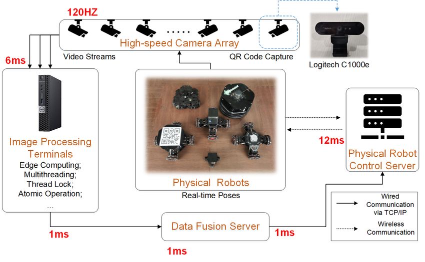
future states of robots, providing an optimal strategy for
actual control in physical testbed. The architecture of the
Robopheus is shown in Fig. 1).
   The achieve the Robopheus, the main challenges lie in
three aspects. i) Due to the variety of heterogeneous kine-
matics robot chassis and the plug and play controller design.
It is challenging to construct a unified connector that is
compatible with heterogeneous robots. ii) The environment
factors such as wheel slip, friction, and actuator constraints
are not prior knowledge in the virtual world, making it hard
to construct the model structure and high-fidelity. iii) As                    Fig. 2: The structure of Robopheus
the Robopheus is combined with various small and coupled
systems (e.g., positioning system, robot-embedded control
system, and communication systems), the global stability of        executions and localization sub-system (details in Section
robot control remains unsolved. Our work overcame these            III.A) for robot pose detection. Real time data is aggregated
challenges, and the contributions are as follows.                  into the in-memory database before being transferred into
                                                                   disk database, for ensuring low latency communication and
   • To the best of our knowledge, it is the first time to
                                                                   independent operation of each part.
     develop an interactive virtual-physical mobile robotic
     testbed. The constructed bridge of two sides overcomes           In the system, the Physical control server communicates
     the disadvantages of a single physical or virtual testbed     with robots via wireless protocol (e.g., ZigBee, Digimesh,
     and provides a newly interactive-learning form to en-         and WIFI), controls robot movements, and requests robot
     hance the real-time task performance of actual robots.        states. The data is transferred into the in-memory database
   • We self-design heterogeneous kinematics robot chassis
                                                                   via wired TCP/IP protocol. The virtual simulation server is
     and controllers, along with their unified connector. The      with virtual control and simulation components and performs
     design covers more application scenarios and require-         a virtual testbed. The control component is a digital twin of
     ments for algorithm verification, thus improves the           the physical robot control server, built by Python, releases
     scalability and accessibility of the physical testbed.        topics to provide control strategies, and requests robot states
   • We propose a real-time method to learn the practical
                                                                   in the simulation component. Topics are written in the form
     dynamic models of robots from the real operation              of standard Gazebo statement, for the simulation component
     data, considering wheel slip, friction, and actuator con-     is built in Gazebo. The simulation component accomplishes
     straints. The online learned models provide real-time         robot simulations in a virtual environment, such as robot
     feedback to improve the high-fidelity of the virtual          formations, obstacle avoidance, and robot collaborations. The
     simulation and can be utilized for motion predictions.        data produced by the virtual simulation server is transferred
                                                                   into the in-memory database directly via wired TCP/IP
   The remainder of this paper is organized as follows.
                                                                   protocol. The learning server uses data of virtual and physical
Section II gives descriptions of physical-virtual digital-twin
                                                                   testbeds from the in-memory database and learns information
testbed system. Section III provides the design of the phys-
                                                                   such as robot dynamics models and interaction rules. The
ical testbed and details of the heterogeneous kinematics
                                                                   output data of the server is back to the in-memory database.
robot chassis, controllers, and the connector. Section IV
                                                                   Servers are deployed into different operating systems (OS),
provides the design of the virtual testbed and details of
                                                                   such as the Robot Operating System (ROS) under UBUNTU
models. Section V shows the physical-virtual testbed and
                                                                   16.04 and Windows 10 OS. For operational convenience, we
the learning procedure and effect of the physical-virtual
                                                                   choose VMware ESXi 7.0 for server management [22]. The
interaction. Lastly, conclusions are given in section VI.
                                                                   virtual switch in ESXi is on the trunk mode.
              II. ROBOPHEUS OVERVIEW
                                                                             III. PHYSICAL TESTBED DESIGN
   The Robopheus is constituted by physical testbed, virtual
testbed, and learning procedure (see Fig. 1). Currently, the in-     This section gives details of the physical part of
teraction between physical and virtual testbeds is the kinetics    Robopheust, including localization and control subsystem
data and model parameters. Models of physical and virtual          design, heterogeneous robots and controllers design, and
testbed generate data separately, and the data interaction         robot control method.
triggers the model learning procedure and drive the virtual
model to approximate the actual physical model. Based on           A. Localization and Control Subsystem
the above mechanism, the Robopheus provides high fidelity,           To detect poses of robots, a high-speed camera array with
high utilization, and generalization rate for robot simulations,   a 120 Hz frequency is installed under the roof. The array
which will be demonstrated in the experimental part.               can cover a large-scale area of the physical testbed and
   The Robopheus is constituted by virtual simulation sever,       can be expanded. The top of the robot has a quick-respond
learning server and physical robot control server (see Fig.        (QR) code picture with identity information. The cameras
2). Besides servers, system has physical robots for task           capture QR codes to identify robots and their positions,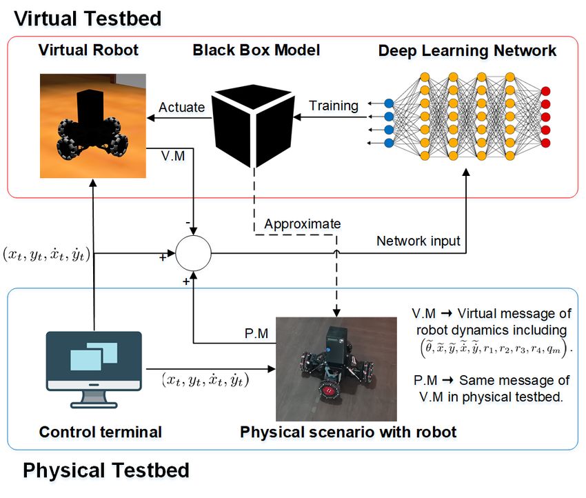
TABLE I: Actuators and numbers of pins of different drive
methods for heterogeneous robots
Drive method Omni-directional 2DD 4DD
Actuators 4 motors 2 motors 4 motors
Number of pins 28 14 28
Drive method FWD RWD 4WD
2 motors 2 motors 4 motors
Actuators
1 steering gear 1 steering gear 1 steering gear
Number of pins 17 17 31
Fig. 3: Localization and control subsystem structure
different drive methods and controllers with 3 different
processors are designed. Further, a unified connector for
directions. Further, velocities are estimated based on two robot chassis and controllers is developed (shown in Fig. 4),
adjacent samples and sampling intervals. which provides an easy way to install or uninstall controllers
The 120 Hz video streams with images of 640 × 480 on robots, since the connector is designed to be fool-proofing.
pixels (Logi C1000e [23]), are processed by image process-
ing terminals (OptiPlex 7070 Micro Desktop [24]). Lens A small Omni-directional robot chassis with 4 Omni
distortion correction is the first step of the processing, wheels is developed in Fig. 4 (350 mm length, 350mm
based on camera calibration model parameters. Then, image- width, and 300 mm height). 4 brushless geared motors
enhancing procedure (e.g., optical flow, motion segmenta- with a maximum power of 176 W are installed to drive
tion, and tracking). Finally, the positions and angles of QR the robot and carry more peripherals (up to 7 Kg). 4
codes are detected. To guarantee the processing speed, each independent suspension systems are designed to keep wheels
terminal calculates the stream of one camera under multi- on the floor all the time and guarantee the Omni-directional
thread mode. This edge-computing embedded method keeps movement’s stability. Further, the robot can also achieve 2-
the computational time below 6 ms. Operations in processing wheel differential drive by setting 2 wheels into a passive
programs, such as thread locks and atomic operations, ensure mode (i.e., with no power supply). 4 more types of robot
the information following the first-in-first-out rule. Data chassis are also designed, as the front-wheel-drive (FWD),
fusion server collects data from all terminals with 1 ms rear-wheel-drive (RWD), four-wheel-drive (4WD), and 2 ×
communication latency, converts the positions and angles of 2 differential drive. The actuators and numbers of each type
each camera coordinate to information of unified coordinate. of chassis’s pins are listed in Tab. I1 . As for controllers, 8-
Then, robot control algorithms, such as consensus al- bit (ATmega 2560), 32-bit (ATSAM 3X), and Nvidia Jetson
gorithm [25], leader-follower control [26] and leaderless TX2 are used as processors to meet different computing
control [27], [28], can be uploaded into physical robot control needs. 8-bit processors can achieve simple centralized con-
server. The server calculates the command output (e.g., target trol tasks, such as formation transforming, tracking, and
position and speed) and broadcasts the output to robots via covering. 32-bit processors with localization devices, such
wireless communication. In the meantime, the robot can as ultra-wideband positioning, lidar, and global navigation
send the message, such as encoder, inertial measurement satellite system (GNSS), can achieve self-localization and
unit (IMU), and magnetic-sensor feedback, back to the distributed control tasks. Nvidia Jetson TX2 enables robots
server. The message is used to achieve delicate control or with powerful computational ability to realize intelligent self-
data storage for further research. The one-way transmission control tasks with peripherals (e.g., depth cameras, lidar, and
latency of wireless communication is no more than 12 ms real-time kinematic based GNSS).
based on a hexadecimal short coding method. Overall, the Based on the number of pins in Tab. I, we designed a
control latency from QR code capture to robot execution is 38-pin unified connector for robot chassis and controller
about 21 ms. Therefore, the total latency is about 25 ms with connection (see in Fig. 4). 4 pins are used for battery power
our computing and transmission resources. The sampling supply and charging. 31 pins are used for 4 motors and
frequency is 120 HZ, which is enough for accurate low- 1 steering gear, which can meet all requirements for all
speed, e.g., 2 cm/s, robot control (less than 1 % error). drive methods in Tab. I. The connector firmly links chassis
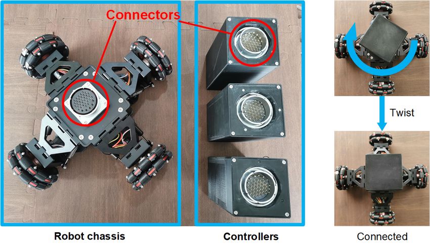
B. Heterogeneous Robots and Controllers and controller by a 60-degree twist, which is convenient for
changing the chassis-controller pair.
To cover more application scenarios and requirements
for algorithm verification, heterogeneous robots with various 1 Each motor has 3 pins for driven power, 4 pins for feedback commu-
chassis and controllers that meet different performance are nication. Each steering gear has 2 pins for driven power, 1 pin for control
necessary. Currently, heterogeneous robot chassis with 6 signal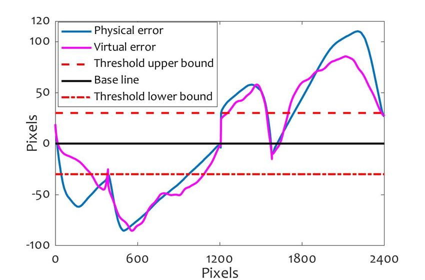
Fig. 4: Connectors and install illustration                               Fig. 5: Robot control architecture

C. ROBOT CONTROL METHOD                                               A. 3D model
   Heterogeneous robots usually have different chassis and                We build our virtual testbed on physical engine simulation
drive methods. In this subsection, we briefly introduce the           software Gazebo to realize high extensibility scenarios and
robot control method for the Omni-directional robot as an             high fidelity models of the real world. Gazebo integrated the
example (see in Fig. 5). The rest robots have a difference            ODE physics engine, OpenGL rendering, and support code
in dynamics, but their control architectures are the same.            for sensor simulation and actuator control. The virtual robot
Our proposed control architecture consists of three main              is constructed accurately according to the real one, which
components: i) a command fusion estimator which gives the             means that the materials, size, weight are all the same. In
command to motors based on estimated orientation, position,           addition, we can also simulate many real-world elements that
and velocity of the robot; ii) a dynamic-level control which          will influence robots’ motion, e.g., ground friction, gravity,
gives the command to motors based on estimated velocity               surface contact.
and acceleration of the robot; iii) a motor control which                 To establish a close loop between the virtual and real
drives the robot based on commands. Together, they achieve            systems, we have to build every part of the virtual model
a stable movement of the robot by coordinating the control            similar to the real one. Unlike existing work on gazebo
of various actuators.                                                 simulation [29], we not only one-to-one duplicate our robot
   Specifically, accelerations at Cartesian coordinates               mold on Gazebo, but also simulate the robot dynamic on
(ẍ, ÿ, z̈), angle and angular velocity (θ, (θ̇)),are measured       it. The relationship among parts of the virtual structure can
by inertial measurement unit (IMU) and magnetic sensor                be found in Fig. 6. The component of robot mold has three
(M-sensor) on the controller, respectively. The rotational            main parts: roller, wheel, and base link. These three parts are
speed of each wheel (r1 , r2 , r3 , r4 ) is measured by encoder       connected by a virtual connector called a joint.
which is integrated in the motor, sent to the controller via              The control input of the system include four parts, related
unified connector. Robot position and velocity estimator              to four joint linked base link and four wheels. In Gazebo,
calculates estimated position of the robot (x̃, ỹ, ẋ,       ˜ ẏ)
                                                                ˜     they are realized through the topic publisher. The first part
based on the feedback of IMU, M-sensor and encoder.                   of the system model is the motor driver, which will convert
Orientation estimator calculates the estimated angle (θ̃)             the input control signal to torque. Next, torque will drive the
                           ˜                                          joint to rotate together with the wheel against ground friction.
and angular velocity (θ̇) based on the feedback of IMU
and M-sensor. The input commands include target position              The output of the system is robot velocity and acceleration,
(xt , yt ) and target speed (ẋt , ẏt ). Command fusion estimator
gives command (qic ) to ith motor control and estimated
moving states to dynamic-level control at the same time.
Dynamic-level control uses the rotational speeds of wheels
and estimated moving states to give command (qid ) to
ith motor control based on structure and dynamic of the
robot. The main algorithm in motor control is proportional
integral derivative (PID). The current of ith motor (qim ) is
considered as feedback of PID controller. Finally, motor
controls drive the robot.

            IV. VIRTUAL TESTBED DESIGN
   This section shows the virtual structure of Robopheus,
including the simulation environment, components of robot
mold, and system model of the whole virtual testbed.                           Fig. 6: Virtual testbed structure on Gazebo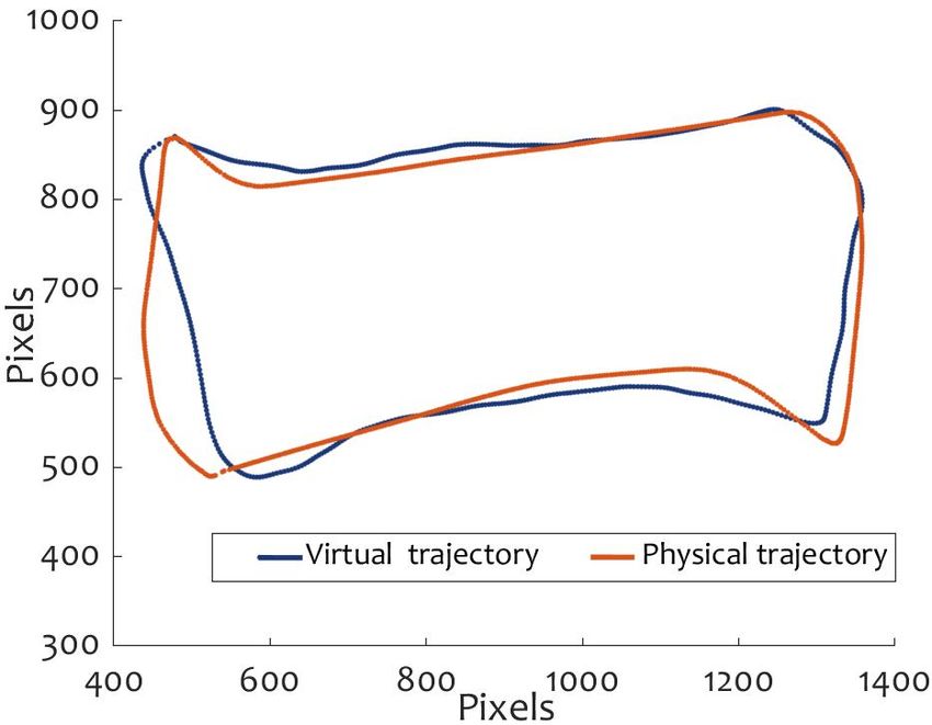
(a) trajectory in physical part       (b) trajectory in virtual part

                                                                   (c) trajectory error in physical part   (d) trajectory error in virtual part

       Fig. 7: Dynamics model learning architecture               Fig. 8: Experimental results for physical and virtual testbed
                                                                  respectively without interaction
which are both three dimensional.
                                                                  to improve the real performance.
B. Dynamics Model Learning
                                                                             V. EXPERIMENT EVALUATION ON
   In this part, we implemented an online revision of the
                                                                               VIRTUAL-PHYSICAL TESTBED
Robopheus virtual model to continuously approach the dy-
namics of the robot in the real physical scene during the            In this section, we implement comparative experiments
operation. Although we have built every detail of the robot       on the physical testbed and virtual testbed, respectively, to
in a virtual environment, it is hard to get the dynamics          further illustrate the effectiveness of the Robopheus. The
of the robot for the complexity of the physical process.          experiment consists of three parts: i) experiment on physical
There are inevitably some differences between the virtual         testbed without optimization from virtual testbed, on the
model and the physical robot, e.g., motor parameters. It is       other side the virtual testbed also gets no information from
also vital to consider the impact of ground material and the      physical testbed to modify the model; ii) virtual testbed
accompanying phenomena (e.g., friction and slipping) on the       utilizes data from physical testbed, and then compute dy-
robot dynamics in different physical scenarios. Specific to the   namics model learning process mentioned in section IV,
above problem and realizing a close loop between physical-        subsection B to train the black-box model of virtual testbed;
virtual testbed, designing a real-time model learning method      iii) in addition to the last experiment, compute the online
from the physical scenario to the virtual model is necessary.     supervising process to optimize the control protocol for the
   Modern deep learning methods give an excellent solution        physical testbed.
to this question [30]. We collect the input and output data          To show the utility of Robopheus, we choose the most
for the dynamic model learning process. Details of this           basic as well as the typical task of the mobile robot, path
process can be seen in Fig. 2, the learning server will get       planning. We set four targets for the robots, which are located
states input and calculate model, then transmit to the in-        on the four corners of a rectangle. Robots are desired to move
memory database. In the specific implementation, shown in         precisely according to the desired trajectory towards the
Fig. 7, we construct the robot model constrained by the           target. Unfortunately, this seemingly ”simple” task is always
physical environment as a black-box model and obtain the          hard to realize because of different noises in the physical
robot dynamic parameters of the physical testbed in real-time     environment, including ground friction, wheel slipping, and
during the operation. The black-box model is continuously         so on. The control protocol used in the experiment is the
approached to the robot dynamics in the physical testbed          widely used PID control, which is shown as follow
through the deep learning network. Finally, a high degree of
                                                                               x(k + 1) = x(k) + εp (xtarget − x(k)),                         (1)
fit between the virtual model and the actual physical model
is achieved.                                                      where x(k) denotes the position of robot at time k, εp is the
   Through the above mechanism, the Robopheus can mod-            coefficient of p-controller, xtarget is position of targets.
ify the virtual model online during the physical testbed
operation, so that the virtual testbed realize a high-fidelity    A. Experiment A
simulation of the actual scene (e.g., considering friction           In the first part, we show the results of the experiment on
and slip). Then, using the revised model, we can make the         the physical testbed and virtual testbed without interaction.
optimization on the control strategy for the physical testbed     The target positions on the physical testbed are set to [(500,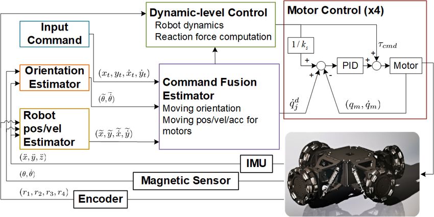
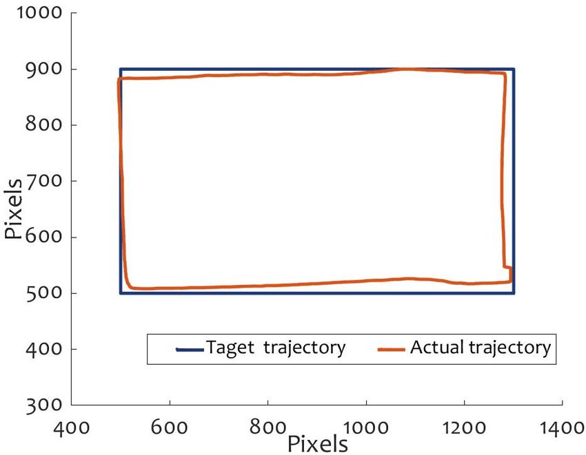
(a) P-V trajectories         (b) P-V trajectory errors
                                                                        (a) trajectory in first round     (b) trajectory in second round
Fig. 9: Experimental results for physical and virtual testbed
with learnt model

500) - (500, 900) - (1300, 900) - (500, 900) - (500, 500)],
on the virtual testbed are set to [(500, 500) - (500, 900) -
(1300, 900) - (500, 900) - (500, 500)] (the unit is pixel, and       (c) trajectory error in first round (d) trajectory error in second round
1 pixel is about 2.5 mm). We also set a threshold of ±30
pixels allowable position deviation. The trajectory results of     Fig. 10: Experimental results for physical testbed with fully
experiment are shown in Fig. 8 (a) and Fig. 8 (b). It should       P-V interaction
be noted that the actual trajectories are computed by real
position data from physical testbed and virtual testbed. The       of experiment are shown in Fig. 10 (a) and Fig. 10 (b). The
trajectory errors are shown in Fig. 8 (c) and Fig. 8 (d). It       trajectory errors are shown in Fig. 10 (c) and Fig. 10 (d).
can be seen that due to the slip and friction in physical and         It can be seen that the physical testbed gets a much
virtual testbeds, the actual trajectories have deviations from     better trajectory compared with the last two experiments.
the target trajectories. The maximum errors exceed 91 pixels       The actual trajectories are close to the target. The error
and 120 pixels in physical and virtual testbeds, respectively.     stays in the threshold range all the time. Compared with
Also, there exists a huge gap between the physical and             Experiment A, the trajectory accuracy of robot movement
virtual testbeds. The difference in slip and friction causes a     improves about 300% with the feedback of the physical and
difference in the dynamic models of the robot in two testbeds.     virtual interaction. The virtual testbed predicts the robot’s
Therefore, it is important to learning a dynamic model from        movement in the physical testbed based on the learned model
the physical testbed, and mimic the robot movement in the          and further guides the robot to move better.
virtual testbed, to construct a high-fidelity simulation.
                                                                                           VI. CONCLUSION
B. Experiment B
                                                                      In this paper, we developed a novel virtual-physical inter-
   The second part shows the experimental results on the           active mobile robotics testbed, which is named Robopheus.
physical and virtual testbed with part interaction, based on       The system is compatible with heterogeneous kinematics
the data from physical testbed to virtual testbed to compute       robots and various control algorithms, providing a reliable
dynamics model learning process for the virtual model. The         verification environment for theory research. The operation
target position and the threshold remain the same. The results     data during physical experiments are further utilized for
are shown in Fig. 9 (a) and Fig. 9 (b), respectively.              the dynamics model learning process. The Robopheus can
   It is observed that after the training process, these two       be run in physical, virtual, and physical-virtual interactive
trajectories and error curves are close to each other, which       forms independently. The physical form provides a ver-
means that the virtual model is similar to the physical model      ification environment for heterogeneous kinematics robot
by introducing the learning procedure. The influence of slip       control algorithms. Furthermore, the operation data during
and friction in the physical testbed can be introduced to the      the experiment can be stored in a database for the dynamics
virtual testbed based on the procedure.                            model learning process. The virtual form is operated based
                                                                   on the virtual models to perform high-fidelity simulation,
C. Experiment C                                                    which can be installed in computers and used anytime. The
   We show the experimental results on the physical testbed        physical-virtual form provides the dynamics model learning
and virtual testbed with full interaction in the last part.        process for the virtual model and online optimization of the
In addition to the virtual testbed training model, we also         physical testbed controller.
utilize the online training process for the physical controller.      The system can be used in various robotics applications,
The virtual testbed can compute the optimal feedback for           e.g., robot swarm, SLAM, heterogeneous robot cooperation.
the physical testbed control. The target position and the          Users can easily construct these scenes in a virtual testbed
threshold remain the same. Two repeat experiments are              before experimenting on physical ones. Also, the virtual-
conducted to show the effectiveness of the P-V interaction         physical interaction can help with optimizing the perfor-
for control performance improvement. The trajectory results        mance of those applications.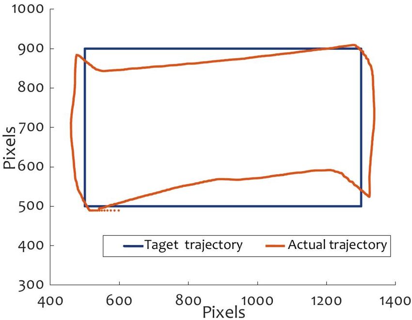
R EFERENCES                                               IEEE/RSJ International Conference on Intelligent Robots and Systems
                                                                                       (IROS), pp. 3709–3714, IEEE, 2018.
 [1] D. V. Dimarogonas, E. Frazzoli, and K. H. Johansson, “Distributed          [15]   V. Vladareanu, R. I. Munteanu, A. Mumtaz, F. Smarandache, and
     event-triggered control for multi-agent systems,” IEEE Transactions               L. Vladareanu, “The optimization of intelligent control interfaces
     on Automatic Control, vol. 57, no. 5, pp. 1291–1297, 2011.                        using versatile intelligent portable robot platform,” Procedia Computer
 [2] J. Shamma, Cooperative control of distributed multi-agent systems.                Science, vol. 65, pp. 225–232, 2015.
     John Wiley & Sons, 2008.                                                   [16]   C. Carlsson and O. Hagsand, “Dive—a platform for multi-user virtual
 [3] L. Buşoniu, R. Babuška, and B. De Schutter, “Multi-agent reinforce-             environments,” Computers & graphics, vol. 17, no. 6, pp. 663–669,
     ment learning: An overview,” in Innovations in multi-agent systems                1993.
     and applications-1, pp. 183–221, Springer, 2010.                           [17]   S. Boschert and R. Rosen, “Digital twin—the simulation aspect,” in
 [4] O. Vinyals, I. Babuschkin, W. M. Czarnecki, M. Mathieu, A. Dudzik,                Mechatronic futures, pp. 59–74, Springer, 2016.
     J. Chung, D. H. Choi, R. Powell, T. Ewalds, P. Georgiev, et al.,           [18]   F. Tao and Q. Qi, “Make more digital twins,” Nature, 2019.
     “Grandmaster level in starcraft ii using multi-agent reinforcement         [19]   G. Carleo and M. Troyer, “Solving the quantum many-body problem
     learning,” Nature, vol. 575, no. 7782, pp. 350–354, 2019.                         with artificial neural networks,” Science, vol. 355, no. 6325, pp. 602–
 [5] J. M. Such, A. Espinosa, and A. Garcı́a-Fornes, “A survey of privacy in           606, 2017.
     multi-agent systems,” Knowledge Engineering Review, vol. 29, no. 3,        [20]   C. Liu, J. He, S. Zhu, and C. Chen, “Dynamic topology inference via
     pp. 314–344, 2014.                                                                external observation for multi-robot formation control,” in 2019 IEEE
 [6] E. Rohmer, S. P. Singh, and M. Freese, “V-rep: A versatile and                    Pacific Rim Conference on Communications, Computers and Signal
     scalable robot simulation framework,” in 2013 IEEE/RSJ International              Processing (PACRIM), pp. 1–6, IEEE, 2019.
     Conference on Intelligent Robots and Systems, pp. 1321–1326, IEEE,         [21]   H. Zhao, L. Peng, T. Takahashi, T. Hayashi, K. Shimizu, and T. Ya-
     2013.                                                                             mamoto, “Support vector regression-based data integration method for
 [7] M. Freese, S. Singh, F. Ozaki, and N. Matsuhira, “Virtual robot                   multipath ultrasonic flowmeter,” IEEE Transactions on Instrumenta-
     experimentation platform v-rep: A versatile 3d robot simulator,” in               tion and Measurement, vol. 63, no. 12, pp. 2717–2725, 2014.
     International Conference on Simulation, Modeling, and Programming          [22]   VMWARE, “What is esxi?.” https://www.vmware.com/
     for Autonomous Robots, pp. 51–62, Springer, 2010.                                 products/esxi-and-esx.html.
 [8] S. Lee and B.-C. Min, “Distributed direction of arrival estimation-        [23]   Logi, “Brio ultra hd pro webcam.” https://www.logitech.
     aided cyberattack detection in networked multi-robot systems,” in 2018            com/en-us/product/brio?crid=34.
     IEEE/RSJ International Conference on Intelligent Robots and Systems        [24]   Dell, “Optiplex 7070 micro desktop.” https://www.dell.
     (IROS), pp. 1–9, IEEE, 2018.                                                      com/en-us/work/shop/desktops-n-workstations/
 [9] D. Pickem, M. Lee, and M. Egerstedt, “The gritsbot in its natural                 7070-micro/spd/optiplex-7070-micro.
     habitat-a multi-robot testbed,” in 2015 IEEE International Conference      [25]   R. Olfati-Saber and R. M. Murray, “Consensus problems in networks
     on Robotics and Automation (ICRA), pp. 4062–4067, IEEE, 2015.                     of agents with switching topology and time-delays,” IEEE Transac-
[10] L. Paull, J. Tani, H. Ahn, J. Alonso-Mora, L. Carlone, M. Cap,                    tions on Automatic Control, vol. 49, no. 9, pp. 1520–1533, 2004.
     Y. F. Chen, C. Choi, J. Dusek, Y. Fang, et al., “Duckietown: an            [26]   K. D. Listmann, M. V. Masalawala, and J. Adamy, “Consensus for
     open, inexpensive and flexible platform for autonomy education and                formation control of nonholonomic mobile robots,” in 2009 IEEE In-
     research,” in 2017 IEEE International Conference on Robotics and                  ternational Conference on Robotics and Automation (ICRA), pp. 3886–
     Automation (ICRA), pp. 1497–1504, IEEE, 2017.                                     3891, IEEE, 2009.
[11] Y. Wu, X. Du, R. Duivenvoorden, and J. Kelly, “The phoenix drone:          [27]   W. Ren, R. W. Beard, and E. M. Atkins, “Information consensus
     An open-source dual-rotor tail-sitter platform for research and educa-            in multivehicle cooperative control,” IEEE Control Systems, vol. 27,
     tion,” in 2019 International Conference on Robotics and Automation                no. 2, pp. 71–82, 2007.
     (ICRA), pp. 5330–5336, IEEE, 2019.                                         [28]   Z. Meng, W. Ren, Y. Cao, and Z. You, “Leaderless and leader-
[12] D. Pickem, P. Glotfelter, L. Wang, M. Mote, A. Ames, E. Feron, and                following consensus with communication and input delays under a
     M. Egerstedt, “The robotarium: A remotely accessible swarm robotics               directed network topology,” IEEE Transactions on Systems, Man, and
     research testbed,” in 2017 IEEE International Conference on Robotics              Cybernetics, Part B (Cybernetics), vol. 41, no. 1, pp. 75–88, 2011.
     and Automation (ICRA), pp. 1699–1706, IEEE, 2017.                          [29]   Z. B. Rivera, M. C. De Simone, and D. Guida, “Unmanned ground ve-
[13] S. Wilson, P. Glotfelter, L. Wang, S. Mayya, G. Notomista, M. Mote,               hicle modelling in gazebo/ros-based environments,” Machines, vol. 7,
     and M. Egerstedt, “The robotarium: Globally impactful opportunities,              no. 2, p. 42, 2019.
     challenges, and lessons learned in remote-access, distributed control of   [30]   K. He, X. Zhang, S. Ren, and J. Sun, “Deep residual learning for image
     multirobot systems,” IEEE Control Systems Magazine, vol. 40, no. 1,               recognition,” in Proceedings of the IEEE Conference on Computer
     pp. 26–44, 2020.                                                                  Vision and Pattern Recognition (CVPR), June 2016.
[14] Q. Liang, L. Wang, Y. Li, and M. Liu, “Plugo: A scalable visible light
     communication system towards low-cost indoor localization,” in 2018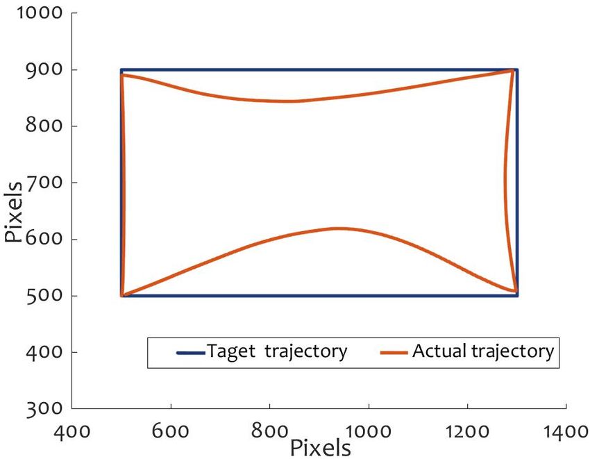
You can also read