MANUAL - INSTALLATION + SERVICE - Price Industries
←
→
Page content transcription
If your browser does not render page correctly, please read the page content below
MANUAL – INSTALLATION + SERVICE

   Price Intelligent Controller
   PIC Series

v400 – Issue Date: 01/14/20
© 2020 Price Industries Limited. All rights reserved.

PRICE INTELLIGENT CONTROLLER
  TABLE OF CONTENTS
Product Overview                                                                           BACnet Wiring............................................................. 36
  General.......................................................................... 1      Termination.................................................................. 36
  Input/Output Description................................................ 3               Electrical Noise............................................................. 36
  Price - Flow Response Chart.......................................... 4                  Network Wire Specifications......................................... 37
  Thermostat Overview..................................................... 5               BACnet Service Menu.................................................. 38
  Thermostat Installation................................................... 7             BACnet Networking and Setup.................................... 40
  Mounting Instructions..................................................... 8             Setting the Device Instance.......................................... 41
  Wiring............................................................................ 9   Maintenance
Balancing                                                                                  Troubleshooting............................................................ 43
  Balancing Instructions.................................................. 10              Hardware Specifications............................................... 46
Display Navigation
  Initial Startup................................................................ 12
  Info Menu..................................................................... 13
  Service Menu............................................................... 14
  Application Menu......................................................... 15
  Balancing Menu........................................................... 16
  VAV Menu.................................................................... 18
  VVT Menu.................................................................... 19
  Exhaust Box VAV Menu................................................ 20
  Dual Duct VAV Menu.................................................... 21
  VAV with Supply Exhaust Tracking Menu...................... 22
  VAV with Follower Menu............................................... 23
  Setpoint Menu.............................................................. 24
  Discharge Air Temperature Menu.................................. 26
  Input Menu................................................................... 27
  Output Menu - FAN...................................................... 29                SUPPORT
  Output Menu - Heat..................................................... 30
                                                                                         Having difficulty installing this product?
  Output Menu - Cool..................................................... 31             Price is here to help.
  Output Menu - Room Lights......................................... 32
                                                                                         Application Support
  BACnet Menu.............................................................. 33
  Stat Setup Menu.......................................................... 34
                                                                                         204.654.5613

  Display Options Menu.................................................. 35              controls@priceindustries.com
BACnet Networking                                                                        priceindustries.com/literature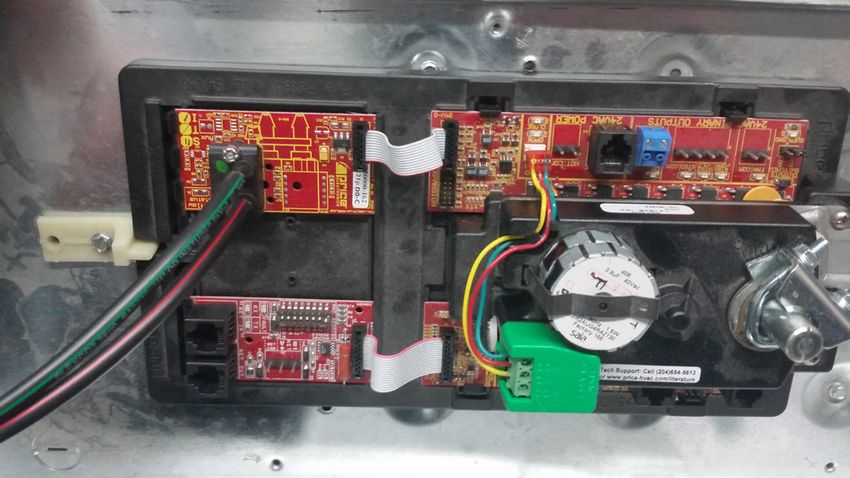
PRICE INTELLIGENT CONTROLLER
PRODUCT OVERVIEW
General
PIC - Price Intelligent Controller
maximum control and efficiency. An advanced and configurable
The Price Intelligent Controller (PIC) is a direct digital controller
proportional integral controller allows for exceptional user
for VAV terminals or fan coils that offers cutting edge zone
comfort and energy efficiency. Installation of the controller and
control. The PIC combines the accuracy of direct digital control
thermostat is simple and error proof with RJ-45 (network type)
with the flexibility of an individual room control system, providing
connections to the thermostat and BACnet network.
The PIC typically comes factory mounted to Price VAV boxes,
but may also be ordered stand-alone for retrofit jobs.
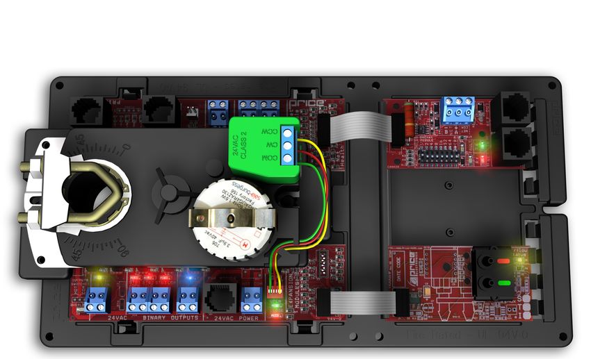
PIC - PRICE INTELLIGENT CONTROLLER
S.A.T. SENSOR CONTACT CLOSURE INPUT
T-STAT PORT FOR INPUT
THERMOSTAT
CONNECTION
4 ANALOG OUTPUTS
OPTIONAL BACNET
EXPANSION MODULE
SERVICE PORT FOR
PRICE LINKER
DAMPER ACTUATOR
SWITCHABLE
24 VAC HOT/COM
OUTPUT SELECTION
HOT OR COM
PLUGGABLE 24 VAC POWER OPTIONAL VAV
TERMINAL OR RJ-12 POWER CONNECTION EXPANSION MODULE
FAN OUTPUT
LED INDICATION FOR
TROUBLESHOOTING BINARY COOLING OUTPUT
3 BINARY STAGED HEATING OUTPUTS
priceindustries.com | PRICE INTELLIGENT CONTROLLER - Manual 1
PRICE INTELLIGENT CONTROLLER
                  Expansion Modules
PRODUCT OVERVIEW
                                    The Price Intelligent Controller is also expandable for BACnet networking capabilities, a
                                    Independent control. The expansion modules come equipped with a ribbon cable that
The PIC controller is an advanced and
                                               PIC-VAV
                                    from the PIC  to the selected module.
fully configurable VAV terminal controller
that can be used as either a pressure
dependant or a pressure independent •          (PIC-VAV) - VAV module (optional) provides airflow sensing for true VAV contro
zone control system.
When used as a pressure dependant
controller, the flow rate is dependant
on inlet static pressure and damper
position.
When used as a pressure independent
controller, flow rate is constant with
the use of the VAV Expansion Module
(PIC-VAV) and airflow sensor. The PIC •        (PIC-BAC) BACnet module (optional) provides a native BACnet MS/TP interfac
can be used as a stand alone unit,                PIC-BAC
or can be interfaced into a BAS with
MS/TP BACnet capability using the
BACnet module (PIC-BAC). The PIC
controller offers 5 thermostat options
that provide a range of control from
room temperature sensing, all the way
to wireless control. With a variety of
output configurations, the PIC controller
can control analog heating and cooling
valves, fan motors, and other types
of analog devices. As well as On/Off
heating and cooling stages, On/Off fan
operation, fan coils, etc. With the use
of the LCD Thermostat with Motion, the
PIC can be used as a motion sensor and
lighting controller with different levels of
sensitivity, as well as system balancing
tool.

Expansion Modules
                                                                          www.priceelectronics.ca/PIC
                                                                                Page 4 of 44
The Price Intelligent Controller is also
expandable for BACnet networking
capabilities, and for Pressure
Independent control. The expansion
modules come equipped with a ribbon
cable that is easy to plug in from the PIC
to the selected module.
•   PIC-VAV: VAV module (optional)
    provides airflow sensing for true VAV
    control.
•   PIC-BAC: BACnet module (optional)
    provides a native BACnet MS/TP
    interface for networking.

2    PRICE INTELLIGENT CONTROLLER - Manual | priceindustries.com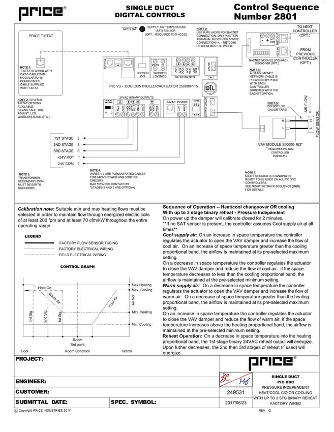
PRICE INTELLIGENT CONTROLLER
PRODUCT OVERVIEW
Input/Output Description
 24VAC Binary Outputs
 Fan Output                     Binary Output for On/Off control of a fan, three types:
                                Intermittent - Fan runs when there's a call for heating or cooling.
                                Day/Night - During the Day cycle the fan is on, during the Night cycle the fan is off.
                                Constant - Fan runs continuously
 Stage 1                        Binary (electric, or binary hot water)
                                Tristate (floating) close signal of hot water valve
 Stage 2                        Binary (electric, or binary hot water)
                                Tristate (floating) close signal of hot water valve
 Stage 3                        Binary (electric, or binary hot water)
                                24VAC PWM to SSR (10 second period)
 Cool/Aux                       Binary Output for one stage of cooling if required. Can be used as an auxiliary binary output if required.
 Analog Outputs
 ECM AO1                        Analog Output for any type of modulating fan (0-10VDC, 2-10VDC, 10-2VDC, etc.)
 AO2 Heat                       Analog Output for modulating heating valve (0-10VDC, 2-10VDC, 10-2VDC, etc.)
 AO3 Cool                       Analog Output for modulating cooling valve (0-10VDC, 2-10VDC, 10-2VDC, etc.)
 AO4 - Spare                    Spare analog output - normally indicates damper position (0-10VDC = 0-100%)
 Inputs
 Contact Closure                Configurable Binary Input can be used for night setback, damper force open/close etc.
 SAT Sensor                     Analog Input for temperature probe hookup for heat/cool changeover if required. 10k Type J
                                Thermistor

Switched HOT/COM Jumper: PIC offers a jumper selectable HOT/COM switch that allows the binary output to be switched
HOT or switched COMMON.
COM Terminals: All COM terminals on the PIC controller are internally connected, which allows for a common reference point
throughout the board.
Damper Actuator: Factory installed and wired, the PIC offers LED indication of the damper direction, (either OPEN or CLOSE).
Default drive time of the actuator is 90 seconds, but is configurable by using the LCD Thermostat.
NOTE: Drive time must match actuator being used; changing damper drive time does not make a 90 second actuator drive faster.
T-Stat RJ-45 Port: The PIC and thermostats comes equipped with an RJ-45 port to provide ease of plugging in a thermostat
cable from the PIC to any of the selected thermostats. The thermostat cable is supplied by Price.
Service Port: The PIC comes equipped with an RJ-12 port to provide ease of plugging in an RJ-12 cable to connect an
LCD setup tool for system balancing and setup. (LCD Setup tool only required for applications with dial, wireless or blank face
thermostats for regular operation)

                                                                     priceindustries.com | PRICE INTELLIGENT CONTROLLER - Manual         3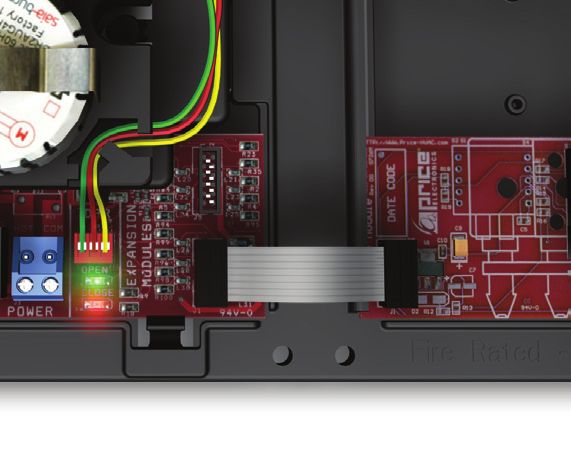
PRICE INTELLIGENT CONTROLLER
PRODUCT OVERVIEW
Price - Flow Response Chart
                                                                                                                     Neutral Supply
                 HCCO box                       Cooling Min     Cooling Flows      Heating Min     Heating Flows
                                                                                                                       Air Flow
     PI = Cooling         Duct Air = Cold                               x
     PI = Heating         Duct Air = Cold                                                x
     PI = Neutral         Duct Air = Cold             x

     PI = Cooling          Duct Air = Hot             x
     PI = Heating          Duct Air = Hot                                                                 x
     PI = Neutral          Duct Air = Hot             x

     PI = Cooling        Duct Air = Neutral                                                                                 x
     PI = Heating        Duct Air = Neutral                                              x
     PI = Neutral        Duct Air = Neutral                                                                                 x

NOTE 1: If no Temperature Probe is present, the PIC controller assumes cold duct air.
NOTE 2: PI = Proportional Integral = room load (either cooling/neutral/heating)
Above is a Flow Response chart for the PIC controller, showing the demand, Duct Air condition, and the controller's output.
E.g. PI = Cooling, Duct Air = Cold, Output = Cooling Flows. This indicates that the Room Demand is in Cooling, the Duct Air is
Cold, and the controller would modulate between the Cool Min and Cool Max values.

           TECH TIP
Use the above table to determine what airflows are being chased in certain modes.
Examples: If PIC is trying to heat the room (PI = heating) and cool air is being supplied (Duct air = Cold) it will chase its heating
min flow.

4    PRICE INTELLIGENT CONTROLLER - Manual | priceindustries.com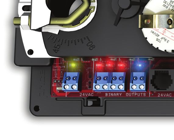
PRICE INTELLIGENT CONTROLLER
PRODUCT OVERVIEW
Thermostat Overview                         •   Temperature Setpoint limits are set
                                                through the T-Stat setup menus,             ROOM SENSOR THERMOSTAT
Room Sensor Thermostat                          free setup software using the Price
•   The Room Sensor Thermostat is               LINKER, or through a BACnet
    powered from the controller.                system.

•   Measures room temperature.              •   The LCD Thermostat can be used
                                                as a balancing tool for the controller
•   Setpoint can be adjusted from a             system by connecting the RJ-45
    hidden dial on the back of the T-Stat       cable to the back of the thermostat.
    using a small flat-head screw driver.
                                            LCD Thermostat with Motion Sensor
•   Setpoint limits can be adjusted
    through free setup software using       •   The LCD Thermostat with Motion
    the Price LINKER, or through a              Sensor is powered from the
    BACnet system.                              controller and has a variety of
                                                features as well.
                                                                                            DIAL THERMOSTAT
•   Eliminated problem of unauthorized
    tampering to the thermostat.            •   This model measures room
                                                temperature, features an LCD screen
•   Occupancy button can be used                with day Setpoint adjustment, and
    to override the system during               motion sensor with lighting control.
    unoccupied times. Default setting is
    4 hours.                                •   Temperature Setpoint limits are set
                                                through the T-Stat setup menus,
Dial Thermostat                                 free setup software using the Price
                                                LINKER, or through a BACnet
•   The Dial Thermostat is powered from         system.
    the controller.
                                            •   Balancing and additional setup
•   Measures room temperature and               functions are also available through
    features a dial adjustment and an                                                       LCD THERMOSTAT
                                                the menus.
    occupancy button.
                                            •   This thermostat can also be used as
•   Temperature Setpoint limits can be          a motion sensor for occupied and
    adjusted through free setup software        unoccupied times in a space. It also
    using the Price LINKER, or through a        has the capability to act as a lighting
    BACnet system.                              controller for occupied/unoccupied
                                                schedules.
•   Simply use the adjustable dial for
    temperature adjustment.                 NOTE: All thermostats are connected
•   Occupancy button can be used            with a CAT-5 cable (RJ-45) connection
    to override the system during           from the PIC to the back of the selected
    unoccupied times. Default setting is    thermostat. Each thermostat has an RJ-
    4 hours.                                12 Service Port on the bottom, providing
                                                                                            LCD THERMOSTAT W/ MOTION
                                            an interface for the LCD setup tool for
LCD Thermostat                                                                              SENSOR
                                            setup and balancing, and without having
•   The LCD Thermostat is powered           to access the plenum.
    from the controller and has a variety
    of features.

•   Measures room temperature and
    features an LCD screen with push
    button day Setpoint adjustment.

                                                                 priceindustries.com | PRICE INTELLIGENT CONTROLLER - Manual   5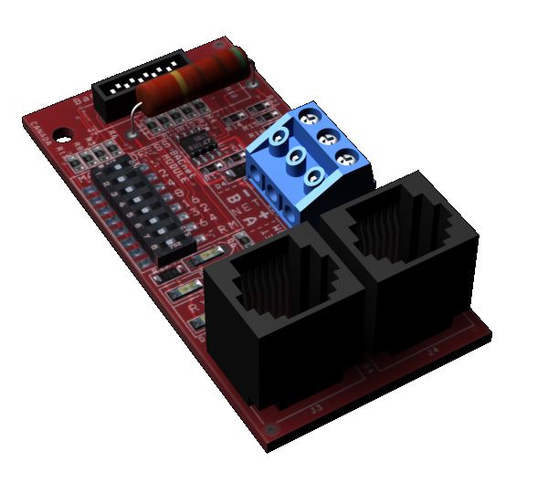
PRICE INTELLIGENT CONTROLLER
PRODUCT OVERVIEW
The Price Wireless Thermostat System provides both sensor          REMOTE T-STAT and BASE units talk between each other
inputs and a point of control for Price controllers.               wirelessly in the 2.4GHz range (FCC and IC certified). BASE unit
The System consists of 2 units:                                    connects to main controller using the supplied plenum-rated
                                                                   CAT-5 cable. No other connections are required.
WIRELESS REMOTE T-STAT - Transmitter - Room sensor
T-Stat with dial setpoint adjust, LED and push button.             NOTE: An LCD setup tool must still be used to setup and
                                                                   balance a PIC with the wireless thermostat option, the Wireless
WIRELESS BASE - Receiver - Unit with LCD and 3 push                LCD base cannot access the PIC's service menu.
buttons.

    WIRELESS THERMOSTAT

      Base (Receiver) Mounted in Plenum                                            Remote (Transmitter) User Thermostat
      •   LCD Screen for menu display                                              •   Dial Adjustment for Temperature
      •   Increase and decrease push buttons for                                   •   LED – 1 blink cooling mode, 2 – heating,
          day temperature setpoint adjustment                                          3 – neutral
      •   Service Port - Linker Connection                                         •   Occupancy Override Button
      •   Menu Button                                                              •   Service Port - Linker Connection

6    PRICE INTELLIGENT CONTROLLER - Manual | priceindustries.com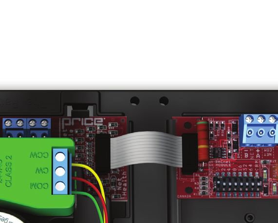
or directly to drywall using anchors supplied
                                                                                  2. Run the cable through the center hole in the p
                                                                                     secure the thermostat onto the wall plate ins
                                                                                     snapping the bottom half in.
PRICE INTELLIGENT CONTROLLER                                                      3. The thermostat will come equipped with a 0.0
PRODUCT OVERVIEW
Thermostat Installation                                                     SURFACE MOUNT DETAIL
General Description
The PIC thermostats are all physically the same size and
mounting instructions will be typical.                                            1.25" (32MM)
Location
1.   The Price Intelligent Controller (PIC) Thermostats must
     be mounted to a wall and wired to the controller via the
     supplied plenum rated 35ft CAT-5 cable. This cable plugs
     into the thermostat and the PIC controller with the ease of
     RJ-45 connections. NOTE: the cable run can be extended
     to 70 ft using a Price Cable coupler and additional 35ft
     cable.                                                                                                      WALL FASTENERS         TECH
                                                                                                                   BY OTHERS
                                                                                                                                        issue
2. Mount the required thermostat in a place that is
   convenient for the end user, but the following should be                                                                             Dam
   taken into consideration:

     • Do not mount a thermostat in direct sunlight i.e. across
       from a window where heat can alter the temperature
       reading.

     • Should not be installed on an outside wall.
                                                                            NETC35
     • Keep away from hot equipment like computers,
       monitors and heaters etc.                                             How to use the Dial Thermostat
     • Ensure nothing will restrict vertical air circulation to the
       thermostat. (Do Not Cover)                                                                          •    The Dial Thermostat is po
     • Ensure wall is NOT pressurized! Hot/Cold air from a
                                                                                                           •    Measures room temperat
       pressurized wall will direct blow onto the thermostat’s                                                  button.
       temperature sensor causing ‘bad’ readings.                                                          •    Temperature Setpoint lim
Installation
                                                                                                                the Price LINKER, or throu
1.   The back plate on each thermostat is removable and can
                                                                                                           •    Simply use the adjustable
     be mounted to a standard electrical box or directly to                                                •    Occupancy button can be
     drywall using anchors supplied by others.                                                                  times. Default setting is 4
2.   Run the CAT-5 cable through the center hole in the plate.
     Connect the cable to the thermostat, then secure the
     thermostat onto the wall plate inserting top portion of the
     thermostat first, then snapping the bottom half in.

3.   All thermostats will come equipped with a 0.050” Allen                                                                     www.price
     Key for the set screw at the bottom.
                                                                                                                                    Page

         TECH TIP
Careful thermostat installation will reduce field issues! Do not twist or kink the blue CAT-5 thermostat cable. Damaged cables are
difficult to troubleshoot!

A thermostat whose cable has been kinked will display the message 'Waiting for Link Check Wiring'

Thermostat cable product code: NETC35

                                                                      priceindustries.com | PRICE INTELLIGENT CONTROLLER - Manual   7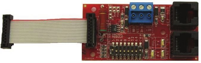
PRICE INTELLIGENT CONTROLLER
PRODUCT OVERVIEW
Support: Having difficulty installing or configuring this product? Price is here to help.
Controls Application Support: 204.654.5613 | controls@priceindustries.com | priceindustries.com/resources/type/literature

Mounting Instructions
Mount the PIC by sliding the actuator U-bolt over the damper
shaft. The back end of the PIC is secured by installing the
white plastic keeper (tied to the actuator motor with an elastic
band) with two sheet metal screws. This keeps the PIC from
moving when the actuator is turning, but still allows it to “float”
to avoid binding on the shaft if the controller were screwed
firmly in place.
Rotate the damper shaft all the way in one direction (either            PLASTIC KEEPER
clockwise or counter-clockwise) and then depress the gray
pivot clutch on the actuator, located directly below the green
terminal block, to unlock the actuator, and rotate it all the way
in the same direction the shaft was rotated in.
Tighten the nuts on the U-bolt clamp and secure the actuator
to the damper shaft.
Depress the clutch again and verify the actuator and shaft can
rotate through the full 90° range of motion.
NOTE: It does not matter if you choose clockwise or
counter-clockwise to rotate the shaft and actuator
before tightening the nuts. The PIC will calibrate on
power up. All that matters is that the damper shaft and
actuator have the full 90° range of motion.
                                                                          CLUTCH
Connect any of the controller's outputs as required.                     LOCATION
NOTE: When the output loads require a switched HOT or
COMMON 24VAC signal. Use the jumper near the FAN output
to select HOT or COMMON outputs.
Power the PIC using 24VAC, the secondary 24VAC common
of the transformer must be earth grounded, or power with
Price PPM power module by plugging the supplied cables into
the RJ-12 power jacks.

8    PRICE INTELLIGENT CONTROLLER - Manual | priceindustries.com
PRICE INTELLIGENT CONTROLLER
PRODUCT OVERVIEW
Wiring
Below is an example of a typical PIC sequence diagram - Single duct box with 3 stages of binary heat. Each PIC has a sequence
pre-programmed at the factory, however many adjustments can be made in the field with an LCD thermostat.
priceindustries.com | PRICE INTELLIGENT CONTROLLER - Manual 9PRICE INTELLIGENT CONTROLLER
DISPLAY NAVIGATION
Support: Having difficulty installing or configuring this product? Price is here to help.
Controls Application Support: 204.654.5613 | controls@priceindustries.com | priceindustries.com/resources/type/literature
Balancing Instructions
For more advanced setup details, please see 'Display Navigation' section.
Hold down the Menu button on the LCD Thermostat for
THEN
5 seconds until prompted for a passcode; use and
5 SECONDS to enter the passcode; DOWN, UP, UP, DOWN.
SERVICE MENU: The screen will now display “Service Menu: Application.”
APPLICATION
Scroll down to the Balancing sub-menu.
Press the Menu button to enter this menu.
SERVICE MENU:
THEN
BALANCING
DPR. OVERRIDE: Screen will now show “Damper Override Disabled.” Press
THEN Menu, and now “Disabled” will be flashing; this means you can
DISABLED
now scroll UP or DOWN with the arrow keys to select a target
to send the damper to.
DPR OVVERIDE:
For most applications, you will want to select “Go To Cool
THEN Max,” and once selected, the thermostat will read the actual
GOTO COOL MAX
CFM (position) and target CFM as the damper tries to lock on
to the cooling max airflow.
POS. TARGET
120CFM 250 CFM NOTE: If the target is zero, airflows must be entered in the
VAV sub-menu – refer to page 18 of this manual.
Another option to override the damper is the “Flow Override” function. This will cause the damper to target any specific airflow that
may not be a cooling or heating min/max flow.
When the screen is displaying “Flow Override,” press the
FLOW OVERRIDE
THEN Menu button and “No Override” will begin flashing. Press the
NO OVERRIDE
UP arrow key to select a CFM value for the damper to target.
FLOW OVERRIDE Press Menu to select the value and press the DOWN arrow
THEN
NO OVERRIDE key to view the damper position vs target screen. The position
should increase steadily until the target is reached.
POS TARGET
120 CFM 200 CFM NOTE: “Flow Override” must be set back down to “No
Override” once complete.
Once the thermostat says that the position and target are the same, an airflow reading can now be taken from the air outlets.
Compare your instrument’s reading to what the thermostat is reading for an airflow. Some adjustment may be required.
Adjustments are made in the 'Airflow Factor' menu, or, depending on the version of the controller, the 'Airflow Tweak' menu.
10 PRICE INTELLIGENT CONTROLLER - Manual | priceindustries.comPRICE INTELLIGENT CONTROLLER
DISPLAY NAVIGATION
For Controllers with Airflow Factor Menu
If any adjustment is required, press the 'DOWN' arrow key, the
thermostat will now read 'AIRFLOW FACTOR' and will display
AIRFLOWFACTOR its current CFM reading. Press the menu button and the CFM
THEN reading will change to display the current K factor, and the
250 CFM
value will be flashing, indicating it is ready to be changed using
the arrow keys.
AIRFLOWFACTOR Adjust the K factor by the percentage high or low that the
OR balancing hood is reading versus the thermostat. For example,
890
if the thermostat reads 250 CFM, but the balancer’s hood
reads 300 CFM, then divide 250 by 300 to get 0.833, this
means the controller is reading 83.3% of what the balancer's
hood is reading, so the K factor must be adjusted up.
Supposing the box is an 8” inlet size, the K factor would be
890, so you would divide 890 by .833, and the new corrected
K factor would be 1068.
K adjusted = K original / (CFM stat / CFM hood)
For Controllers with Airflow Tweak Menu
To make adjustments on controllers with airflow tweak instead
of airflow factor, scroll to the airflow tweak menu. The screen
AIRFLOW TWEAK will display the current CFM. Press the menu button and the
THEN CFM reading will change to a flashing '0%'.
250 CFM
Adjust the % by the percentage high or low that the balancing
AIRFLOW TWEAK
OR hood is reading versus the thermostat. For example, if the
0%
thermostat reads 250 CFM, but the balancer’s hood reads 300
CFM, follow the formula below to calculate the % higher or
lower to offset the tweak.
Tweak = (1 / (CFM stat / CFM hood) - 1)*100
Now, the thermostat’s displayed CFM should much more closely match the hood’s CFM reading.
Tech Support - CALL 204 654-5613 option 4
controls@priceindustries.com
priceindustries.com | PRICE INTELLIGENT CONTROLLER - Manual 11PRICE INTELLIGENT CONTROLLER
DISPLAY NAVIGATION
Initial Startup
(LCD & Motion Thermostat only)
When the LCD thermostat is powered from the PIC, it will display the following information:
PRICE ELECTRONICS Start-up screen
LCD THERMOSTAT
Standard/Motion Model
STANDARD MODEL
LCD THERMOSTAT
Displays firmware version of thermostat
VERSION X.XX
LOADING:
Loading parameters
INITIALIZING
PIC
Controller type and controller firmware version
VERSION X.XX
Displays sequence programmed into stat
SEQUENCE XXXX
NOTE: a sequence number of 0 means the stat has NOT been calibrated
MAC ADDRESS XXX Displays current MAC Address
DEVICE INST. XXXXXXX Displays current Device Instance
ROOM TEMP. 75.0°F (For example)
Changing the Setpoint – LCD & Motion Thermostat only
Day Setpoint Adjustment
Increase and decrease push buttons for Day Setpoint adjustment
DAY SETPOINT
75.0°F
DAY SETPOINT
SAVING...
12 PRICE INTELLIGENT CONTROLLER - Manual | priceindustries.comPRICE INTELLIGENT CONTROLLER
DISPLAY NAVIGATION
Info Menu
(LCD & Motion Thermostat only)
The Info menu shows information about the controller status regarding room load, damper position and BACnet Address info.
No values can be changed from this menu and it is not locked or protected in any way.
Press ‘Enter Menu’ button to enter the User Menu, scroll through using the up and down buttons.
APPLICATION AIR
Single duct or fan powered terminal unit
TERMINAL
OCCUPANCY ON
The Occupancy can be determined by airflow, contact closure, motion or by a user pressing a button
VVT MODE
Neutral mode mean PI controller is satisfied
NEUTRAL MODE LOAD
Cooling -1 to -100%
0%
Heating +1 to +100%
SUPPLY AIR TEMP If no supply probe is present, LCD will display no probe
85.0°F If supply probe present, LCD will display temperature
DAMPER POSITION This indicates the current position of the damper is percent (%)
50% Range is 0-100% (100% = full open or maximum air)
ECM OUTPUT
Current output on the AO1
1.5 DVC
AIRFLOW
Only displayed if system is pressure independent (PIC-VAV module attached)
300 CFM
FLOW TARGET Shows the current flow target in CFM (VAV) or % (VVT)
300 CFM NOTE: if damper position (above) is at 100% and CFM target is not being met, the box is STARVING for AIR
CO2 READING The current CO2 reading in PPM (Parts Per Million)
HUMIDITY READING The current humidity reading in RH% (relative humidity)
Shows the BACnet MAC address. Range 1-99
MAC ADDRESS
MAC Address can be set via dip in software switch, or in software with the LCD thermostat / setup tool
1
If no BACnet module attached, LCD will display MAC address None
(Instance must be "globally" unique on your site)
DEVICE INSTANCE
Displays controller's BACnet Device Instance (if BACnet is attached)
101
Device Instance can range from 0-4, 194, 303
PRESS MENU
NOTE: Info menu will automatically time out after 20 seconds
TO EXIT
priceindustries.com | PRICE INTELLIGENT CONTROLLER - Manual 13PRICE INTELLIGENT CONTROLLER
DISPLAY NAVIGATION
Service Menu
(LCD Setup only)
Hold down 'Enter/Menu' button for 5 seconds, display will show 'Passcode:'. Use Up and Down keys to enter the password in
this sequence: Down, Up, Up, Down.
SERVICE MENU:
Change the Application the unit is operating as
APPLICATION
SERVICE MENU:
Allows you to force the damper open/close/min/max
BALANCING
Allows you to set flows or set limits
For VAV (Air Terminal application only)- page 17
For VVT (Air Terminal application only) - page 18
SERVICE MENU:
For Exhaust Box VAV (Exhaust Box application only) - page 19
VAV/VVT
For Dual Duct (Dual Duct application only) - page 20
For Discharge Air Temp (Fan Coil applications only) - page 21
For VAV with Flow Follower (Flow Follower application only - page 22 & 23
SERVICE MENU: Setup of Setpoint limits (day minimum/maximum).
SETPOINT °F/°C selection
SERVICE MENU: Shows supply air temperature reading.
INPUT Shows if VAV and BACnet modules are attached.
SERVICE MENU: Allows setup of FAN, HEAT, COOL, outputs.
OUTPUT Allows setup of room light output (motion stat only).
Allows setup of BACnet addresses
SERVICE MENU:
MAC address, Device Instance Baud Rate
BACNET
Included only if BACnet module is attached
SERVICE MENU: Allows setup of LCD back lighting, sounds, motion sensor.
STAT SETUP Adjustment of HVAC and room lighting time-outs.
PRESS MENU
NOTE: Service menu will automatically time out after 20 seconds
TO EXIT
14 PRICE INTELLIGENT CONTROLLER - Manual | priceindustries.comPRICE INTELLIGENT CONTROLLER
DISPLAY NAVIGATION
Application Menu
Scroll through menu with 'Up' and 'Down' keys. Press Enter/Menu' button to apply your changes.
*---Saving---* will display as your changes are applied.
APPLICATION
CONTROL APPLICATION AIR TERMINAL For typical single duct and fan powered terminals units
FANCOIL 4 PIPE Fan coil 4-pipe with hot and cold water
FANCOIL 2 PIPE Fan coil 2-pipe with hot and cold changeover
DUAL DUCT Dual duct terminal units with hot and cold inlets
EXHAUST BOX Exhaust terminal unit typically with constant flow
SUPPLY & EXHAUST
Volumetric offset supply and exhaust applications
TRACKING
MIXING BOX DAT Mixes airstreams to maintain a specific discharge air temp
CO2 TRACKING Tracks airflow proportionally to the current CO2 in the occupied space
PRESS MENU
TO EXIT
TECH TIP
Depending on which application is selected, determines whether some
menus with appear. Each menu item that is affected specifically states when
it is visible.
priceindustries.com | PRICE INTELLIGENT CONTROLLER - Manual 15PRICE INTELLIGENT CONTROLLER
DISPLAY NAVIGATION
Balancing Menu
Scroll through menu with 'Up' and 'Down' keys. Press Enter/Menu' button to apply your changes.
*---Saving---* will display as your changes are applied.
(Not visible if the application is Dual Duct)
BALANCING
Go to Cool Min - Chases cool min flow
Go to Cool Max - Chases cool max flow
Go to Heat Min - Chases heat min flow
DAMPER OVERRIDE Go to Heat max - Chases heat max flow
DISABLED Go to Neutral Flow - Force damper full open
Go to Full open - Force damper full close
Display shows current target and position
Allow 1-5 minutes for damper to meet target within 5%
PIC will remain in this mode until user exits the menu
(Only visible if the application is Dual Duct)
Disabled - Default
Cold Setpoint, Hot Close - Cold deck chases setpoint, Hot deck closes
Cold Minimum, Hot Close - Cold deck goes to minimum, Hot deck closes
Cold Close, Hot Setpoint - Cold deck closes, Hot deck chases setpoint
DUAL DAMPER
Cold Close, Hot Minimum - Cold deck closes, Hot deck goes to minimum
OVERRIDE
50/50 Mixed - Cold deck and hot deck go to 50%
Cold Open, Hot Close - Cold deck opens, Hot deck closes
Cold Close, Hot Open - Cold deck closes, Hot deck opens
Both Full Open - Cold and hot deck both open
Both Full Close - Cold and hot deck both close
(Only visible if the application is Dual Duct)
COLD FLOW TWEAK
Adjust Cold flow reading by +/- 100%
(Only visible if the application is Dual Duct)
HOT FLOW OVERRIDE
Adjust Hot flow reading by +/- 100%
(Only visible if the application is Flow Follower)
MAIN BOX TWEAK
Adjust main box flow reading by +/- 100%
(Only visible if the application is Flow Follower)
AIRFLOW TWEAK/
Adjust follower flow reading by +/- 100% Airflow Tweak
FOLLOWER TWEAK
Allows user to adjust airflow reading to match flow hood
Continue to next page...
16 PRICE INTELLIGENT CONTROLLER - Manual | priceindustries.comPRICE INTELLIGENT CONTROLLER
DISPLAY NAVIGATION
Balancing Menu
Scroll through menu with 'Up' and 'Down' keys. Press Enter/Menu' button to apply your changes.
*---Saving---* will display as your changes are applied.
Continued from previous page...
This menu allows you to put in a CFM value that you want to target and check out the VAV
damper, and if the air handler is pushing enough air to the box. Eg. Set the Flow Override value
to 200 CFM and hit Enter, then hit the Down arrow button to view the current damper position
FLOW OVERRIDE
and the target of the damper. If the position gets to 200 CFM, then there is enough air pushing
NO OVERRIDE
to the VAV box.
NOTE: Once complete with the Flow Override check, put this value back to zero or
No Flow Override.
This value is the actual CFM flowing across the crossflow sensor and through the box. From
here, push the menu button once, and this will display the current K factor value for that box. Eg.
AIRFLOW FACTOR
8” box = 890 K factor. You can adjust this factor if required.
See example in Balancing section, page 11 of this manual
PRESS MENU
TO EXIT
priceindustries.com | PRICE INTELLIGENT CONTROLLER - Manual 17PRICE INTELLIGENT CONTROLLER
DISPLAY NAVIGATION
VAV Menu
(Pressure independent mode)
Scroll through menu with Up and Down keys. Press 'Enter/Menu' button to apply your changes. *---Saving---* will display as your
changes are applied.
DUCT SIZE Allows selection of inlet size (4", 5", 6", 7", 8", 9", 10", 12", 14",16")
VAV
8 INCHES NOTE: Changing duct size will load the default min/max airflow for that size
FLOW UNITS
Choose between liters per second or cubic feet per minute
CFM
COOL MIN FLOW
Sets the cool min flow. Must be lower than (or same as) cool max flow
132 CFM
COOL MAX FLOW
Sets the cool max flow. Must be higher than (or same as) cool max flow
800 CFM
HEAT MIN FLOW
Sets the heat min flow. Must be lower than (or same as) heat max flow
132 CFM
HEAT MAX FLOW
Sets the heat max flow. Must be lower than (or same as) heat min flow
800 CFM
NEUTRAL FLOW
Sets the neutral flow. Independent with no limits
132 CFM
When the PIC is unoccupied, the damper will rest at this position.
UNOCCUPIED DAMPER
Default - 40% (Range 0-100%) 100% = full open
POSITION - 40%
CFM default - 132 cfm.
DAMPER RUNTIME Change the total runtime of the damper (this changes the time that the PIC applies
95 SEC the open/close signal to the actuator, but cannot make the actuator run fatser)
DAMPER DIRECTION
Changes which direction open and close are set to
NORMAL
DAMPER Normal - damper will calibrate on startup
CALIBRATION No Cal Mode - damper will not calibrate on startup
DAY FLOW TRIP PIC will go into occupied mode when CFM reading is equal or greater than this value
66 CFM Default: 1/2 the box minimum flow
PIC will go into unoccupied mode when CFM reading is equal or greater or less than this value
NIGHT FLOW TRIP
AND damper is starved at 100%
33 CFM
Default: 1/4 the box minimum flow
Enabled - occupied and unoccupied modes triggered by airflow.
AIRFLOW NSB
(If enabled day flow trip & night flow trip trigger occupied/unoccupied mode)
DISABLED
Disabled - occupied and unoccupied modes not triggered by airflow.
Normal - uses the Flow Chart to determine the damper target.
FLOW
Duct Temp Use PI - this feature ignores the Flow Chart and uses the PI to determine the damper target.
RESPONSE
Eg. PI is in cooling mode, damper will target Cooling Min and Max flows.
PRESS MENU
TO EXIT
18 PRICE INTELLIGENT CONTROLLER - Manual | priceindustries.comPRICE INTELLIGENT CONTROLLER
DISPLAY NAVIGATION
VVT Menu
(Pressure dependent mode)
Scroll through menu with Up and Down keys. Press 'Enter/Menu' button to apply your changes. *---Saving---* will display as your
changes are applied.
COOL MIN FLOW Cool min flow in %
VVT
0% Range: 0-100% Default: 10%
COOL MAX FLOW Cool max flow in %
100% Range: 0-100% Default: 100%
HEAT MIN FLOW Heat min flow in %
0% Range: 0-100% Default: 10%
HEAT MAX FLOW Heat max flow in %
100% Range: 0-100% Default: 100%
NEUTRAL FLOW Sets the neutral flow
0% Range: 0-100% Default: 10%
When PIC is unoccupied, the damper will rest at this position.
UNOCCUPIED DAMPER
Default - 40% (Range 0-100%) 100% = full open
POSITION - 40%
CFM default - 132 cfm.
DAMPER RUNTIME
Change the total runtime of the damper.
95 SEC
DAMPER DIRECTION
Changes which direction open and close are set to
NORMAL
Normal - uses the Flow Chart to determine the damper target.
FLOW Duct Temp Use PI - this feature ignores the Flow Chart and
RESPONSE uses the PI to determine the damper target.
Eg. PI is in cooling mode, damper will target Cooling Min and Max flows.
PRESS MENU
TO EXIT
priceindustries.com | PRICE INTELLIGENT CONTROLLER - Manual 19PRICE INTELLIGENT CONTROLLER
DISPLAY NAVIGATION
Exhaust Box VAV Menu
(Application specific options)
Scroll through menu with Up and Down keys. Press 'Enter/Menu' button to apply your changes. *---Saving---* will display as your
changes are applied.
EXHAUST CONFIG Constant volume - PIC will try to maintain a constant volume
EXHAUST BOX VAV
CONST VOLUME Track Analog Signal - PIC will maintain a volume proportional to an analog signal
DUCT SIZE Allows selection of inlet size (4", 5", 6", 7", 8", 9", 10", 12", 14",16", 24” x 16",
8 INCHES and low profiles of 9", 10", 12", 14", 16")
FLOW UNITS
Choose between liters per second or cubic feet per minute
CFM
EXHAUST MIN FLOW
Minimum airflow to be maintained, corresponds to input Signal minimum
132 CFM
EXHAUST MAX FLOW
Maximum airflow to be maintained, corresponds to input Signal maximum
800 CFM
INPUT SIGNAL MIN
Minimum analog signal, corresponds to input exhaust minimum flow
00 VDC
INPUT SIGNAL MAX
Maximum analog signal, corresponds to input exhaust maximum flow
100 VDC
CONSTANT VOLUME
1000 cfm default
SETPOINT
When PIC is unoccupied, the damper will rest at this position.
UNOCCUPIED DAMPER
Default - 40% (Range 0-100%) 100% = full open
POSITION - 40%
CFM default - 132 cfm.
Enabled - occupied and unoccupied modes triggered by airflow.
AIRFLOW NSB
(If enabled day flow trip & night flow trip trigger occupied/unoccupied mode)
ENABLED
Disabled - occupied and unoccupied modes not triggered by airflow.
DAMPER RUNTIME
Change the total runtime of the damper
95 SEC
DAMPER DIRECTION
Changes which direction open and close are set to
NORMAL
DAY FLOW TRIP PIC will go into occupied mode when CFM reading is equal or greater than this value
66 CFM Default: 1/2 the box minimum flow
PIC will go into unoccupied mode when CFM reading is equal or greater or less than this value
NIGHT FLOW TRIP
AND damper is starved at 100%
33 CFM
Default: 1/4 the box minimum flow
Normal: Allows the damper to calibrate on start up
DAMPER CALIBRATION
No Cal: Disables damper calibration on startup
PRESS MENU
TO EXIT
20 PRICE INTELLIGENT CONTROLLER - Manual | priceindustries.comPRICE INTELLIGENT CONTROLLER
DISPLAY NAVIGATION
Dual Duct VAV Menu
(Application specific options)
Scroll through menu with Up and Down keys. Press 'Enter/Menu' button to apply your changes. *---Saving---* will display as your
changes are applied.
DUAL DUCT TYPE Constant Volume - Maintains a constant volume as set in constant Volume setpoint
DUAL DUCT VAV
CONSTANT VOLUME Variable Volume - Varies volume between Hot/Cold Deck min/max flows
Allows selection of inlet size (4", 5", 6", 7", 8", 9", 10", 12", 14",16", 24” x 16",
COLD DECK SIZE
and low profiles of 9", 10", 12", 14", 16")
8 INCHES
NOTE: Changing duct size will load the default min/max airflow for that size
Allows selection of inlet size (4", 5", 6", 7", 8", 9", 10", 12", 14",16", 24” x 16",
HOT DECK SIZE
and low profiles of 9", 10", 12", 14", 16")
8 INCHES
NOTE: Changing duct size will load the default min/max airflow for that size
FLOW UNITS
Choose between liters per second (L/s) or cubic feet per minute (cfm)
CFM
CONSTANT VOLUME
Sets the constant airflow to maintain
SETPOINT 800 CFM
COLD DECK MIN FLOW
Minimum cold deck flow to maintain
132 CFM
COLD DECK MAX FLOW
Maximum cold deck flow to maintain
800 CFM
HOT DECK MIN FLOW
Minimum hot deck flow to maintain
132 CFM
HOT DECK MAX FLOW
Maximum hot deck flow to maintain
800 CFM
When PIC is unoccupied, the damper will rest at this position.
UNOCCUPIED DAMPER
Default - 40% (Range 0-100%) 100% = full open
POSITION 40%
CFM default - 132 cfm.
DAMPER RUNTIME
Change the total runtime of the damper
95 SEC
DAY FLOW TRIP (Active if Airflow NSB is enabled) PIC will go into occupied mode when CFM reading
66 CFM is greater than or equal to this value. Default: 1/2 the box minimum flow
NIGHT FLOW TRIP (Active if Airflow NSB is enabled) PIC will go into occupied mode when CFM reading is less than
33 CFM or equal to this value AND damper is starved at 100%. Default: 1/4 the box minimum flow
Enabled - occupied and unoccupied modes triggered by airflow
AIRFLOW NIGHT
If enabled dat flow trip & night flow trip trigger occupied/unoccupied mode
SETBACK
Disabled - occupied and unoccupied modes not triggered by airflow
DAMPER DIRECTION
Changes which direction open and close are set to
NORMAL
Normal: Allows the damper to calibrate on start up and after every 500 movements
DAMPER CALIBRATION
No Cal: Disables damper calibration on startup and after every 500 movements
PRESS MENU
TO EXIT
priceindustries.com | PRICE INTELLIGENT CONTROLLER - Manual 21PRICE INTELLIGENT CONTROLLER
DISPLAY NAVIGATION
VAV with Supply Exhaust Tracking Menu
(Application specific options)
Scroll through menu with Up and Down keys. Press 'Enter/Menu' button to apply your changes. *---Saving---* will display as your
changes are applied.
Allows selection of inlet size (4", 5", 6", 7", 8", 9", 10", 12", 14",16", 24” x 16",
VAV WITH FOLLOW DUCT SIZE
and low profiles of 9", 10", 12", 14", 16")
8 INCHES
NOTE: Changing duct size will load the default min/max airflow for that size
Allows selection of inlet size (4", 5", 6", 7", 8", 9", 10", 12", 14",16", 24” x 16",
EX. DUCT SIZE
and low profiles of 9", 10", 12", 14", 16")
8 INCHES
NOTE: Changing duct size will load the default min/max airflow for that size
FLOW UNITS
Choose between liters per second or cubic feet per minute
CFM
COOL MIN FLOW
Minimum cooling flow
132 CFM
COOL MAX FLOW
Maximum cooling flow
800 CFM
HEAT MIN FLOW
Heat minimum flow
132 CFM
HEAT MAX FLOW
Heat maximum flow
800 CFM
NEUTRAL FLOW
Flow when controller is satisfied
132 CFM
EXHAUST OFFSET
Applies an offset to the exhaust flow
0 CFM
When PIC is unoccupied, the damper will rest at this position.
UNOCCUPIED DAMPER
Default - 40% (Range 0-100%) 100% = full open
POSITION - 40%
CFM default - 132 cfm.
Continue to next page...
22 PRICE INTELLIGENT CONTROLLER - Manual | priceindustries.comPRICE INTELLIGENT CONTROLLER
DISPLAY NAVIGATION
VAV with Follower Menu
(Application specific options)
Scroll through menu with Up and Down keys. Press 'Enter/Menu' button to apply your changes. *---Saving---* will display as your
changes are applied.
Continued from previous page...
UNOCCUPIED DAMPER When PIC is unoccupied damper will "rest" at this position
POSITION 40% Range: 0-100% Default: 40% (Reminder: 100% = full open)
DAMPER RUNTIME
Change the total runtime of the damper
95 SEC
DAMPER DIRECTION
Changes which direction open and close are set to
NORMAL
DAMPER CAL Damper reads after a set number of movements (Normal is Default)
NORMAL (No Cal Mode) The damper is remains direct flow but assumes the damper position
DAY FLOW TRIP PIC will go into occupied mode when CFM reading is equal or greater than this value
66 CFM Default: 1/2 the box minimum flow
PIC will go into unoccupied mode when CFM reading is equal or less than this value AND
NIGHT FLOW TRIP
damper is starved at 100%
33 CFM
Default: 1/4 the box minimum flow
Enabled - occupied and unoccupied modes triggered by airflow (if enabled
AIRFLOW NSB
day flow trip & night flow trip trigger occupied/unoccupied mode)
ENABLED
Disabled - occupied and unoccupied modes not triggered by airflow
Normal - uses the Flow Chart to determine the damper target.
FLOW Duct Temp Use PI - this feature ignores the Flow Chart and uses the PI to determine the damper
REPONSE target.
Eg. PI is in cooling mode, damper will target Cooling Min and Max flows.
PRESS MENU
TO EXIT
priceindustries.com | PRICE INTELLIGENT CONTROLLER - Manual 23PRICE INTELLIGENT CONTROLLER
DISPLAY NAVIGATION
Setpoint Menu
(Setpoint Limits and Temperature Units)
Scroll through menu with Up and Down keys. Press 'Enter/Menu' button to apply your changes. *---Saving---* will display as your
changes are applied.
SET LOW LIMIT This is the lowest setpoint allowed.
SETPOINT
65.0F Range: 10.0°F - 100.0°F Default: 65.0°F
SET HIGH LIMIT This is the highest setpoint allowed.
80.0F Range: 10.0°F - 100.0°F Default: 80.0°F
TEMPERATURE UNITS Fahrenheit or Celsius
FAHRENHEIT Default: °F
NIGHT HEAT SET PIC will maintain this heating setpoint when unoccupied.
62.0F Range: 10.0°F - 100.0°F Default: 62.0°F
NIGHT COOL SET PIC will maintain this cooling setpoint when unoccupied.
83.0F Range: 10.0°F - 100.0°F Default: 83.0°F
PROPORTIONAL BAND Default 2°F, 1°C
2.0F Proportional Band is the range of control or the throttling range of the device.
DAY DIFFERENTIAL 1°F, 0.5°C
1.0F Day Differential is the deadband on either side of the setpoint.
PI Damper - sets the proportional/integral response of the damper.
Normal PI - Damper responds in normal PI mode during heating, cooling or neutral mode.
PI DAMPER Low Range PI- Damper will respond in the low range of the PI from 0-50% during heating, cooling
NORMAL PI or neutral mode.
Hi Range PI - Damper will respond in the high range of the PI from 50-100% during heating,
cooling or neutral mode.
PI Analog Heat - sets the proportional/integral response of the Analog Heating output - A02.
PI ANALOG HEAT Normal PI - Heating output responds normally during a call for heat from 0-100%.
NORMAL PI Low Range PI- Heating output responds during the low range of the PI from 0-50%.
Hi Range PI - Heating output responds during the high range of the PI from 50-100%.
PI Analog Cool - sets the proportional/integral response of the Analog Cooling output - A03
PI ANALOG COOL Normal PI - Cooling output responds normally during a call for heat from 0-100%.
NORMAL PI Low Range PI- Cooling output responds during the low range of the PI from 0-50%.
Hi Range PI - Cooling output responds during the high range of the PI from 50-100%.
PI ECM Heat - sets the proportional/integral response of the Analog ECM Fan output- A01, during
a call for heating.
Normal PI - Analog Fan output responds normally from 0-10VDC during a call for heat.
PI ECM HEAT
Low Range PI - Analog Fan output operates from 0-10VDC during the Low Range of the Analog
NORMAL PI
Heat output.
Hi Range PI - Analog Fan output operates from 0-10VDC during the High Range of the Analog
Heat output.
Continue to next page...
24 PRICE INTELLIGENT CONTROLLER - Manual | priceindustries.comPRICE INTELLIGENT CONTROLLER
DISPLAY NAVIGATION
Setpoint Menu Continued
(Setpoint Limits and Temperature Units)
Scroll through menu with Up and Down keys. Press 'Enter/Menu' button to apply your changes. *---Saving---* will display as your
changes are applied.
Continued from previous page...
PI ECM Cool - sets the proportional/integral response of the Analog ECM Fan output- A01, during
a call for cooling.
Normal PI - Analog Fan output responds normally from 0-10VDC during a call for cooling.
PI ECM COOL
Low Range PI - Analog Fan output operates from 0-10VDC during the Low Range of the Analog
NORMAL PI
Cool output.
Hi Range PI - Analog Fan output operates from 0-10VDC during the High Range of the Analog
Cool output.
PRESS MENU
TO EXIT
priceindustries.com | PRICE INTELLIGENT CONTROLLER - Manual 25PRICE INTELLIGENT CONTROLLER
DISPLAY NAVIGATION
Discharge Air Temperature Menu
(Application specific options)
Scroll through menu with Up and Down keys. Press 'Enter/Menu' button to apply your changes. *---Saving---* will display as your
changes are applied.
DISCHARGE AIR Peeking - Currently checking to determine Hot/Cold water
ASSUME H2O TYPE
TEMPERATURE Hot
PEEKING
Cold
Dynamic: When water temperature is below room temp it is considered cooling.
When water temperature is above room temp it is considered heating. This mode is
H2O TEMPERATURE recommended because PIC will always use the supply air if it can help satisfy the room load
DETECT DYNAMIC Conventional, Force Cool, Force Heat: Conventional uses Hot and Cold switch points. Force
Cool, Force Heat always assumes cold or hot. These modes are not recommended
Hot Switch - Only visible when H20 - Temperature Detect = Conventional
HOT SWITCH PIC will consider the supply air warm if at the hot switch temp or above
81.0°F Default: 0.0°F - uses dynamic neutral mode (neutral mode disabled)
COLD SWITCH PIC will consider the supply air cold if at the cold switch temp or below
73.0°F Default : 0.0°F - uses dynamic neutral mode (neutral mode disabled)
DISCHARGE AIR TEMP.
Current temperature of the probe mounted to water pipe
NO PROBE
DAT COOL SETPOINT
Cooling setpoint
55.0°F
DAT HEAT SETPOINT
Heating Setpoint
90.0°F
DAT WHILE PI IS IN
What the temperature will be maintain when the system is satisfied
DEADBAND 0.0°F
DAT SERVICE TIME
DAT will calculate and move the valve every 60 seconds (default)
60 SEC
DAT STEP DIVISION
Distance a single step travels (leave at default 10)
10
DAT STEP MAXIMUM
Maximum change a call for heating or cooling can make during a step
10%
DAT DIFFERENTIAL
The range that the controller is satisfied and will not make adjustments
2.0°F
PEEK MIN TIME
Minimum amount of time controller will open the valve to check if system is heating or cooling
5 MIN
PEEK FAN SPEED
The fan speed during the peek time
21%
PEEK OCCURANCE The moment the valve is shut, this timer will start counting down. When it expires,
360 MIN the controller will open the valve to check on the water temperature.
PRESS MENU
TO EXIT
26 PRICE INTELLIGENT CONTROLLER - Manual | priceindustries.comPRICE INTELLIGENT CONTROLLER
DISPLAY NAVIGATION
Input Menu
(Supply air temperature and neutral mode)
Scroll through menu with Up and Down keys. Press 'Enter/Menu' button to apply your changes. *---Saving---* will display as your
changes are applied.
Shows current SAT reading if probe connected
INPUT SUPPLY AIR
Range: -59.0°F - 300.0°F
TEMPERATURE
No probe, means no sensor is connected
When supply air temperature (SAT) is below room temperature it is considered cooling.
When supply air temperature (SAT) is above room temperature it is considered heating.
This mode is recommended because PIC will always use the supply air if it can help satisfy the
NEUTRAL MODE room load.
DYNAMIC Neutral Mode = Conventional, Force Cool, Force Heat
Conventional uses Hot and Cold switch points.
Force cool, Force Heat always assumes cold or hot.
Not Recommended
Hot Switch - Only active/visible when Neutral Mode = Conventional
HOT SWITCH
PIC will consider the supply air warm if at hot switch temp or above.
81.0F
Default: 0.0 DegF - uses dynamic neutral mode (Neutral mode disabled)
Cold Switch - Only active/visible when Neutral Mode = Conventional
COLD SWITCH
PIC will consider the supply air cold if at cold switch temp or below.
73.0F
Default: 0.0 DegF - uses dynamic neutral mode (Neutral mode disabled)
Attached - VAV Module is being used and sensing airflow.
VAV MODULE
Not Attached - VAV Module is not attached or disabled in software.
Pressure Type - not visible if application is Fancoil 2 pipe of Fancoil 4 pipe
PRESSURE TYPE VAV VAV Auto: VAV module is being used and sensing airflow.
AUTO VVT Manual: VAV module Disabled in software (Override)
VVT Auto: no VAV module - VVT Mode
ROOM TEMPERATURE
Apply an offset to the room temperature.
OFFSET - 0.0F
SAT OFFSET
Apply an offset to the SAT temperature.
0.0F
All Output Halt - disables all output
Disable Binary Cool
Disable Binary Heat
Disable Binary Fan
Disable AO4
Idle Analog Cool - default 0 VDC
CONTACT CLOSURE
Idle Analog Heat - default 0 VDC
CONFIGURATION
Idle Analog ECM - default 1.5 VDC
Damper full close
Damper full open - Default
Occupied when closed - Forces occupied
Unoccupied on closed - Forces unoccupied
Not used - Disabled
Continue to next page...
priceindustries.com | PRICE INTELLIGENT CONTROLLER - Manual 27PRICE INTELLIGENT CONTROLLER
DISPLAY NAVIGATION
Input Menu Continued
(Supply air temperature and neutral mode)
Scroll through menu with Up and Down keys. Press 'Enter/Menu' button to apply your changes. *---Saving---* will display as your
changes are applied.
Continued from previous page...
CO2 SENSOR
Indicates that the CO2 sensor is connected
DETECTED
CO2 TWEAK Percentage that the CO2 reading can be tweaked if required.
0% Default is 0%
CO2 OFFSET Value to offset CO2 reading if required.
0 PPM Default is 0 PPM
CO2 PURGEMODE This feature is only active when the C02 and humidity thermostat is
ENABLED connected to the PIC controller. Purge mode is enabled here
PURGE AIRFLOW
Set purge Airflow to desired cfm - 800 cfm is default
800 CFM
MAX CO2 LEVEL 1000
PIC controller will initiate purge ode above this value. Default CO2 setting is 1000 ppm
PPM
NOMINAL CO2 PIC controller will purge until Nominal CO2 level is met. Default
800 PPM is 800 ppm. Nominal CO2 is your target CO2
HUMIDITY SENSOR
Indicates that the Humidity (RH) sensor is connected
DETECTED
HUMIDITY TWEAK Percentage that the RH reading can be tweaked if required.
0% Default is 0%
HUMIDITY OFFSET
Value to offset RH reading if required. Default is 0%RH
0%RH
PRESS MENU
TO EXIT
28 PRICE INTELLIGENT CONTROLLER - Manual | priceindustries.comPRICE INTELLIGENT CONTROLLER
DISPLAY NAVIGATION
Output Menu - FAN
(Setup of fan outputs)
Scroll through menu with Up and Down keys. Press 'Enter/Menu' button to apply your changes. *---Saving---* will display as your
changes are applied.
OUTPUT
Allows configuration of ECM COOL MIN PI cooling min (-1 to -100%) output voltage
OUTPUT FAN
fan outputs 2.1 VDC Default 2.1 VDC
ECM COOL MAX PI cooling max (-100%) output voltage
8.0 VDC Default 8.0 VDC
ECM HEAT MIN PI heating max (+100%) output voltage
2.1 VDC Default 2.1 VDC
ECM HEAT MAX PI heating min (+1 to +100%) output voltage
8.0 VDC Default 8.0 VDC
ECM DEADBAND PI in neutral/deadband (0%)
1.5 VDC Output voltage defaults to 1.5 VDC
ECM UNOCCUPIED Unoccupied voltage for ECM motor
1.5 VDC Default = 1.5 VDC (Fan Off)
This controls the binary FAN output
BINARY FAN TYPE
Constant = fan output always on
Fan is on when PI is heating or cooling (+1 to +100%
FAN TYPE HEAT & COOL
or -1 to -100%) (Day & night mode)
During the day, fan is always on
FAN TYPE DAY & NIGHT
During the night, the fan is only on when PI is heating or
HEAT / COOL
cooling (+1 to +100% or -1 to -100%)
FAN TYPE CONTINUOUS Fan is always on
During the day, fan is always on
FAN TYPE DAY & NIGHT
During the night, the fan is only on when
HEAT
PI is heating (+1 to +100%)
OUTPUT HEAT
FAN TYPE
Fan on when PI heating (+1 to +100%) (Day & night mode)
HEATING
ANALOG OUTPUT
FAN TYPE
Fan output disabled
PRESS MENU NO FAN
TO EXIT
priceindustries.com | PRICE INTELLIGENT CONTROLLER - Manual 29PRICE INTELLIGENT CONTROLLER
DISPLAY NAVIGATION
Output Menu - Heat
(Setup of heat outputs)
Scroll through menu with Up and Down keys. Press 'Enter/Menu' button to apply your changes. *---Saving---* will display as your
changes are applied.
OUTPUT
OUTPUT FAN
Reheat Type: Binary, Hot Water, Binary/PWM, Hot Water/PWM
OUTPUT HEAT
Binary uses Stage 1, 2, 3 - Default
Hot water uses Stage 1 & 2 for Open/Close
Binary/PWM and Hot Water/PWM -- Stage 3 is PWM
REHEAT TYPE - Bin-HotAirDis - Binary reheat outputs are disabled when hot air is sensed at the inlet
BINARY - H.W.HotAirDis - Hot Water reheat output is disabled when hot air is sensed at the inlet
- BinPWM-HtArDs - Binary/PWM reheat output is disabled when hot air is sensed at the inlet
- HW/PWM-HtArDs - Hot Water/PWM reheat output is disabled when hot air is
sensed at the inlet
- Reheat Disable - Reheat outputs are disabled
DRIVE TIME Hot water runtime in seconds
90 SECONDS Not shown if BINARY heat is used
HEAT STAGE 1 Heat Stage 1 Trip Point: Stage 1 engages at 33% heating
33% Not shown if hot water heat is used
HEAT STAGE 2 Heat Stage 2 Trip Point: Stage 2 engages at 66% heating
66% Not shown if hot water heat is used
HEAT STAGE 3
Heat Stage 3 Trip Point: Stage 3 engages at 100% heating
100%
REHEAT FAIL SAFE Off - Outputs send 24VAC on call for heat
OFF On - Outputs send 24VAC when no call for heat (fail open valve in cold climates - ie: Winnipeg)
ANALOG HEAT MIN
Outputs this voltage on heat analog pin when there is a minimum call for heating
0.0 VDC
ANALOG HEAT MAX
Outputs this voltage on heat analog pin when there is a maximum call for heating
10.0 VDC
ANALOG HEAT IDLE
Outputs this voltage on heat analog pin when there is no call for heating
0.0 VDC
ANALOG OUTPUT
Disabled: (Default) this means the controller will enable the heat as normal.
AF INTERLOCK Enabled: when enabled, the heating outputs will not energize until at least 87.5% of the
OUTPUT ROOM LIGHTS
Minimum Heating Flow is sensed at the cross-flow sensor
PRESS MENU PRESS MENU
TO EXIT TO EXIT
30 PRICE INTELLIGENT CONTROLLER - Manual | priceindustries.comYou can also read