Electronic flow switch with display For liquid media Model FSD-4
←
→
Page content transcription
If your browser does not render page correctly, please read the page content below
Flow
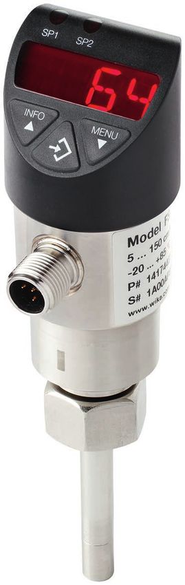
Electronic flow switch with display
For liquid media
Model FSD-4
WIKA data sheet FL 80.02
Applications
■ Control of cooling lubricant systems
■ Monitoring of coolant circuits
■ Control of filter units
■ Dry run protection in pumps
Special features
■ Wear-free flow monitoring of liquid media using the
calorimetric principle
■ Flexibly configurable switching and analogue outputs for
flow and temperature
■ Easily parameterisable via 3-button operation or optionally
via IO-Link 1.1
■ Exact adaptation to the conditions on-site
Electronic flow switch, model FSD-4
Description
The model FSD-4 electronic flow switch offers full flexibility in Flexibly configurable switching outputs
monitoring and controlling flow based on the velocities of liquid Depending on the configuration, the model FSD-4 has up to
media. The switch points of the model FSD-4 can be freely two switch points plus analogue output, which can be freely
configured very easily via the 3-button operation directly on programmed. Since the switch determines its flow data using
the instrument or optionally via IO-Link. The model FSD-4 can a calorimetric measurement principle, the second switching
output both absolute values in various units and relative flow output can also be enabled for a temperature value, while the
values and display them on the digital indicator. first outputs a switching signal using the flow value. The flow
switch can thus additionally be used for simple temperature-
Exact matching to the conditions on-site controlled processes.
The flow is determined by many factors such as the pipe
diameter, the system set-up or the medium. Therefore, Easy access via IO-Link version 1.1
depending on the application, the actual flow value may differ The parameters are set either via 3-button operation on the
from the calibrated value. Thanks to the teach function, the instrument or, optionally, via IO-Link. When changing the
model FSD-4 can be set to the zero point and the maximum instrument, the settings for the respective measuring location
flow at the respective measuring location and thus optimally can be transferred directly to the new flow switch. This
adjusted to the measuring conditions. The compression fitting eliminates the need for any repeat parameterisation at the
on the flow switch offers additional flexibility. Depending on measuring location and reduces the necessary integration
the pipe diameter, the immersion depth and alignment can effort. With IO-Link, additional functions such as an operating
be individually adjusted. hours counter or max value memory can be called up and
used for condition monitoring.
WIKA data sheet FL 80.02 ∙ 04/2021 Page 1 of 11
Data sheets showing similar products:
Electronic pressure switch with display; model PSD-4; see data sheet PE 81.86
Electronic temperature switch with display; model TSD-30; see data sheet TE 67.03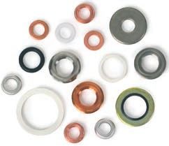
Specifications

The model FSD-4 features a flow outlet as standard. A temperature output is available as an option.

 Accuracy specifications
 Accuracy under calibration conditions         The accuracy of the flow switch depends on various parameters such as flow profile, flow
                                               conditions, viscosity and/or thermal conductivity of the medium, possible contamination and/
                                               or deposits on the sensor. Therefore, the reference measured values given only constitute an
                                               accuracy under calibration conditions.
                                               The model FSD-4 offers extensive adjustment possibilities to adapt the instrument to the on-
                                               site conditions in the best possible way.
                                               As a flow switch it is used for reliable monitoring, for example, of dry running. The flow value
                                               output should only be used as a trend indicator in order to monitor process changes.
    Flow                                       0.05 ... ≤ 1 m/s             ≤ ±5 % of end value of measuring range
                                               > 1 ... ≤ 1.75 m/s           ≤ ±10 % of end value of measuring range
                                               > 1.75 ... 3 m/s             ≤ ±20 % of end value of measuring range
    Temperature                                ≤ ±2 K
 Non-repeatability per IEC 62828-1
    Flow                                       ±2 % of end value of measuring range
    Temperature                                ≤ 0.5 K (for flow ≥ 0.2 m/s)
 Temperature error, flow at -20 ... +85 °C     0.13 % of end value of measuring range per K (typical)
 [-4 ... +185 °F]
 Reference conditions                          Per IEC 62828-1
 Calibration conditions
    Medium                                     Water
    Nominal position                           Process connection downwards
                                               Inner diameter of pipe 26 mm
                                               Upstream/Downstream pipe 1 m/0.5 m
                                               Marking towards the upstream flow side ±5° twist

 Measuring range
 Measuring range
    Flow                           0 ... 3 m/s [0 ... 9.84 ft/s]
                                   The in-factory adjustment is carried out with the medium water.
                                   It is recommended to carry out the adjustment, relative to the minimum/maximum flow of the system, via
                                   the menu.
    Temperature                    -20 ... +85 °C [-4 ... +185 °F]
 Turndown ratio (flow or           The analogue output signal is freely scalable within the range of 5:1
 temperature)                      When setting turndown, there is a proportional increase in the measuring deviation and temperature error.
 Digital display
    Indication range               14 segments
    Unit                           Flow               %, m/s, l/min, m³/h, ft/s, ft³/min, gal(US)/min, gal(I)/min
                                                      Factory setting: m/s
                                   Temperature        °C, °F
                                                      Factory setting: °C
                                   The units are freely configurable.
    Colour                         Red (LED)
    Character size                 9 mm [0.35 in]
    Digits                         4-digit
    Display                        The display can be rotated electronically through 180°.

WIKA data sheet FL 80.02 ∙ 04/2021                                                                                                   Page 2 of 11
Process connection
Standard Thread Insertion length L Sealing
ISO 225-1 M18 x 1.5 52 mm [2.05 in] FPM/FKM
DIN EN ISO 1179-2 G¼A 28 mm [1.1 in] ■ NBR (standard)
(formerly DIN 3852-E) ■ FPM/FKM (option)
G½A 30 mm [1.18 in]
■ Without (option)
G½A 49 mm [1.93 in]
G½A 79 mm [3.11 in]
G½A 119 mm [4.69 in]
ANSI/ASME B1.20.1 ¼ NPT 22 mm [0.87 in] -
½ NPT 38 mm [1.5 in] -
- 1) Without 140 mm [5.51 in] -
1) For version with compression fitting
Output signal
When ordering the FSD-4, only one of the three following output signal variants has to be selected. The signal type, as
well as the assignment of the second switching output and the analogue output, can be individually programmed during
commissioning.
IO-Link is optionally available for all output variants.
Output signal Switching output 1 Switching output 2 Analogue output IO-Link option
Output variant 1 x x - x
Output variant 2 x - x x
Output variant 3 x x x x
Further details on: Output signal
Signal type
Switching output 1 ■ Flow, PNP
■ Flow, NPN
Factory setting: Flow, PNP
Switching output 2 ■ Flow, PNP
■ Flow, NPN
■ Temperature, PNP
■ Temperature, NPN
Factory setting: Flow, PNP
Analogue output ■ Flow, 4 ... 20 mA
■ Flow, 0 ... 10 V
■ Temperature, 4 ... 20 mA
■ Temperature, 0 ... 10 V
Factory setting: Flow, 4 ... 20 mA
IO-Link IO-Link is optionally available for all output signal configurations.
Switching function ■ Hysteresis
■ Window
Factory setting: Hysteresis
Contact function ■ Normally closed
■ Normally open
Factory setting: Normally open
WIKA data sheet FL 80.02 ∙ 04/2021 Page 3 of 11Further details on: Output signal
Setting range of the switch points
Flow 0.05 ... 3 m/s [0.16 ... 9.84 ft/s]
Factory setting: 3 m/s
Temperature -18.2 ... +85 °C [-0.8 ... +185 °F]
Factory setting: 85 °C
Switch hysteresis
Flow Adjustable, min. 1.7 % of end value of measuring range
Factory setting: 0.3 m/s
Temperature Min. 1.8 K
Factory setting: 1.8 K
Load in Ω
Analogue signal 4 ... 20 mA ≤ 500 Ω
Analogue signal DC 0 ... 10 V > max. output voltage/1 mA
Signal clamping ■ Imin = 3.8 mA
■ Imax = 20.5 mA
■ Umin = 0 V
■ Umax = 10.3 V
Switching current 1) Max. 250 mA per switching output
Switching voltage Supply voltage - 1 V
Communication
Communication protocol IO-Link 1.1, if IO-Link option has been selected
Voltage supply
Supply voltage DC 15 ... 35 V
Current supply Max. 650 mA including switching current
Overvoltage protection DC 40 V
Dynamic properties per IEC 62828-1
Settling time Flow ■ 6 s (0 ... 100 %, 100 ... 0 %)
Temperature ■ 4 s (t90)
■ 2 s (t63)
Warm-up time 10 s
1) For max. switching currents, see derating curves on page 6.
Electrical connection
Connection type ■ Circular connector M12 x 1 (4-pin)
■ Circular connector M12 x 1 (5-pin) 1)
Pin assignment → See below
Ingress protection (IP code) IP65 and IP67
per IEC 60529 2)
Short-circuit resistance S+ / SP1 / SP2 vs. U-
Reverse polarity protection U+ vs. U-
Insulation voltage DC 500 V
1) Only for version with two switching outputs and additional analogue output signal.
2) The stated IP codes (per IEC 60529) only apply when plugged in using mating connectors that have the appropriate IP code.
WIKA data sheet FL 80.02 ∙ 04/2021 Page 4 of 11Pin assignment
Circular connector M12 x 1 (4-pin) Circular connector M12 x 1 (5-pin)
U+ 1 U+ 1
U- 3 U- 3
S+ / SP2 1) 2 S+ 5
SP1 / C 4 SP1 / C 4
SP2 2
1) Depending on the configuration of the output signals
Legend:
U+ Positive power supply terminal
U- Negative power supply terminal
SP1 Switching output 1
SP2 Switching output 2
S+ Analogue output
C Communication with IO-Link
Material
Material (wetted)
Process connection, probe Stainless steel 316Ti
Sealing → See “Process connection”
Material (in contact with the environment)
Case Stainless steel 304
Keyboard TPE-E
Display window PC
Display head PC+ABS blend
Operating conditions
Medium temperature range 1) -20 ... +85 °C [-4 ... +185 °F]
Ambient temperature range 1) -20 ... +70 °C [-4 ... +158 °F]
Storage temperature range -20 ... +80 °C [-4 ... +176 °F]
Derating curves → See below
Max. operating pressure ■ 40 bar [580 psi]
■ 30 bar [435 psi] with process connection M18 x 1.5
■ 20 bar [290 psi] with optional compression fitting (→ see “Accessories”)
Vibration resistance per IEC 60068-2-6 ■ 6 g, under resonance
■ 3 g, 10 ... 500 Hz (with compression fitting)
Shock resistance per IEC 60068-2-27 50 g, mechanical
Mounting position → See operating instructions
Ingress protection per IEC 60529 → See “Electrical connection”
Service life 100 million switching cycles
1) For permissible medium and ambient temperature, see derating curves on page 6.
WIKA data sheet FL 80.02 ∙ 04/2021 Page 5 of 11Derating curves
Max. ambient temperature, if ambient temperature ≥ medium Max. ambient temperature, if medium temperature
temperature = 85 °C [185 °F]
71,0 64,0
70,0 63,0
69,0
Ambient temperature/°C
68,0 62,0
Ambient temperature/°C
67,0
61,0
66,0
2 switches 2 switches
65,0 60,0
64,0
59,0
63,0
58,0
62,0 1 switches
61,0 1 switches 57,0
60,0
59,0 56,0
58,0 55,0
0 50 100 150 200 250 0 50 100 150 200 250
Switching current per channel/mA Switching current per channel/mA
Packaging and instrument labelling
Packaging Individual packaging
Instrument labelling ■ WIKA product label, glued
■ Customer-specific product label on request
Approvals
Approvals included in the scope of delivery
Logo Description Country
EU declaration of conformity European Union
EMC directive
EN 61326 emission (group 1, class B) and immunity (industrial application)
RoHS directive
UL USA and Canada
Safety (e.g. electr. safety, overpressure, ...)
Manufacturer's information
Logo Description
- China RoHS directive
→ Approvals and certificates, see website
Safety-related characteristic values
Safety-related characteristic values
MTTF > 100 years
WIKA data sheet FL 80.02 ∙ 04/2021 Page 6 of 11Dimensions in mm [in]
Weight: Approx. 0.3 kg [10.58 oz]
Process connections
DIN EN ISO 1179-2 ANSI/ASME B1.20.1 ISO 225-1
(formerly DIN 3852-E)
G F1 L1 G F1 L1 G F1 L1
G¼A 16 [0.63] 43 [1.69] ¼ NPT 16 [0.63] 42 [1.65] M18 x 1.5 46.2 [1.819] 52 [2.47]
G½A 16 [0.63] 43 [1.69] ½ NPT 30 [1.18] 62 [2.44]
35 [1.38] 62 [2.44]
65 [2.65] 92 [3.62]
105 [4.13] 132 [5.2]
WIKA data sheet FL 80.02 ∙ 04/2021 Page 7 of 11G F1 - 140 [5.51] Legend F1 Probe length L1 Insertion length WIKA data sheet FL 80.02 ∙ 04/2021 Page 8 of 11
Spare parts
Sealings           Description                                                                                    Order number
                   Profile sealing G ¼ A DIN EN ISO 1179-2 (formerly DIN 3852-E)       NBR                        1537857
                                                                                       FPM/FKM                    1576534
                   Profile sealing G ½ A DIN EN ISO 1179-2 (formerly DIN 3852-E)       NBR                        1039067
                                                                                       FPM/FKM                    1039075

Accessories
Circular connector M12 x 1 with moulded cable
Model          Description                Material     IP code      Temperature              Cable       Cable              Order
                                                                    range                    diameter    length             number
               Straight version, cut to   PUR          IP67         -20 ... +80 °C           4.5 mm      2 m [6.6 ft]       14086880
               length, 4-pin, UL listed                             [-4 ... +176 °F]         [0.18 in]
                                                                                                         5 m [16.4 ft]      14086883
                                                                                                         10 m [32.8 ft]     14086884
               Straight version, cut to                                                      5.5 mm      2 m [6.6 ft]       14086886
               length, 5-pin, UL listed                                                      [0.22 in]
                                                                                                         5 m [16.4 ft]      14086887
                                                                                                         10 m [32.8 ft]     14086888
               Angled version, cut to                                                        4.5 mm      2 m [6.6 ft]       14086889
               length, 4-pin, UL listed                                                      [0.18 in]
                                                                                                         5 m [16.4 ft]      14086891
                                                                                                         10 m [32.8 ft]     14086892
               Angled version, cut to                                                        5.5 mm      2 m [6.6 ft]       14086893
               length, 5-pin, UL listed                                                      [0.22 in]
                                                                                                         5 m [16.4 ft]      14086894
                                                                                                         10 m [32.8 ft]     14086896

WIKA data sheet FL 80.02 ∙ 04/2021                                                                                        Page 9 of 11
FSD-4 with adapter FSD-4 with compression fitting
Legend:
A Maximum probe immersion depth
B Distance between sealing face and probe tip
Adapters and compression fittings
Model Description Recommended B A Order number
for pipe ∅
From M18 x 1.5 to G ¼ 22 ... 50 mm 28 mm 16 mm 14242761
[0.86 ... 0.97 in] [1.10 in] [0.63 in]
From M18 x 1.5 to G ½, long 25 ... 60 mm 31 mm 17 mm 14242759
[0.98 ... 2.36 in] [1.22 in] [0.67 in]
From M18 x 1.5 to G ½, short 32 ... 100 mm 36 mm 22 mm 14242760
[1.26 ... 3.93 in] [1.41 in] [0.86 in]
Compression fitting, G 1/2 140 ... 400 mm 70 ... 110 mm 56 ... 96 mm 3199551
[5.51 ... 15.75 in] [2.76 ... 4.33 in] [2.2 ... 3.78 in]
WIKA data sheet FL 80.02 ∙ 04/2021 Page 10 of 11Adapters and compression fittings
Model Description Recommended B A Order number
for pipe ∅
Compression fitting, G 1/4 140 ... 400 mm 70 ... 110 mm 58 ... 98 mm 11193396
[5.51 ... 15.75 in] [2.76 ... 4.33 in] [2.28 ... 3.86 in]
Compression fitting, 1/2 NPT 140 ... 400 mm - 56 ... 96 mm 11397625
[5.51 ... 15.75 in] [2.20 ... 3.78 in]
Compression fitting, 1/4 NPT 140 ... 400 mm - 58 ... 98 mm 14268712
[5.51 ... 15.75 in] [2.28 ... 3.86 in]
Ordering information
Model / Output variant / Probe length / Process connection / Sealing / Accessories
© 03/2021 WIKA Alexander Wiegand SE & Co. KG, all rights reserved.
The specifications given in this document represent the state of engineering at the time of publishing.
We reserve the right to make modifications to the specifications and materials.
WIKA data sheet FL 80.02 ∙ 04/2021 Page 11 of 11
04/2021 EN
WIKA Alexander Wiegand SE & Co. KG
Alexander-Wiegand-Straße 30
63911 Klingenberg/Germany
Tel. +49 9372 132-0
Fax +49 9372 132-406
info@wika.de
www.wika.deYou can also read