Differential pressure gauge with microswitches With integrated working pressure indication (DELTA-comb) Model DPGS40 - WIKA Polska
←
→
Page content transcription
If your browser does not render page correctly, please read the page content below
Pressure
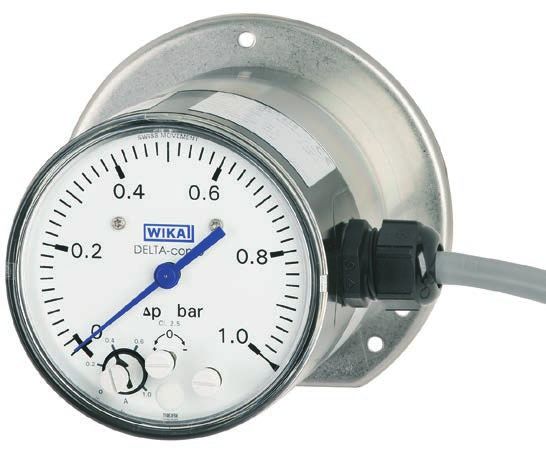
Differential pressure gauge with microswitches
With integrated working pressure indication (DELTA-comb)
Model DPGS40
WIKA data sheet PV 27.20
for further approvals
see page 6
DELTA-comb
Applications
Monitoring and control of filters, compressors and pumps for:
■ Boilers and pressure vessels
■ Drinking and cooling-water treatment plants
■ Pressure-boosting and pumping stations
■ Heating technology
■ Fire-extinguishing systems
Special features
■ With one or two adjustable microswitches
■ Shatterproof window and robust aluminium or stainless
steel measuring chamber for increased requirements
■ Optionally with approvals for hazardous areas
■ High ingress protection, IP65, for outdoor use and Fig. left: With aluminium measuring chamber
processes with high condensation Fig. right: With stainless steel measuring chamber
■ Low measuring range from 0 ... 250 mbar
Description
The differential pressure gauges of the DELTA-line product The switch point is accessible from the front and can be set
family are primarily used for the monitoring and control of low in the range of 10 ... 100 % of the end value of the measuring
differential pressures where there are high requirements in range by means of an assistant scale.
terms of one-sided overload and static pressure.
Typical markets for these products are the process heating The two easily readable, mechanical on-site displays need
technology, the heating, ventilation and air-conditioning no power supply and enable the simultaneous reading of
industries, the water/wastewater industry, and machine build- the working and the differential pressure. Furthermore, this
ing and plant construction. For these, the main function of the saves on an additional measuring and sealing point, reducing
measuring instruments is the monitoring and control of filters, additional expense for piping and mounting.
compressors and pumps.
The measuring chamber, depending on the requirement and
Wherever circuits need to be switched safely dependent on a application, can be made from aluminium or stainless steel.
defined differential pressure, the DELTA-switch finds its use. Through the increased stability, the stainless steel measuring
As the pressure passes above or below a defined set point, chamber is also suitable for gaseous media.
the switching operation is triggered.
WIKA data sheet PV 27.20 ∙ 05/2021 Page 1 of 10
Data sheets showing similar products:
DELTA-comb, differential pressure gauge with component testing; model DPGS40TA; see data sheet PV 27.22
DELTA-plus, differential pressure gauge; model DPG40; see data sheet PM 07.20
DELTA-trans, differential pressure gauge with output signal; model DPGT40; see data sheet PV 17.19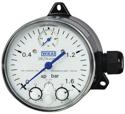
Functionality
The display case (1) is connected directly with the measuring
chamber (2) and the process connections integrated in it.
Pressures p1 and p2 act on the media chambers ⊕ and ⊖,
which are separated by an elastic diaphragm (3).
The differential pressure (∆p = p1 - p2) leads to an axial
deflection of the diaphragm against the measuring range
springs (4).
The deflection, which is proportional to the differential
pressure, is transmitted to the movement (10) in the indicator
14077593.01
case and to the leaf springs of the microswitches (7) via a
pressure-tight and low friction rocker arm (6).
Overload safety is provided by metal bolsters (5) resting
⊖ ⊕
against the elastic diaphragm.
With versions without Ex approval, the adjustment of the
switch point is made by the adjustment screws accessible
from the front (8). The assistant scales (9) simplify the setting
of the switch point.
For versions with Ex approval, the switch point setting is
made at the factory and cannot be carried out subsequently.
Overview of versions
Measuring chamber material Working pressure indication Ex approval
Aluminium Stainless steel Without Ø 22 mm
x x Option
x x Option
x x Option
→ For information on approvals, see page 6
Specifications
Basic information
Nominal size
Differential pressure display Ø 100 mm
Working pressure indication ■ Without
■ Ø 22 mm
Window
Non-Ex version Plastic, with plug screw for switch point setting
Ex version Plastic (switch point setting can only be carried out at the factory)
Case version Display case, aluminium, EN AC-AI Si9Cu3(Fe); black painted
→ Measuring chamber, see table “Measuring element”
WIKA data sheet PV 27.20 ∙ 05/2021 Page 2 of 10
Measuring element
Type of measuring element
   Differential pressure display                    Measuring chamber with diaphragm and media chambers ⊕ and ⊖
   Working pressure indication                      ■ Without
                                                    ■ Bourdon tube

Material
   Measuring chamber                                ■ Aluminium, EN AC–Al Si9Cu3(Fe), black painted
                                                    ■ Stainless steel 1.4571

   Diaphragm, sealings                              ■ FPM/FKM
                                                    ■ NBR

   Bourdon tube (working pressure indication)       Copper alloy

Accuracy specifications
Accuracy class
   Differential pressure display                    ■ 2.5
                                                    ■ 1.6 (only selectable for scale ranges from 0 ... 1 bar to 0 ... 10 bar)

   Working pressure indication                      4
Repeatability                                       ≤ 1.6 % of measuring span
Temperature error                                   On deviation from the reference conditions at the measuring system:
                                                    Max. ±0.8 %/10 K of end value of measuring range
Reference conditions
   Ambient temperature                              +20 °C [+68 °F]

Differential pressure measuring ranges
Measuring range                                                  Measuring range
mbar                                 psi                         kPa                                  MPa
   0 ... 250                           0 ... 15                       -12.5 ... +12.5                     0 ... 0.025
   0 ... 400                           0 ... 25                       0 ... 25                            0 ... 0.04
   0 ... 600                           0 ... 40                       0 ... 40                            0 ... 0.06
   0 ... 1,000                         0 ... 60                       0 ... 60                            0 ... 0.1
bar                                  kg/cm2                           0 ... 100                           0 ... 0.16
   0 ... 0.25                          0 ... 0.25                     0 ... 160                           0 ... 0.25
   0 ... 0.4                           0 ... 0.4                      0 ... 250                           0 ... 0.4
   0 ... 0.6                           0 ... 0.6                      0 ... 400                           0 ... 0.6
   0 ... 1                             0 ... 1                        0 ... 600                           0 ... 1
   0 ... 1.6                           0 ... 1.6                      0 ... 1,000
   0 ... 2.5                           0 ... 2.5
   0 ... 4                             0 ... 4
   0 ... 6                             0 ... 6
   0 ... 10                            0 ... 10

Scale ranges for working pressure
Scale range
bar
   0 ... 10
   0 ... 16
   0 ... 25

WIKA data sheet PV 27.20 ∙ 05/2021                                                                                          Page 3 of 10
Further details on: Measuring ranges
Type of pressure Differential pressure
Special measuring ranges Other measuring ranges on request
Unit ■ bar
■ psi
■ mbar
■ kg/cm²
■ MPa
■ kPa
Process connections
Standard ■ EN 837
■ DIN EN ISO 8434-1
Size
EN 837 ■ 2 x G ¼, female thread, centre distance 26 mm
■ 2 x G ¼ B, male thread, centre distance 26 mm
DIN EN ISO 8434-1 ■ 2 x bite-type fitting for pipe ∅ 6 mm
■ 2 x bite-type fitting for pipe ∅ 8 mm
■ 2 x bite-type fitting for pipe ∅ 10 mm
Materials (wetted)
Measuring chamber ■ Aluminium, Al Si9Cu3(Fe), black painted
■ Stainless steel 1.4571
Process connection ■ Identical to measuring chamber (only 2 x G ¼ female thread)
■ Copper alloy
■ Stainless steel
■ Steel (only bite-type fittings)
Diaphragm, sealings ■ FPM/FKM
■ NBR
Output signal
Connection method Microswitch
Number of switches ■ Single contact, contact model 850.3
■ Double contact, contact model 850.3.3
Switching function Change-over contact
Switch point setting From the outside at assistant scale by means of adjustment screw(s)
Non-Ex version ■ From the outside at assistant scale by means of adjustment screw(s)
Ex version ■ Factory set (subsequent switch point setting cannot be carried out)
Setting range From 10 % to 100 % of measuring range
Switch hysteresis ■ Max. 2.5 % of end value of measuring range
■ Max. 5 % of end value of measuring range
Electrical connections
Connection type ■ Cable gland M20 x 1.5 with 1 m cable, flying leads
■ Cable socket
■ Angular connector
Pin assignment → See drawings from page 8
WIKA data sheet PV 27.20 ∙ 05/2021 Page 4 of 10Operating conditions
Medium temperature -10 ... +90 °C [14 ... 194 °F]
Ambient temperature
Non-Ex version -10 ... +70 °C [14 ... 150 °F]
Ex version -10 ... +60 °C [14 ... 140 °F]
Storage temperature -20 ... +60 °C [-4 ... +140 °F]
Pressure limitation
Steady End value of measuring range
Fluctuating 0.9 x end value of measuring range
Overload safety Max. 25 bar
On one, both and alternatingly on the ⊕ and ⊖ sides
Ingress protection per IEC/EN 60529 IP65
WIKA data sheet PV 27.20 ∙ 05/2021 Page 5 of 10Approvals
Approvals included in the scope of delivery
Logo Description Country
EU declaration of conformity European Union
Pressure equipment directive
Low voltage directive
RoHS directive
- CRN Canada
Safety (e.g. electr. safety, overpressure, ...)
Optional approvals
Logo Description Country
EU declaration of conformity European Union
ATEX directive
Hazardous areas
Gas II 2G Ex ia IIC T4/T5/T6 Gb
Dust II 2D Ex ia IIIB T135°C Db
IECEx International
Hazardous areas
Gas Ex ia IIC T4/T5/T6 Gb
Dust Ex ia IIIB T135°C Db
EAC Eurasian Economic
Hazardous areas Community
UkrSEPRO Ukraine
Metrology, measurement technology
Ex Ukraine Ukraine
Hazardous areas
Uzstandard Uzbekistan
Metrology, measurement technology
GOST Russia
Metrology, measurement technology
KazInMetr Kazakhstan
Metrology, measurement technology
- MTSCHS Kazakhstan
Permission for commissioning
BelGIM Belarus
Metrology, measurement technology
Certificates (option)
Certificates
Certificates ■ 2.2 test report per EN 10204 (e.g. state-of-the-art manufacturing, indication accuracy)
■ 3.1 inspection certificate per EN 10204 (e.g. indication accuracy)
Recommended recalibration interval 1 year (dependent on conditions of use)
→ Approvals and certificates, see website
WIKA data sheet PV 27.20 ∙ 05/2021 Page 6 of 10Safety-relevant characteristic values (explosion-protected version)
Safety-related characteristic values (Ex)
Terminals
Switch A „1“ / „4“ / „2“
Switch B „3“ / „6“ / „5“
Maximum voltage Ui DC 30 V
Maximum current li 100 mA
Maximum power Pi (gas) 1W
Maximum power Pi (dust)
Ta ≤ +40 °C ≤ 750 mW
Ta ≤ +60 °C ≤ 650 mW
Effective internal capacitance Ci Negligible
Effective internal inductance Li Negligible
Instruments with two microswitches
If more than one circuit is connected, all conditions for the separation of two intrinsically safe circuits must be observed.
WIKA data sheet PV 27.20 ∙ 05/2021 Page 7 of 10Dimensions in mm
Model DPGS40 with aluminium measuring chamber, 2 x G ¼ female thread, centre distance 26 mm
120 22
4 34 6 4.4
Cable gland M20 x 1.5 with
1 m cable
7
114-11
27
100
30
14
13
G1/4 15 Electrical connection diagram
20,5
1 2 3 5
26
14078112.01
Contact 1 Contact 2
Weight
approx. 1.4 kg
4 6
Model DPGS40 with stainless steel measuring chamber, 2 x G ¼ female thread, centre distance 26 mm
125
4 5,5 4,8
Cable gland M20 x 1.5 with
1 m cable
116
100
30
30
56
15
13
45
G1/4 15
20,5 Electrical connection diagram
26
1 2 3 5
14413391.01
Contact 1 Contact 2
Weight
4 6 approx. 1.4 kg
WIKA data sheet PV 27.20 ∙ 05/2021 Page 8 of 10With cable socket or angular connector
96
Electrical connection diagram
Contact 2
74
14078225.01
Contact 1
Cable socket
M20 x 1.5
Accessories
Model Description Order number
- Panel mounting flange, aluminium 14074004
Panel mounting flange, stainless steel 14075088
910.17 Sealings -
→ see data sheet AC 09.08
910.15 Syphons -
→ see data sheet AC 09.06
IV3x 4-way valve block, stainless steel 2043559
→ For dimensions see page 10
4-way valve block, brass 2043567
→ For dimensions see page 10
- Bite-type fittings for pipe diameters 6, 8 and 10 mm On request
WIKA data sheet PV 27.20 ∙ 05/2021 Page 9 of 10Dimensions in mm
4-way valve block
6 26
Pressure compensating valve
≈ 37,5
23
Vent valve
25
98
42
38
22
2261821.01
G1/8 Shut-off valve G1/4 Shut-off valve
⊕ side ⊖ side
30 30
≈ 105 50
Ordering information
Model / Scale range / Process connection / Material of diaphragm, sealings / Number of switches / Options
© 11/2007 WIKA Alexander Wiegand SE & Co. KG, all rights reserved.
The specifications given in this document represent the state of engineering at the time of publishing.
We reserve the right to make modifications to the specifications and materials.
WIKA data sheet PV 27.20 ∙ 05/2021 Page 10 of 10
05/2021 EN
WIKA Alexander Wiegand SE & Co. KG
Alexander-Wiegand-Straße 30
63911 Klingenberg/Germany
Tel. +49 9372 132-0
Fax +49 9372 132-406
info@wika.de
www.wika.deYou can also read