FITTING AND OPERATION OF THE VILLA INTERCOM
←
→
Page content transcription
If your browser does not render page correctly, please read the page content below
FITTING AND OPERATION OF THE VILLA
              INTERCOM

                              GENERAL POINTS
The villa intercom is a pushbutton intercom (with backlit labels) that works with the GSM/3G
network. It can call both landlines and cell phones. The entrance door can be opened in 3
ways:
                            - From the phone that receives the intercom call.
                            - With one of the 2 remote controls provided.
                            - By calling the intercom (Mobile Key function)

This intercom can control up to 2 entrances thanks to 2 NO-NC-type relays. The 2 remote
controls provided are pre-programmed so you can check the cabling of your relays as soon
as your installation is switched on.

To configure the numbers to be called, log on to the following website with the phone
number of your villa intercom:

                     http://www.myintratone.com
On the website, you can also access the following features:

      -   Configure new remote controls.
      -    Set a code (this feature is available with the villa intercom '1 callbutton + 9 button
          keypad' model).
      -    Program time slots.
      -    Set the volume of the intercom.
      -    View log-events (calls, remote controls, codes, etc.)
      -    Activate automatic answering (no need to press 0 to speak).
      -   Set time delay.
      -   Add a new HF receiver managed by the intercom remote controls (only
          compatible with INTRABOX ECO HF models).

If your intercom is in a residence where several Intratone products are in operation, you
can also register it on this website http://www.intratone.com in the 'management website'
tab.

 Note that this action is irreversible and a villa intercom that has been registered on
 www.intratone.com cannot be registered on www.myintratone.com and vice versa.

              EN - V233 – 5010 - AA - Fitting and Operation of Villa Intercom
                                                                                    Page 1 / 15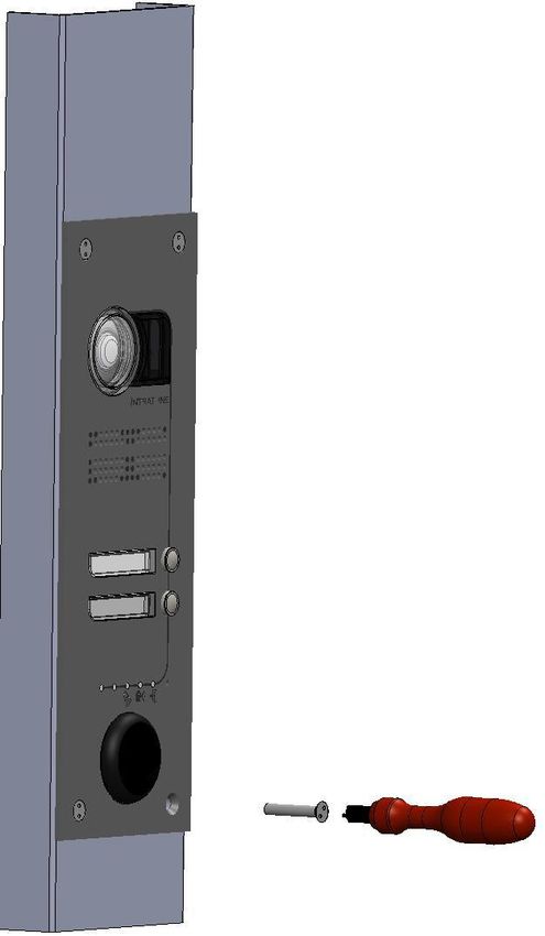
CONTENTS

GENERAL POINTS ----------------------------------------- 1
CONTENTS --------------------------------------------------- 2
DIMENSIONS AND MOUNTING ------------------------ 3
 A)    SURFACE MOUNTED - FIXING ------------------------------------------------ 3
 B)    SURFACE MOUNTED - CLEARANCE ---------------------------------------- 4
 C)    FLUSH MOUNTED - FIXING ----------------------------------------------------- 5
 D)    FLUSH MOUNTED - CLEARANCE--------------------------------------------- 6
 E)    MOUNTED TO A POST - FIXING ------------------------------------------------------ 7
 F)    MOUNTED TO A POST -CLEARANCE --------------------------------------- 8
CABLING ------------------------------------------------------ 9
 A)  CABLING OF INTERCOM AND THE RELAY CARD ----------------------- 9
 B)  CABLING OF AN ENTRANCE OR DOOR FITTED WITH AN
 ELECTRONIC LOCK MECHANISM --------------------------------------------------- 9
 C)  CABLING OF A DOOR FITTED WITH A MAGNETIC LOCK ----------- 10
 D)  ALARM INPUT CABLING ------------------------------------------------------- 10
 E)  CABLING THE ANTENNA ------------------------------------------------------ 10
EQUIPMENT CONFIGURATION ---------------------- 11
 A)  CONFIGURING ON THE WEBSITE WWW.MYINTRATONE.COM -- 11
 B)  PROGRAMMING PHONE NUMBERS WITHOUT GOING ONLINE-- 12
 C)  CONFIGURATION ONLINE AT INTRATONE.COM IN THE
 'MANAGEMENT WEBSITE' TAB ----------------------------------------------------- 12
POST-INSTALLATION CHECK ----------------------- 13
 A)  TESTING THE CABLING OF THE RELAYS AND THE REMOTE
 CONTROLS -------------------------------------------------------------------------------- 13
 B)  CHECKING THE INTERCOM'S SIGNAL RECEPTION STRENGTH 13
 C)  CHECKING AUDIO AND VISIO CALLS WITH YOUR PHONE
 (BEFORE THE INTERCOM IS IN SERVICE) -------------------------------------- 13
TROUBLESHOOTING ----------------------------------- 14
 A)    MOST COMMON PROBLEMS ------------------------------------------------ 14
 B)    PROCEDURE TO RESET THE INTERCOM ------------------------------- 14
CERTIFICATE OF CONFORMITY -------------------- 15

             EN - V233 – 5010 - AA - Fitting and Operation of Villa Intercom
                                                                                 Page 2 / 15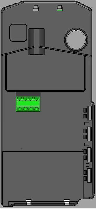
DIMENSIONS AND MOUNTING
 A) SURFACE MOUNTED - FIXING

     1                                 2                               3

   Run cables                                                      SLIDE
                                                                   to close
                                                                     AND
To use the wall                                                     PUSH
plugs provided,                                                     FLAT
  drill Ø 7 mm                                                    against the
                                                                     wall

1 : Fix the mounting bracket.                                           4
2: Hook the intercom onto the
    anchor points.                                               SCREW ON
                                                                 the intercom
3: Slide and push the intercom
flat.
4: Screw.
 Same procedure for mounting the villa
               Intercom.
                                                  Make sure cables are not
       1 to 4 following buttons:                    pinched by the box!
                                                 They might get cut through
                                                     when you tighten.

                                               Remember to run the cable in
                                                    a gooseneck shape
                                                as close as possible to the
                                                         terminal

          EN - V233 – 5010 - AA - Fitting and Operation of Villa Intercom
                                                                            Page 3 / 15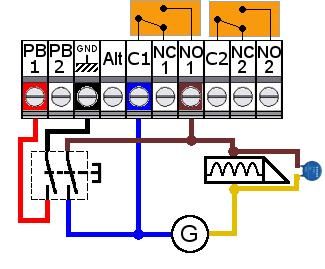
B) SURFACE MOUNTED - SIZE

                           Intercom

                                                       External 3G antenna
     Relay card/HF receiver

       EN - V233 – 5010 - AA - Fitting and Operation of Villa Intercom
                                                                         Page 4 / 15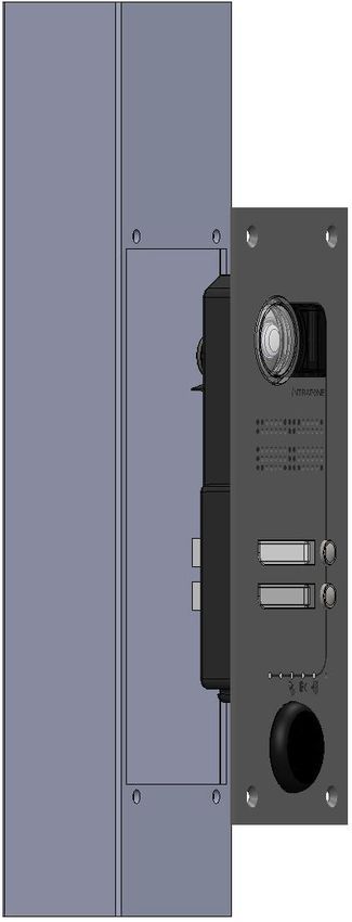
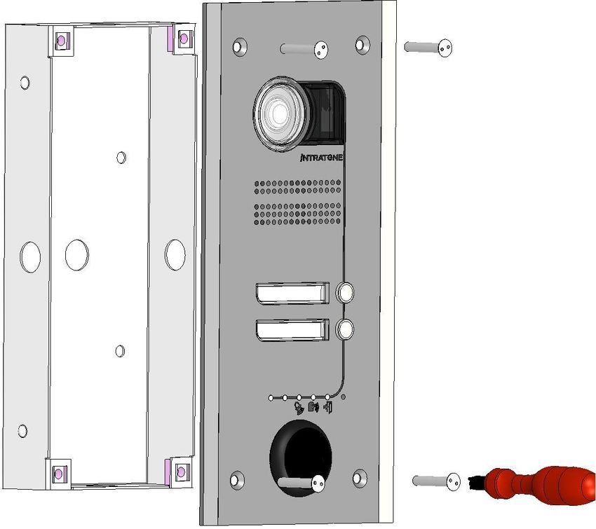
C) FLUSH MOUNTED - FIXING
                                                            WHAT IT LOOKS LIKE ON THE WALL

        Press against
         the casing   3

  Run cables

1: Prepare the recess in the wall to
   receive the casing.
2: Put the casing into the wall and
   fasten.                                                 Make sure cables are not
                                                             pinched by the box!
3: Push the intercom into the casing                         They might get cut
   and screw to fasten.                                       through when you
  Same procedure for mounting the villa Intercom.                  tighten.
         at 3 and 4 the following buttons:
                                                             Remember to run the
                                                             cable in a gooseneck
                                                                     shape
                                                            as close as possible to
                                                                  the terminal

            EN - V233 – 5010 - AA - Fitting and Operation of Villa Intercom
                                                                              Page 5 / 15
D) FLUSH MOUNTED - SIZE

                                                           Intercom
             Casin
               g

            Relay card                                 External 3G antenna

       EN - V233 – 5010 - AA - Fitting and Operation of Villa Intercom
                                                                         Page 6 / 15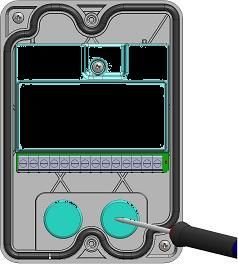
E) MOUNTED TO A POST - FIXING

       1                     Intercom
                                box
                              housing
            2

                               3

                                                               4

1: Cut out a space for the box housing
   in the post.
2: Drill Ø 6 mm hole or tap M5 thread.                       Make sure cables are not
                                                               pinched by the box!
3: Press the intercom into the housing.
                                                                They might get cut
4: Screw it to the post.                                        through when you
    Same procedure for mounting villa Intercom.                      tighten.
         at 3 and 4 the following buttons:

                                                               Remember to run the
                                                               cable in a gooseneck
                                                                       shape
                                                              as close as possible to
                                                                    the terminal

            EN - V233 – 5010 - AA - Fitting and Operation of Villa Intercom
                                                                              Page 7 / 15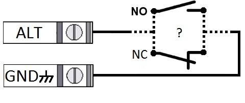
F) MOUNTED TO A POST -SIZE

                                 Intercom

              Relay card                                External 3G antenna

       EN - V233 – 5010 - AA - Fitting and Operation of Villa Intercom
                                                                         Page 8 / 15
CABLING
A) CABLING OF INTERCOM AND THE RELAY CARD
Relay card operating Intercom Antenna
EEN-V-INTER-12 indicator Inside view 3G
External
+ - 3 4 (optional)
3 4
AER
Braid Cente
r
condu
Drill the cabling Coaxial
cor
hole as small as
possible to avoid Antenna
water ingress. HF
868 MHz
(optional)
Twisted pair cable 5 10th 100 meters max
Coaxial
50 ohms
POWER SUPPLY :
As close as possible to the relay card:
12/24 V (AC/DC) - 350/700 mA
B) CABLING OF AN ENTRANCE OR DOOR FITTED WITH AN
ELECTRONIC LOCK MECHANISM
- Wire the push button between the PB and GND terminals
of the relay card
- When the button is pressed, the relay card's relay
supplies power to the lock mechanism for the amount of
time programmed online.
- If the relay card is not functioning, the PB's NO contact
will also supply power to the lock mechanism (ensure
there is a backup power supply)
- At rest, the lock mechanism keeps the door locked,
- When the relay is activated by the relay card, the current
flows and the lock mechanism allows the door to open.
- The power supplied to the electric lock mechanism
must be less than 42 V AC or 60 V DC. If the power
supply voltage exceeds these values, use an
intermediate relay (of the correct capacity) to control
the electric lock.
- Installation of a varistor (blue spot) is essential for
the relay to work properly. This varistor is calibrated
G : Power supply
for 12v.
EN - V233 – 5010 - AA - Fitting and Operation of Villa Intercom
Page 9 / 15C) CABLING OF A DOOR FITTED WITH A MAGNETIC LOCK
- Wire the push button between the PB and GND
terminals of the relay card
- When the button is pressed, the relay card's relay cuts
off power to the magnet for the amount of time
programmed online.
- If the central unit is not functioning, the PB's NC contact
will also cut off power to the magnet.
- At rest, power is supplied to the magnet and it keeps the
door locked,
- When the relay is activated by the central unit, the
magnet's power supply is cut; the magnetic lock opens
the door.
- The power supplied to the electromagnet must be
less than 42 V AC or 60 V DC. If the power supply
voltage exceeds these values, use an intermediate
relay (of the correct capacity) to control the electric
lock.
G : Power supply - Installation of a varistor (blue spot) is essential for
the relay to work properly. This varistor is calibrated
for 12v.
D) ALARM INPUT CABLING
- The alarm contact should be wired between the
Alt and GND terminals of the central unit.
- If the contact is triggered, an email alert is sent
after a pre-programmed period of time has
elapsed
- The type of contact can be NO or NC
- All the alarm settings can be configured on the
website www.myintratone.com in the menu:
'Configure my advanced settings'.
E) CABLING THE ANTENNA
If the intercom is fitted in an area with bad 3G reception, you can connect the external 3G
antenna provided with this kit.
You do not have to use the external antenna.
It allows you to connect to the 3G network wherever reception is best .
1 1: Remove the cable pass-through.
2: Flick the switch down
(Position with external antenna)
3: Screw in the external antenna cable.
4: Position the antenna high up.
2 5: Test by making a call.
EN - V233 – 5010 - AA - Fitting and Operation of Villa Intercom
Page 10 / 15EQUIPMENT CONFIGURATION
A) CONFIGURING ON THE WEBSITE WWW. MYINTRATONE.COM
Most of the programming for the villa intercom is done on the website www.
myintratone.com, To be able to configure your equipment, you need to have your
intercom's 10-digit telephone number. The villa intercom telephone number is given in the
End User's Manual ).
The website myintratone.com has 5 sections:
Add, modify my phone numbers
This menu allows you to enter the phone numbers to be called from the intercom. Up to
10 numbers can be programmed for each button. You can also designate whether the phone
is Visio-compatible or not and set time slots.
Add, modify my remote controls
This menu lets you configure the remote controls that give access. This is also the menu
where you can set your Mobile Key (this feature allows you to give access via your phone).
Finally, if you have the villa intercom '1 call button + 9 button keypad' model, you can set
your keypad codes here.
View log-events
This menu lets you view phone numbers called from the intercom, the remote controls
and Mobile Key, as well as the codes entered if you have the villa intercom '1 callbutton + 9
button keypad' model.
Configure my advanced settings
This menu lets you control several features:
- Adjust the volume on the intercom handset.
- Set the time lapse before the intercom hangs up after opening.
- Set the password to access the website www.myintratone.com
- Email alerts
- Time delay for door opening.
- Time ranges for the intercom, the remote controls and the keypad codes.
- Activate automatic answering (no need to press 0 to speak).
My set-up
This menu lets you designate which entrances are controlled by the relays and you can
also configure a HF (06-0101-EN) kit if you want to add a HF receiver to your installation.
EN - V233 – 5010 - AA - Fitting and Operation of Villa Intercom
Page 11 / 15B) PROGRAMMING PHONE NUMBERS WITHOUT GOING ONLINE
The numbers to call from the intercom can also be programmed on-site using the push
buttons. In order to do this, you must have with you the phones you want to link to the
system.
To program the numbers to call, follow these steps:
Press down for 5 seconds on the call button to be programmed. The LEDs at the
bottom of the call panel will flash quickly, indicating that it is in 'programming mode'.
Call the villa intercom from the primary phone that your client wishes to use without
hiding your number (the villa intercom phone number is given in the End User's
Manual ).
Let it ring 2 or 3 times. The villa intercom is set when the LEDs at the bottom of the
call panel switch off. Hang up.
The villa intercom is now programmed with your client's phone number and you can
press the call button to make sure that it correctly makes the call.
Your client can answer and check straight away that it works, in Visio or audio
depending on the type of phone they have and the type of line.
Press any button on the phone to activate the sound.
Press 1 on your phone to activate relay 1 or press 2 to activate relay 2.
C) CONFIGURATION ONLINE AT INTRATONE.COM IN THE
'MANAGEMENT WEBSITE' TAB
You can program your intercom on the website www.intratone.com in the "management
website" tab. This website lets you combine your management of the villa intercom
equipment with products from the Intratone range.
To create your villa intercom, create a residence and register an entrance such as
'villa intercom' by clicking on the button . Then you can program the numbers by clicking
on 'configure' opposite 'designate label(s)'.
The remote controls provided with the equipment must be registered on the
management website. To do this, you must create an authorisation and add the remote
control in an apartment.
If you have a '1 callbutton + 9 button keypad' model, you can add a code. To do this,
click on 'codes' to the right of the entrance you want to program.
NOTE! The villa intercom that has been registered on the website
intratone.com can no longer be registered on the website
www.myintratone.com and vice versa.
EN - V233 – 5010 - AA - Fitting and Operation of Villa Intercom
Page 12 / 15POST-INSTALLATION CHECK
Once your villa intercom is installed and switched on, you can carry out different
tests to check that it works:
A) TESTING THE CABLING OF THE RELAYS AND THE REMOTE
CONTROLS
The remote controls provided with your villa intercom are already configured to work
when the system is switched on. Press 1 (the button marked I) on the remote control and
see if the entrance linked to relay 1 opens correctly. Do the same thing with button 2 (the
button marked II) if you have 2 entrances to control.
B) CHECKING THE INTERCOM'S SIGNAL RECEPTION STRENGTH
When you turn the power supply to your intercom on for the first time, the 5 LEDs at
the bottom will indicate the strength of signal:
The LEDs blink The number of LEDs indicates the
slowly strength of 3G signal reception.
The number of LEDs indicates the
The LEDs emit a
strength of GSM signal reception
slow double blink
( Visio calls impossible).
Note: if the LEDs on the call panel do neither of these two behaviour, it means you are trying to
install the villa intercom in a place where there is no 3G or GSM network signal.
C) CHECKING AUDIO AND VISIO CALLS WITH YOUR PHONE (BEFORE
THE INTERCOM IS IN SERVICE)
As long as no numbers have been programmed, you can test calling your phone
directly from the intercom. To do this, follow these steps:
Call the villa intercom from your cell phone without hiding your number (the
telephone number of the villa intercom is given in the End User's Manual).
Let it ring 2 or 3 times. The villa intercom is ready when the white LEDs of the
camera light up. Hang up.
Now press the callbutton on the villa intercom (or press any callbutton, if you have a
model with 2, 3 or 4 buttons)
The villa intercom will call you in Visio (if your phone does not have Visio, the villa
intercom will make another call in audio 30 seconds later).
You can answer and check straight away that the Visio feature is working.
Press a button on your phone to activate the sound.
Press 1 on your phone to activate relay 1 or press 2 to activate relay 2.
Note: Your phone's User Manual will tell you if it has the Visio feature.
Before fastening the call panel, carry out a test with a Visio phone so that you can easily determine the
optimum height that will give the best visibility on phones of that type.
EN - V233 – 5010 - AA - Fitting and Operation of Villa Intercom
Page 13 / 15TROUBLESHOOTING
A) MOST COMMON PROBLEMS
What is causing the
What is the fault? How to fix the fault
fault?
The LED on the relay card There is no power supply - Check power supply to the +
does not come on. to the relay card. and - terminals.
The LED on the relay card is Cabling problem between - Check the cabling between
permanently switched on. the intercom and the relay terminals 3 and 4 of the relay card
card. and terminals 3 and 4 of the
intercom.
The door does not open The relay is incorrectly - Check the change of state
when you press on the wired or the door control is between C and T on the relays
remote control or when the faulty. with an ohmmeter where there is a
intercom says 'The door is bridge between the BP input (1 or
open'. 2) and the ground.
- Check the door control without
the central unit (simulate the relay
with wires).
The LEDs on the intercom The intercom is searching - Connect up or reposition the
light up one by one for the GSM/3G network EEN-ANTD-EDGE antenna
continuously. but can't find it. provided with your equipment, in
order to get a better signal.
When you press 1 or 2 on The intercom has not - Check that the 'Voice
the phone, the intercom recognised the button you frequencies' feature is activated
does not say 'The door is pressed on the phone on the phone.
open'. - You may need to press the *
button first, in order for the
intercom to recognise buttons 1
and 2.
When you press the button, There is no number - Configure a number for the
nothing happens. programmed for this button button in question.
B) PROCEDURE TO RESET THE INTERCOM
You can reset the intercom in the event of a problem: this will clear all the data and
settings. Only the remote controls will work after you reset. Procedure to reset:
Remove the black plastic tab on the back of the intercom to access the reset button (to
the right of the green connector).
Press the button (the backlit label goes out) until it lights up again, then release the
button.
Press the button again until the label lights up.
Repeat this operation a third time. The backlit label will flash twice and then you will
see the intercom's GSM/3G signal strength again.
NOTE! ANY PHONE NUMBERS THAT WERE NOT PROGRAMMED VIA THE WEBSITE WILL
BE LOST IN THIS OPERATION!
EN - V233 – 5010 - AA - Fitting and Operation of Villa Intercom
Page 14 / 15CERTIFICATE OF CONFORMITY
V233 – FITTING AND Operation OF #VILLA# Intercom - AA
Page 15 / 15You can also read