Enrange MBT Transmitter - Remote Equipment Controls - March 2013 Part Number: 178-01636-0100-R3 2013 Magnetek Material Handling
←
→
Page content transcription
If your browser does not render page correctly, please read the page content below

Enrange MBT Transmitter
  Remote Equipment Controls

                                        March 2013
                    Part Number: 178-01636-0100-R3
                   © 2013 Magnetek Material Handling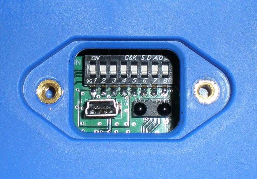
Your New Radio Remote
Thank you for your purchase of Magnetek’s Enrange® brand MBT Radio Remote Equipment
Control. Magnetek has set a whole new standard in radio-remote performance, dependability,
and value with this unique line of handheld transmitters.
If your product ever needs modification or service, please contact one of our representatives at
the following locations:

U.S. Service Information
For questions regarding service or technical information contact:
1.866.MAG.SERV
(1.866.624.7378)

World Headquarters:

Magnetek, Inc.
N49 W13650 Campbell Drive
Menomonee Falls, WI 53051

Telephone:      1.800.288.8178
Website:        www.magnetekmobilehydraulic.com
e-mail:         info@magnetekmh.com

Fax Numbers:
Main:        1.800.298.3503
Sales:       1.262.783.3510
Service:     1.262.783.3508

Magnetek, Inc. has additional satellite locations for Canada and the United States. For more
information, please visit http://www.magnetekmobilehydraulic.com.

©2013 MAGNETEK

All rights reserved. This notice applies to all copyrighted materials included with this product,
including, but not limited to, this manual and software embodied within the product. This manual
is intended for the sole use of the person(s) to whom it was provided, and any unauthorized
distribution of the manual or dispersal of its contents is strictly forbidden. This manual may not be
reproduced in whole or in part by any means whatsoever without the expressed written
permission of MAGNETEK.

                                                                Enrange MBT Transmitter Instruction Manual
                                                                                               March 2013
                                                                                              Page 2 of 45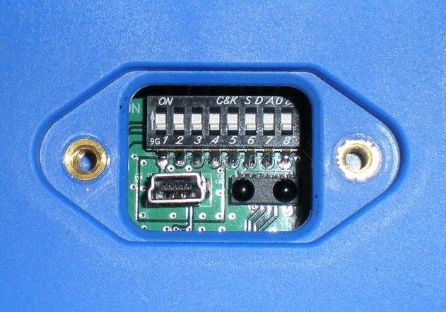
TABLE OF CONTENTS

1.0    INTRODUCTION .................................................................................................................. 5
  1.1    PRODUCT MANUAL SAFETY INFORMATION ............................................................... 5
  1.2    WARNINGS AND CAUTIONS .......................................................................................... 6
2.0    CRITICAL INSTALLATION CONSIDERATIONS ................................................................. 7
  2.1    GENERAL ......................................................................................................................... 7
  2.2    PERSONS AUTHORIZED TO OPERATE RADIO CONTROLLED MACHINERIES ....... 7
  2.3    SAFETY INFORMATION AND RECOMMENDED TRAINING FOR RADIO
  CONTROLLED EQUIPMENT OPERATORS .............................................................................. 8
  2.4    TRANSMITTER UNIT ....................................................................................................... 9
  2.5    PRE-OPERATION TEST .................................................................................................. 9
  2.6    HANDLING BATTERIES................................................................................................. 10
  2.7    OPTIONAL RECHARGEABLE BATTERY CHARGING ................................................. 10
  2.8    BATTERY DISPOSAL..................................................................................................... 10
3.0    MBT TRANSMITTER STANDARD CONFIGURATION AND OPERATION ...................... 11
  3.1    INSTALLING THE BATTERY PACK .............................................................................. 12
    3.1.1     Alkaline Battery Pack (BT127) ................................................................................. 12
    3.1.2     Optional NiMH Rechargeable Battery Pack (BT126) .............................................. 13
    3.1.3     SETTING BATTERY TYPE DIP SWITCHES .......................................................... 14
  3.2    TURNING THE TRANSMITTER ON AND OFF.............................................................. 15
    3.2.1     Turning On the Transmitter (with Standard Status LED Indicator) .......................... 15
    3.2.2     Turning On the Transmitter (with Optional Graphic User Interface Screen) ........... 15
    3.2.3     Pulling In the Machine Stop Relay ........................................................................... 16
    3.2.4     Turning Off the Transmitter ...................................................................................... 16
  3.3    MACHINE STOP SWITCH (For Emergency Stopping Only) .......................................... 16
  3.4    STATUS LED .................................................................................................................. 16
  3.5    OPTIONAL GRAPHIC USER INTERFACE .................................................................... 16
  3.6    NORMAL OPERATING MODE WITH STANDARD STATUS LED ................................ 17
    3.6.1     Watch Dog Indicator (Steady Blinking Status LED)................................................. 17
    3.6.2     Switch Change Indicator (Rapidly Blinking Status LED) ......................................... 17
    3.6.3     Low Battery Level Indicator (Blinking Red Status LED) .......................................... 17
  3.7    NORMAL OPERATING MODE WITH OPTIONAL GRAPHIC USER INTERFACE ....... 17
    3.7.1     Watch Dog Indicator (Spinning Arrow) .................................................................... 18
    3.7.2     Command Confirmation ........................................................................................... 18
    3.7.3     Battery Life Indicator ................................................................................................ 18
    3.7.4     Signal Strength Indicator ......................................................................................... 18
    3.7.5     Two-Way Feedback System .................................................................................... 18
  3.8    JOYSTICKS AND PADDLES/LEVERS .......................................................................... 18
  3.9    ROTARY SELECTOR SWITCH ..................................................................................... 19
  3.10      AUXILIARY SWITCHES .............................................................................................. 19
4.0    TRANSMITTER SETUP ..................................................................................................... 20
  4.1    TRANSMITTER SETUP SETTINGS WITH STANDARD STATUS LED ........................ 20
    4.1.1     RF Channel Setting Override ................................................................................... 20
    4.1.2     RF Channel Setting Selection.................................................................................. 20
    4.1.3     IR Configuration Receiver ........................................................................................ 22
       4.1.3.1     IR Configuration Receiver On Transmitters Equipped with Separate
       Power/Status and Battery LED Indicators .......................................................................... 22
       4.1.3.2     IR Configuration Receiver On Transmitters Equipped with Single Status/Battery
       LED Indicator ...................................................................................................................... 23
  4.2    USING THE TRANSMITTER IN SETUP MODE (WITH OPTIONAL GRAPHIC USER
  INTERFACE).............................................................................................................................. 24
    4.2.1     Entering Setup Mode ............................................................................................... 24
    4.2.2     Adjusting Settings in Setup Mode ............................................................................ 24
       4.2.2.1     Access Code..................................................................................................... 24

                                                                                         Enrange MBT Transmitter Instruction Manual
                                                                                                                        March 2013
                                                                                                                       Page 3 of 45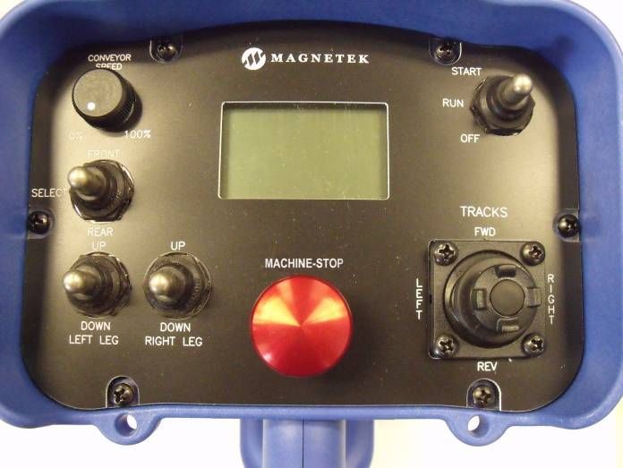
4.2.2.2       Channel Select ................................................................................................. 25
      4.2.2.3       User Code......................................................................................................... 25
      4.2.2.4       Transmitter Timeout.......................................................................................... 25
      4.2.2.5       Backlight Timeout ............................................................................................. 25
      4.2.2.6       Password Enable .............................................................................................. 26
      4.2.2.7       Change Password ............................................................................................ 26
      4.2.2.8       IR Configuration Receiver ................................................................................ 26
      4.2.2.9       Exit Without Save ............................................................................................. 27
      4.2.2.10 Exit With Save .................................................................................................. 27
5.0   OPTIONAL PROGRAMMING WITH RCP.......................................................................... 28
  5.1    ACCESS CODES............................................................................................................ 28
  5.2    CHANGING RECIEVER ACCESS CODES.................................................................... 28
  5.3    CONNECTING THE MBT TO A COMPUTER ................................................................ 29
  5.4    PROGRAMMING WITH RCP ......................................................................................... 30
    5.4.1    MBT Configuration Pages ........................................................................................ 32
    5.4.2    Saving, Downloading, and Reading the Programs and Other RCP Software
    Functions ................................................................................................................................ 37
6.0   TRANSMITTER CHANNEL CONFIGURATION SETTINGS ............................................. 39
  6.1    FCC STATEMENTS........................................................................................................ 39
  6.2    CHANNEL AND FREQUENCY DESIGNATIONS BY COUNT....................................... 40
  6.3    OPTIONAL FREQUENCIES AND CHANNELS ............................................................. 41
    6.3.1    900 MHz: FHSS ....................................................................................................... 41
    6.3.2    2.4 GHZ: FHSS ........................................................................................................ 41
    6.3.3    433 MHz Telemotive Legacy Channel Set: TMS and TDMA .................................. 41
7.0   OPTIONAL CAN BUS TETHER FEATURE ....................................................................... 42
  7.1    INSTALLATION OF TETHER CABLE ............................................................................ 42
  7.2    OPERATION OF TRANSMITTER IN TETHER MODE .................................................. 42
  7.3    RETURNING TRANSMITTER TO WIRELESS MODE .................................................. 42
  7.4    CAN CONNECTOR RECEPTACLE PIN-OUT DETAILS ............................................... 43
8.0    GENERAL TROUBLESHOOTING .................................................................................... 44
  8.1    TROUBLESHOOTING OPTIONAL TETHER OPERATION ........................................... 45
  8.2    ASSEMBLY AND REPLACEMENT PARTS ................................................................... 45

                                                                                           Enrange MBT Transmitter Instruction Manual
                                                                                                                          March 2013
                                                                                                                         Page 4 of 45
1.0 INTRODUCTION
Thank you for your purchase of Magnetek’s Enrange® brand MBT Radio Remote Equipment Control.
These instructions are to be used as a reference for personnel operating the Enrange® brand MBT Radio
®
Remote Equipment Control and the equipment that this Enrange brand MBT Radio Remote Equipment
Control is attached to.
The user of these instructions should have basic knowledge in the handling of electronic equipment.
1.1 PRODUCT MANUAL SAFETY INFORMATION
Magnetek, Inc. (Magnetek) offers a broad range of radio remote control products, control products and
adjustable frequency drives, and industrial braking systems for overhead material handling applications.
This manual has been prepared by Magnetek to provide information and recommendations for the
installation, use, operation and service of Magnetek’s material handling products and systems (Magnetek
Products). Anyone who uses, operates, maintains, services, installs or owns Magnetek Products should
know, understand and follow the instructions and safety recommendations in this manual for Magnetek
Products.
The recommendations in this manual do not take precedence over any of the following requirements relating
to proper equipment operation:
Instructions, manuals, and safety warnings of the manufacturers of the equipment where the radio
system is used,
Plant safety rules and procedures of the employers and the owners of facilities where the Magnetek
Products are being used,
Regulations issued by the Occupational Health and Safety Administration (OSHA),
Applicable local, state or federal codes, ordinances, standards and requirements, or
Safety standards and practices for the specific industry.
This manual does not include or address the specific instructions and safety warnings of these
manufacturers or any of the other requirements listed above. It is the responsibility of the owners, users and
operators of the Magnetek Products to know, understand and follow all of these requirements. It is the
responsibility of the owner of the Magnetek Products to make its employees aware of all of the above listed
requirements and to make certain that all operators are properly trained. No one should use Magnetek
Products prior to becoming familiar with and being trained in these requirements.
WARRANTY INFORMATION
FOR INFORMATION ON MAGNETEK’S PRODUCT WARRANTIES BY PRODUCT TYPE, PLEASE VISIT
WWW.MAGNETEKMOBILEHYDRAULIC.COM.
Enrange MBT Transmitter Instruction Manual
March 2013
Page 5 of 45
1.2      WARNINGS AND CAUTIONS

Throughout this document WARNING and CAUTION statements have been deliberately placed
to highlight items critical to the protection of personnel and equipment.

WARNING – A warning highlights an essential operating or maintenance procedure,
practice, etc. which if not strictly observed, could result in injury or death of personnel, or
long term physical hazards. Warnings are highlighted as shown below:

                                                   WARNING

CAUTION – A caution highlights an essential operating or maintenance procedure,
practice, etc. which if not strictly observed, could result in damage to, or destruction of
equipment, or loss of functional effectiveness. Cautions are highlighted as shown below:

                                                    CAUTION

WARNINGS AND CAUTIONS SHOULD NEVER BE DISREGARDED.

The safety rules in this section are not intended to replace any rules or regulations of any applicable local,
state, or federal governing organizations. Always follow your local lockout and tagout procedure when
maintaining any radio equipment. The following information is intended to be used in conjunction with other
rules or regulations already in existence. It is important to read all of the safety information contained in this
section before installing or operating the Radio Control System.

                                                                        Enrange MBT Transmitter Instruction Manual
                                                                                                       March 2013
                                                                                                      Page 6 of 45
2.0     CRITICAL INSTALLATION CONSIDERATIONS

                                                 WARNING
PRIOR TO INSTALLATION AND OPERATION OF THIS EQUIPMENT, READ AND DEVELOP AN
UNDERSTANDING OF THE CONTENTS OF THIS MANUAL AND THE OPERATION MANUAL OF THE
EQUIPMENT OR DEVICE TO WHICH THIS EQUIPMENT WILL BE INTERFACED. FAILURE TO FOLLOW
THIS WARNING COULD RESULT IN SERIOUS INJURY OR DEATH AND DAMAGE TO EQUIPMENT.

ALL EQUIPMENT MUST HAVE A MAINLINE CONTACTOR INSTALLED AND ALL TRACKED CRANES,
HOISTS, LIFTING DEVICES AND SIMILAR EQUIPMENT MUST HAVE A BRAKE INSTALLED. FAILURE
TO FOLLOW THIS WARNING COULD RESULT IN SERIOUS INJURY OR DEATH AND DAMAGE TO
EQUIPMENT.

AN AUDIBLE AND/OR VISUAL WARNING MEANS MUST BE PROVIDED ON ALL REMOTE
CONTROLLED EQUIPMENT AS REQUIRED BY CODE, REGULATION, OR INDUSTRY STANDARD.
THESE AUDIBLE AND/OR VISUAL WARNING DEVICES MUST MEET ALL GOVERNMENTAL
REQUIREMENTS. FAILURE TO FOLLOW THIS WARNING COULD RESULT IN SERIOUS INJURY OR
DEATH AND DAMAGE TO EQUIPMENT.

FOLLOW YOUR LOCAL LOCKOUT TAGOUT PROCEDURE BEFORE MAINTAINING ANY REMOTE
CONTROLLED EQUIPMENT. ALWAYS REMOVE ALL ELECTRICAL POWER FROM THE CRANE,
HOIST, LIFTING DEVICE OR SIMILAR EQUIPMENT BEFORE ATTEMPTING ANY INSTALLATION
PROCEDURES. DE-ENERGIZE AND TAGOUT ALL SOURCES OF ELECTRICAL POWER BEFORE
TOUCH-TESTING ANY EQUIPMENT. FAILURE TO FOLLOW THIS WARNING COULD RESULT IN
SERIOUS INJURY OR DEATH AND DAMAGE TO EQUIPMENT.

THE DIRECT OUTPUTS OF THIS PRODUCT ARE NOT DESIGNED TO INTERFACE DIRECTLY TO TWO
STATE SAFETY CRITICAL MAINTAINED FUNCTIONS, I.E., MAGNETS, VACUUM LIFTS, PUMPS,
EMERGENCY EQUIPMENT, ETC. A MECHANICALLY LOCKING INTERMEDIATE RELAY SYSTEM
WITH SEPARATE POWER CONSIDERATIONS MUST BE PROVIDED. FAILURE TO FOLLOW THIS
WARNING COULD RESULT IN SERIOUS INJURY OR DEATH OR DAMAGE TO EQUIPMENT.

2.1     GENERAL
Radio controlled equipment operates in several directions. Quite frequently, the equipment is operated in
areas where people are working in close proximity to the material handling equipment. The operator must
exercise extreme caution at all times. Workers must constantly be alert to avoid accidents. The following
recommendations have been included to indicate how careful and thoughtful actions may prevent injuries,
damage to equipment, or even save a life.

2.2     PERSONS AUTHORIZED TO OPERATE RADIO CONTROLLED MACHINERIES
Only properly trained persons designated by management should be permitted to operate radio controlled
equipment.

Radio controlled equipment should not be operated by any person who cannot read or understand signs,
notices, and operating instructions that pertain to the equipment.

Radio controlled equipment should not be operated by any person with insufficient eyesight or hearing or by
any person who may be suffering from a disorder or illness, is taking any medication that may cause loss of
equipment control, or is under the influence of alcohol or drugs.

                                                                    Enrange MBT Transmitter Instruction Manual
                                                                                                   March 2013
                                                                                                  Page 7 of 45
2.3 SAFETY INFORMATION AND RECOMMENDED TRAINING FOR RADIO
CONTROLLED EQUIPMENT OPERATORS
Anyone being trained to operate radio controlled equipment should possess as a minimum the following
knowledge and skills before using the radio controlled equipment.
The operator should:
have knowledge of hazards pertaining to equipment opera¬tion
have knowledge of safety rules for radio controlled equipment
have the ability to judge distance of moving objects
know how to properly test prior to operation
be trained in the safe operation of the radio transmitter as it pertains to the crane, hoist, lifting
device or other material handling equipment being operated
have knowledge of the use of equipment warning lights and alarms
have knowledge of the proper storage space for a radio control transmitter when not in use
be trained in transferring a radio control transmitter to another person
be trained how and when to report unsafe or unusual operating condi¬tions
test the transmitter emergency stop and all warning devices prior to operation; testing should be
done on each shift, without a load
be thoroughly trained and knowledgeable in proper and safe operation of the crane, hoist, lifting
device, or other material handling equipment that utilizes the radio control
know how to keep the operator and other people clear of lifted loads and to avoid “pinch” points
continuously watch and monitor status of lifted loads
know and follow cable and hook inspection procedures
know and follow the local lockout and tagout procedures when servicing radio controlled equipment
know and follow all applicable operating and maintenance manuals, safety procedures, regulatory
requirements, and industry standards and codes
The operator shall not:
lift or move more than the rated load
operate the material handling equipment if the direction of travel or function engaged does not
agree with what is indicated on the controller
use the crane, hoist or lifting device to lift, support or transport people
lift or carry any loads over people
operate the crane, hoist or lifting device unless all persons, including the operator, are and remain
clear of the supported load and any potential pinch points
operate a crane, hoist or lifting device when the device is not centered over the load
operate a crane, hoist or lifting device if the chain or wire rope is not seated properly in the
sprockets, drum or sheave
operate any damaged or malfunctioning crane, hoist, lifting device or other material handling
equipment
change any settings or controls without authorization and proper training
remove or obscure any warning or safety labels or tags
leave any load unattended while lifted
Enrange MBT Transmitter Instruction Manual
March 2013
Page 8 of 45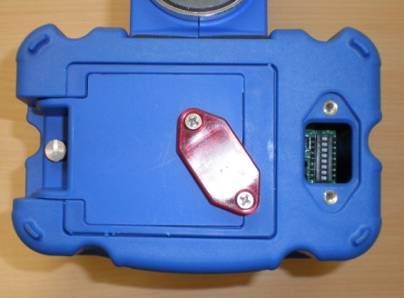
leave power on the radio controlled equipment when the equipment is not in operation
operate any material handling equipment using a damaged controller because the unit may be
unsafe
operate manual motions with other than manual power
operate radio controlled equipment when low battery indicator is on
WARNING
THE OPERATOR SHOULD NOT ATTEMPT TO REPAIR ANY RADIO CONTROLLER. IF ANY PRODUCT
PERFORMANCE OR SAFETY CONCERNS ARE OBSERVED, THE EQUIPMENT SHOULD
IMMEDIATELY BE TAKEN OUT OF SERVICE AND BE REPORTED TO THE SUPERVISOR. DAMAGED
AND INOPERABLE RADIO CONTROLLER EQUIPMENT SHOULD BE RETURNED TO MAGNETEK FOR
EVALUATION AND REPAIR. FAILURE TO FOLLOW THIS WARNING COULD RESULT IN SERIOUS
INJURY OR DEATH AND DAMAGE TO EQUIPMENT.
2.4 TRANSMITTER UNIT
Transmitter switches should never be mechanically blocked ON or OFF. When not in use, the operator
should turn the transmitter OFF. A secure storage space should be provided for the transmitter unit, and the
transmitter unit should always be placed there when not in use. This precaution will help prevent
unauthorized people from operating the material handling equipment.
Spare transmitters should be stored in a secure storage space and only removed from the storage space
after the current transmitter in use has been turned OFF, taken out of the service area and secured.
2.5 PRE-OPERATION TEST
At the start of each work shift, or when a new operator takes control of the equipment, operators should do,
as a minimum, the following steps before operation of equipment:
Test all warning devices.
Test all direction and speed controls.
Test all functions.
Test the transmitter emergency stop.
Enrange MBT Transmitter Instruction Manual
March 2013
Page 9 of 45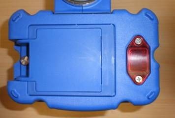
2.6      HANDLING BATTERIES

                                                   WARNING
KNOW AND FOLLOW PROPER BATTERY HANDLING, CHARGING AND DISPOSAL PROCEDURES.
IMPROPER BATTERY PROCEDURES CAN CAUSE BATTERIES TO EXPLODE OR DO OTHER
SERIOUS DAMAGE. FAILURE TO FOLLOW THIS WARNING COULD RESULT IN SERIOUS INJURY OR
DEATH AND DAMAGE TO EQUIPMENT.

Use only batteries approved by Magnetek for the specific product.

Do not dispose of a battery pack in fire; it may explode.

Do not attempt to open the battery pack.

Do not short circuit the battery.

Keep the battery pack environment cool during charging operation and storage (i.e., not in direct sunlight or
close to a heating source).

2.7      OPTIONAL RECHARGEABLE BATTERY CHARGING
For those transmitters equipped with battery chargers, please familiarize all users with the instructions of the
charger before attempting to use.

Do not attempt to charge non-rechargeable battery packs.

Avoid charging partially discharged rechargeable batteries to help prolong battery cycle life.

Do not charge batteries in a hazardous environment.

Keep the battery pack environment cool during charging (i.e., not in direct sunlight or close to a heating
source).

Do not short the charger.

Do not attempt to charge a damaged battery.

Use only Magnetek Enrange approved chargers for the appropriate battery pack.

Do not attempt to use a battery that is leaking, swollen or corroded.

Charger units are not intended for outdoor use. Use only indoors.

2.8      BATTERY DISPOSAL
Before disposing of batteries consult local and governmental regulatory requirements for proper disposal
procedure.

                                                                        Enrange MBT Transmitter Instruction Manual
                                                                                                       March 2013
                                                                                                     Page 10 of 45
3.0 MBT TRANSMITTER STANDARD CONFIGURATION AND OPERATION
WARNING
BEFORE OPERATING THE TRANSMITTER, FAMILIARIZE YOURSELF WITH ALL SAFETY
INFORMATION IN THIS MANUAL, THE CORRESPONDING RECEIVER SYSTEM MANUAL,
APPROPRIATE MANUAL SUPPLEMENTS AND ANY OTHER LOCAL, STATE, OR FEDERAL RULES OR
REGULATIONS ALREADY IN EXISTENCE. FAILURE TO FOLLOW THIS WARNING COULD RESULT IN
SERIOUS INJURY OR DEATH AND DAMAGE TO EQUIPMENT.
Figure 1: Typical MBT Configuration.
Enrange MBT Transmitter Instruction Manual
March 2013
Page 11 of 453.1 INSTALLING THE BATTERY PACK
Prior to utilizing the MBT transmitter, the battery pack must be installed (unless the unit is being
utilized with the optional tether feature - then the battery pack is optional).
3.1.1 Alkaline Battery Pack (BT127)
The MBT comes standard with a battery pack (BT127) that holds three disposable AA alkaline
batteries.
Figure 2: BT127 Battery Pack
To change the alkaline batteries in the battery pack, separate the inner tray from the outer
housing (see Figure 2) and replace all the batteries with new ones.
Figure 3: Separated Alkaline Battery Pack
When reinserting the tray into the outer housing, make sure the grooves in the inner tray align
with the slides in the outer housing. When placing the battery pack into the MBT battery pocket,
orient the battery pack so that the sticker is facing out (see Figure 4).
Figure 4: Installation of Battery Pack into MBT transmitter
After installing the battery pack, install the battery cover over the battery and secure by tightening
the thumbscrew at the end of the battery cover (see Figure 5).
Enrange MBT Transmitter Instruction Manual
March 2013
Page 12 of 45Figure 5: Installation of Battery Cover
NOTE: For the battery level indicator on the MBTs equipped with the standard status LED or the
optional graphic user interface, the battery type dip switch settings need to be set for the battery
pack being used in order to display the correct low battery level indication. See Section 3.1.3 for
details on setting the battery type dip switches.
3.1.2 Optional NiMH Rechargeable Battery Pack (BT126)
NOTE: If using the optional rechargeable battery pack BT126, review and become familiar with
the rechargeable battery charger manual prior to use.
The rechargeable battery pack BT126 is a sealed battery pack that has no user serviceable
components within the battery pack.
Figure 6: BT126 Battery Pack
The rechargeable battery pack BT126 is shipped from the factory with a minimal charge and will
need to be charged prior to use for the first time with the specified charger.
NOTE: When utilizing the optional tether mode on the MBT transmitter, the battery packs will not
be recharged from the tether power feed. The rechargeable battery pack only can be recharged
using the specified charger.
When placing the battery pack into the MBT battery pocket, orient the battery pack so that the
sticker is facing out (see Figure 4).
After installing the battery pack, install the battery cover over the battery and secure by tightening
the thumbscrew at the end of the battery cover (see Figure 5).
NOTE: For the battery level indicator on the MBTs equipped with the standard status LED or the
optional graphic user interface, the battery type dip switch settings need to be set for the battery
pack being used in order to display the correct low battery level indication. See Section 3.1.3 for
details on setting the battery type dip switches.
Enrange MBT Transmitter Instruction Manual
March 2013
Page 13 of 453.1.3 SETTING BATTERY TYPE DIP SWITCHES
For proper indication of the battery level on the MBT transmitters, the battery type dip switch
settings need to be set for the battery pack being used in the transmitter.
NOTE: The dip switch settings are set at the factory for the battery type ordered with the system.
These settings will need to be changed only if the battery type changes.
The dip switches are accessed through the USB/IR cover on the bottom of the MBT transmitter
(see Figure 7).
Figure 7: USB/IR Cover Location and Cover Removal
Use the following table to properly set the dip switches for the correct battery type (see Figure 8
for dip switch view):
Battery P/N Battery Type Dip switch 1 Dip switch 2
BT127-0 4.5V Alkaline Off Off
BT126-0 3.6V NiMH Off On
Figure 8: Dip switch block as viewed through USB/IR port
NOTE: The dip switch block switches are oriented so that the OFF position is next to the number
designator and the ON position is up or away from the number designator.
Enrange MBT Transmitter Instruction Manual
March 2013
Page 14 of 453.2 TURNING THE TRANSMITTER ON AND OFF
The MBT uses both a three position toggle switch labeled OFF-ON-START and a Machine Stop
switch to turn the transmitter on or off.
Figure 9: Machine Stop Switch and OFF-ON-START toggle
3.2.1 Turning On the Transmitter (with Standard Status LED Indicator)
First, the Machine Stop switch must be in the raised position (pulled out). Next, push the OFF-
ON-START toggle switch to the START position and release it once the Status LED lights up as a
solid green color. Following the Status LED turning on and illuminating green, the unit will
perform a routine initialization.
During initialization, the MBT scans for any switches or motions that may be on during power up.
If any switches or motions are on, the failure will be displayed as a solid red Status LED, and then
the MBT will power itself down.
After a successful initialization, the MBT will enter normal operation mode and display the normal
operating status LED indications. See Section 3.6 for more information on the normal operation
mode with standard status LED.
3.2.2 Turning On the Transmitter (with Optional Graphic User Interface Screen)
First, the Machine Stop switch must be in the raised position (pulled out). Next, push the OFF-
ON-START toggle switch to the START position and release it once the Magnetek logo appears
on the LCD screen. Following the logo screen, the unit will perform a routine initialization.
During initialization, the MBT scans for any switches or motions that may be on during power up.
If any switches or motions are on, the failure will be displayed on the screen, and then the MBT
will power itself down.
After a successful initialization, the MBT will enter the Normal Operation Mode and display the
normal operating screen. See Section 3.7 for more information on the Normal Operation Mode
with Optional Graphic User Interface.
NOTE: Holding the OFF-ON-START toggle in the START position for more than 5 seconds will
put the device into Setup Mode. For normal use release the START toggle once the Magnetek
logo appears. See Section 4.2 for more information on the Setup Mode.
Enrange MBT Transmitter Instruction Manual
March 2013
Page 15 of 453.2.3 Pulling In the Machine Stop Relay
Once the MBT has been turned on (as described in Sections 3.2.1 or 3.2.2) and in the Normal
Operating Mode, the Machine Stop relay in the receiver can be pulled in by pushing the OFF-ON-
START toggle switch to the START position and then releasing.
NOTE: You must release the OFF-ON-START switch to the ON position after the unit is powered
up, then push to the START position a second time to pull in the Machine Stop relay in the
receiver.
3.2.4 Turning Off the Transmitter
The transmitter can be turned off by pressing the OFF-ON-START toggle switch down to the OFF
position. Once turned off, the MLC relay in the receiver is immediately opened.
NOTE: If the unit has a standard status LED, it will illuminate solid red during the transmitter’s
power down process. Once the power down process is complete, the transmitter will turn off and
the status LED will not be on.
NOTE: Depressing the Machine Stop switch will also turn the transmitter off and open the
Machine Stop relay in the receiver. See Section 3.3 for more information on the Machine Stop
switch.
3.3 MACHINE STOP SWITCH (For Emergency Stopping Only)
When the Machine Stop switch is depressed, the Machine Stop relay in the receiver is
immediately opened.
Under normal operating conditions, the Machine Stop switch must be in the raised position or the
transmitter and system will not operate.
NOTE: The Machine Stop Switch is to be used for emergency stopping only, not for normal
system shut down.
3.4 STATUS LED
The standard MBT transmitter includes a status LED to let the operator know that the unit is
functioning and if the battery level is low.
3.5 OPTIONAL GRAPHIC USER INTERFACE
The optional LCD screen located at the center of the device provides visual information during the
operation of the MBT transmitter. It is used to change configuration settings, confirm commands
being operated, provide two-way feedback, and display transmitter diagnostic information such as
battery life and signal strength.
The optional graphic user interface replaces the standard status LED when ordered.
Enrange MBT Transmitter Instruction Manual
March 2013
Page 16 of 453.6 NORMAL OPERATING MODE WITH STANDARD STATUS LED
In normal operating mode, the MBT utilizes the status LED to communicate the watch dog timer
within the CPU of the transmitter and when the battery level is low.
3.6.1 Watch Dog Indicator (Steady Blinking Status LED)
The blinking LED represents the watch dog timer within the CPU of the unit.
NOTE: The LED should be continuously blinking at all times. If the LED is not blinking the
transmitter will need to be rebooted to operate properly.
3.6.2 Switch Change Indicator (Rapidly Blinking Status LED)
When a switch is actuated or a switch status changes, the status LED will blink rapidly during the
change.
NOTE: If a joystick, rotary switch or auxiliary switch is held in position or latched, the status LED
will return to the steady watch dog indicator blinking state.
3.6.3 Low Battery Level Indicator (Blinking Red Status LED)
The status LED will turn red when the battery level drops below 10%. The status LED will
continue blinking for the watch dog indicator and switch change indicator status.
NOTE: If using an optional battery pack that is different than what the unit was shipped from the
factory with, the low battery level indicator will be inaccurate unless the dip switch settings are set
to the correct battery type being used. See Section 3.1.3 for details to properly set the dip
switches.
3.7 NORMAL OPERATING MODE WITH OPTIONAL GRAPHIC USER INTERFACE
In normal operating mode, the MBT displays real time information relating to the operation of the
transmitter on the graphic user interface. Information may include Command Confirmation,
Battery Life, Signal Strength, Two-Way Feedback, etc.
Figure 10: Normal operating screen on graphic user interface
Enrange MBT Transmitter Instruction Manual
March 2013
Page 17 of 453.7.1 Watch Dog Indicator (Spinning Arrow)
The spinning arrow represents the watch dog timer within the CPU of the unit.
NOTE: The arrow should be continuously spinning at all times. If the arrow is not spinning, the
transmitter needs to be rebooted to operate properly.
3.7.2 Command Confirmation
Each time the user operates a control on the transmitter, a message will be displayed on the
graphic user interface screen confirming what is being operated.
For example, if the second paddle is moved to its 4th position in the UP direction the display will
show ‘MTN2 D1 SP=4’. This translates to ‘Motion 2, Direction 1, Speed 4’.
3.7.3 Battery Life Indicator
Remaining battery life is displayed in the bottom left hand corner of the graphic user interface
screen.
Battery life is displayed in 5% increments.
NOTE: If using an optional battery pack that is different than what the unit was shipped from the
factory with, the battery life indicator will be inaccurate unless the dip switch settings are set to
the correct battery type being used. See Section 3.1.3 for details to properly set the dip switches.
3.7.4 Signal Strength Indicator
The Signal Strength Indicator is only available in systems equipped for Two-Way feedback
(systems utilizing the 433 MHz frequency band do not have Two-Way feedback available). For
such systems, Signal Strength is displayed at the bottom right hand corner of the graphic user
interface screen.
Signal Strength is displayed in 5% increments.
NOTE: On 433 MHz systems, the signal strength indicator will show minimum signal strength
regardless of the actual signal strength (systems utilizing the 433 MHz frequency band do not
have Two-Way feedback).
3.7.5 Two-Way Feedback System
This option allows the user to view various parameters that may be important to the operation of
the equipment on the graphic user interface display screen.
Parameters such as engine RPM, the torque or speed of a drive, temperature, current, or any
other useful values can be sent from the receiver and displayed on the transmitter.
NOTE: Systems utilizing the 433 MHz frequency band do NOT have Two-Way feedback
available.
3.8 JOYSTICKS AND PADDLES/LEVERS
To activate the desired motor functions, operate the Joystick or Paddle/Lever that corresponds to
the desired motion.
To activate higher speed functions for those transmitter models so equipped, operate the Joystick
or Paddle/Lever further to activate the desired speed.
Enrange MBT Transmitter Instruction Manual
March 2013
Page 18 of 453.9 ROTARY SELECTOR SWITCH
The rotary selector switch can be used to select various modes of operation.
A rotary switch can have 2 to 12 positions to select from.
3.10 AUXILIARY SWITCHES
These switches activate special function relays that control items such as grab attachments,
magnets, lights, etc.
The auxiliary switches can be momentary or latched.
Enrange MBT Transmitter Instruction Manual
March 2013
Page 19 of 454.0 TRANSMITTER SETUP
The transmitter may have settings changed one of four ways.
For units without the optional graphic user interface, the built-in dip switch block can adjust the
RF channel, RF Channel Setting Override function, and the battery type. The RF channel and
access code can be programmed using the IR configuration link with a compatible receiver. All
other settings can only be changed at the factory or with the optional RCP software.
For units with the optional graphic user interface, the Setup Mode can be used to edit
configuration settings such as: Access Code, Channel Select, User Code, Transmitter Time Out,
Backlight Time Out, Password Enable, Change Password, and more. The settings can also be
changed with the optional RCP software.
NOTE: The IR configuration receiver link can adjust settings on both types of units (with and
without the optional graphic user interface), but on units without the optional display the saved
channel is only used if the override dip switch is set to ON. If the override dip switch is set to
OFF, the dip switch settings set the RF channel.
NOTE: The optional RCP software can adjust settings on both types of units (with and without
the optional graphic user interface) but on units without the optional display, the saved channel is
only used if the override dip switch is set to ON. If the override dip switch is set to OFF, the dip
switch settings set the RF channel.
4.1 TRANSMITTER SETUP SETTINGS WITH STANDARD STATUS LED
There are three settings that can be adjusted using the dip switch block: the battery life indication
setting, the RF Channel Setting Override setting, and the RF Channel setting. In addition, the
access code and channel can be changed using the IR configuration receiver link with a
compatible receiver (contact the factory to determine if your receiver is compatible).
The Battery Life Indication setting can be set for the appropriate battery type using dip switch
positions 1 and 2; this is detailed in Section 3.1.3. The RF Channel Setting Override, the RF
Channel Setting Selection, and the IR Configuration are detailed in the following sections.
4.1.1 RF Channel Setting Override
The dip switch block can enable or disable the RF channel setting dip switch override. Dip switch
position number 3 enables the channel from memory function, which enables the transmitter to
utilize the channel setting that was set up with the optional RCP software in the transmitter’s
memory (instead of normally overwriting the channel settings with the dip switch settings in
standard status LED equipped transmitters) or to use the channel that was set up using the IR
configuration receiver option. This dip switch is located on the same block used for battery life
indication and is visible through the USB/IR window (see Figure 11). To set the RF channel
setting override, reference Figure 12 for dip switch settings for the override function.
4.1.2 RF Channel Setting Selection
The dip switch block can also set the RF channel setting. This dip switch block is the same block
used for RF channel setting override and battery life indication. The dip switch block is visible
through the USB/IR window (see Figure 11).
Enrange MBT Transmitter Instruction Manual
March 2013
Page 20 of 45Figure 11: Dip switch block as viewed through USB/IR port
NOTE: The dip switch block switches are oriented so that the Off position is next to the number
designator and the On position is up or away from the number designator.
Regardless of which radio frequency the transmitter was equipped with the RF channel dip switch
settings are the same. Refer to Sections 6.2 and 6.3 for details on the specific RF channel
details for the radio frequency that the transmitter is equipped with.
The following figure details the dip switch positions for each RF channel.
Figure 12: Dip switch positions for RF channel selection
Enrange MBT Transmitter Instruction Manual
March 2013
Page 21 of 45The dip switch settings will take effect upon the next power cycle of the transmitter.
NOTE: If using the optional RCP software on transmitters NOT equipped with the optional
graphic user interface, the channel settings will read from the dip switch positions and not from
memory when the channel from memory override function is not enabled. The RF channel set
by the optional RCP software will not be used unless the memory override dip switch is set to ON.
When the RF channel from memory override is NOT enabled, the dip switch positions set the RF
channel used by the transmitter.
NOTE: If using the IR configuration receiver function on transmitters NOT equipped with the
optional graphic user interface, the channel settings will read from the dip switch positions and
not from memory when the channel from memory override function is not enabled. The RF
channel set by the IR configuration receiver function will not be used unless the memory override
dip switch is set to ON. When the RF channel from memory override is NOT enabled, the dip
switch positions set the RF channel used by the transmitter.
NOTE: The transmitters equipped with the optional graphic user interface will read channel
settings from memory and will not respond to dip switch changes for the channel setup. Only the
dip switches for the battery life indication are functional on graphic user interface equipped
transmitters.
4.1.3 IR Configuration Receiver
IR Cfg Recv function allows the transmitter to link, using IR, to a compatible receiver (contact the
factory to determine if your receiver is compatible) and automatically set up the channel and
access code to match the linked compatible receiver.
NOTE: If using the IR configuration receiver function on transmitters NOT equipped with the
optional graphic user interface, the channel settings will read from the dip switch positions and
not from memory when the channel from memory override function is not enabled. The RF
channel set by the IR configuration receiver function will not be used unless the memory override
dip switch is set to ON. When the RF channel from memory override is NOT enabled, the dip
switch positions set the RF channel used by the transmitter.
4.1.3.1 IR Configuration Receiver On Transmitters Equipped with Separate
Power/Status and Battery LED Indicators
To utilize the IR configuration receiver function and link to a compatible receiver, push the OFF-
ON-Start toggle to the Start position and hold for more than 5 seconds. When the transmitter
successfully enters the IR configuration mode, the Power/Status and Battery LED(s) will blink
alternately continuously. After the LEDs are blinking alternately, point the IR window of the
transmitter at the desired receiver to control and momentarily press the OFF-ON-Start toggle to
the Start position and release.
If the link is successful, the LEDs will stop blinking and the transmitter will shut down. The new
settings obtained from the IR configuration function will take effect upon the next power cycle of
the transmitter.
If the link is unsuccessful with a compatible receiver, the Power/Status and Battery LED(s) will
continue to blink alternately.
To cancel the IR configuration receiver without a successful link, move the OFF-ON-Start toggle
to the OFF position.
Enrange MBT Transmitter Instruction Manual
March 2013
Page 22 of 454.1.3.2 IR Configuration Receiver On Transmitters Equipped with Single
Status/Battery LED Indicator
To utilize the IR configuration receiver function and link to a compatible receiver, push the OFF-
ON-Start toggle to the Start position and hold for more than 5 seconds. When the transmitter
successfully enters the IR configuration mode, the Status/Battery LED will blink continuously.
After the LED is blinking, point the IR window of the transmitter at the desired receiver to control
and momentarily press the OFF-ON-Start toggle to the Start position and release.
If the link is successful, the LED will stop blinking and the transmitter will shut down. The new
settings obtained from the IR configuration function will take effect upon the next power cycle of
the transmitter.
If the link is unsuccessful with a compatible receiver, the Status/Battery LED will continue to blink.
To cancel the IR configuration receiver without a successful link, move the OFF-ON-Start toggle
to the OFF position.
Enrange MBT Transmitter Instruction Manual
March 2013
Page 23 of 454.2 USING THE TRANSMITTER IN SETUP MODE (WITH OPTIONAL GRAPHIC USER
INTERFACE)
NOTE: The Setup Mode is only accessed on transmitters equipped with the optional graphic user
interface. The units equipped with the standard status LED can only have the settings of the
transmitter changed at the factory or by using the optional RCP software.
The Setup Mode can be used to edit configuration settings such as: Access Code, Channel
Select, User Code, Transmitter Time Out, Backlight Time Out, Password Enable, Change
Password, and more.
NOTE: No parameter changes will take effect until the user has selected ‘Save and Exit’ from the
Setup Mode.
4.2.1 Entering Setup Mode
To enter the Setup Mode, first make sure the unit is OFF and the Machine Stop switch is raised.
Next, push the OFF-ON-START toggle switch to the START position and hold it in the START
position for more than 5 seconds until the setup screen appears.
The user will see a prompt for a four digit password if the password feature is enabled. If no
password is enabled, then the adjustments in Section 4.2.2 will be available with no further input
required from the user.
NOTE: The password feature is enabled by default from the factory.
Use the Joystick/Paddle to increment/decrement the value and toggle to the START position
when finished. If the password is entered correctly, the device will enter Setup Mode. If it is
entered incorrectly, the device will power down.
NOTE: The factory default password to get into the setup menu is 0000.
4.2.2 Adjusting Settings in Setup Mode
To navigate through Setup Mode, the Joystick/Paddle designated (MTN 1) and OFF-ON-START
switch are used. The Joystick/Paddle cycles through the menus and is also used to change
parameters within the menus. Pushing the OFF-ON-START switch to the START position will
toggle between the menu and its parameter(s). When adjusting larger values, the speed is
dependent on how far the Joystick/Paddle is depressed.
NOTE: No parameter changes will take effect until the user has selected ‘Save and Exit’ from the
Setup Mode.
4.2.2.1 Access Code
The Access Code determines which receiver will be controlled by the transmitter.
The Access Code in the MLTX2 transmitter must match the receiver Access Code or dip
switches.
If the Access Codes settings on the receiver and transmitter do not match, no communication will
occur.
The Access Code is a 20-bit binary value with a decimal equivalent of 0 - 1048575. It will be
displayed as binary or decimal depending on the application.
Enrange MBT Transmitter Instruction Manual
March 2013
Page 24 of 454.2.2.2 Channel Select
The Channel Select setting determines the frequency that the MLTX2 is operating on.
The user can select channels 1-32 which correspond to the frequencies in Sections 6.2 and 6.3.
4.2.2.3 User Code
The User Code setting is a unique identifier that allows the user to select multiple modes when
using the same channel. The receiver can be tuned to only ‘hear’ messages sent from a
transmitter with the same user code.
4.2.2.4 Transmitter Timeout
This setting controls the amount of time that the transmitter can be inactive before it automatically
shuts off.
The Timeout time can be set from 1 to 60 minutes.
When the unit times out, the transmitter will turn off.
Setting Timeout to 0 disables transmitter timeout.
WARNING
DO NOT ASSUME THE POWER IS OFF IN THE RECEIVER BECAUSE THE TRANSMITTER IS TURNED
OFF. FAILURE TO FOLLOW THIS WARNING COULD RESULT IN SERIOUS INJURY OR DEATH AND
DAMAGE TO EQUIPMENT.
4.2.2.5 Backlight Timeout
The Backlight timeout setting controls the amount of time that the backlight will stay on after a
command is pressed before it automatically shuts off.
Backlight Timeout can be set from 1 to 30 seconds.
Setting Timeout to disable will disable the backlight.
Setting Timeout to “always on” sets the backlight to be on continuously while the transmitter is on
and active.
NOTE: Leaving the backlight on longer will decrease the battery run time and will require more
frequent battery replacement (or recharges for optional rechargeable battery packs).
Enrange MBT Transmitter Instruction Manual
March 2013
Page 25 of 454.2.2.6 Password Enable
This setting enables or disables the requirement of entering a password into the transmitter to
enter Setup Mode.
When the disabled setting is selected the user will go directly into Setup Mode without being
prompted to enter a password.
Magnetek strongly recommends enabling the Setup Mode password setting to prevent
unauthorized or accidental changes to parameters.
NOTE: The unit is shipped with the password requirement enabled and utilizing the factory
default password.
4.2.2.7 Change Password
This allows the user to change the password needed to enter the Setup Mode.
The password must consist of 4 digits.
4.2.2.8 IR Configuration Receiver
IR Cfg Recv function in the setup allows the transmitter to link to a compatible receiver by using
IR (contact the factory to determine if your receiver is compatible) and automatically set up the
channel and access code to match the linked compatible receiver.
After selecting this option, point the IR window of the transmitter at the desired receiver to control
and momentarily press the OFF-ON-Start toggle to the Start position and release. The graphic
user interface will display “Attempting” while scanning for the receiver’s IR signal. If the receiver
is in range and IR link is made, the message will change to “Success”.
NOTE: The changes to the transmitter’s channel configuration and access code will not be saved
until the operator selects the Exit with Save option to exit the Setup Mode.
If the receiver is not in range, the scan will time out and the graphic user interface will display
“Failed”. The operator can reposition the transmitter and reattempt to establish the IR link with
the receiver by toggling the Start position on the OFF-ON-Start toggle multiple times.
NOTE: The access code and channel will not be updated to match the desired receiver until
“Success” is displayed. Once “Success” is displayed, subsequent “Failed” messages will not
overwrite the access code and channel obtained in the successful IR link until a new successful
IR link is made.
The IR configuration function will only update channel and access code information if the receiver
and transmitter are programed at the factory with the same project identification number. If the
receiver/transmitter pairing is not programmed with the same project identification number, the
graphic user interface will display “Err Project ID” when an IR link is attempted. The IR link will
not be successful and the access code and channel information in the transmitter will not be
changed.
If the receiver and transmitter IR pair are not operating in the same frequency band, when an IR
link is attempted the graphic user interface will display “Err RF Freq”. The IR link will not be
successful and the access code and channel information in the transmitter will not be changed.
Enrange MBT Transmitter Instruction Manual
March 2013
Page 26 of 454.2.2.9 Exit Without Save
If the user does not wish to save any of the configuration changes made, the Exit Without Save
option can be selected.
NOTE: None of the changes will be saved upon selection of this option. The transmitter will start
up with the last saved configuration settings.
4.2.2.10 Exit With Save
Selection of this option saves all changes and exits the Setup Mode.
Upon exit, the device will start up with the new configuration settings.
Enrange MBT Transmitter Instruction Manual
March 2013
Page 27 of 455.0 OPTIONAL PROGRAMMING WITH RCP
Using the optional RCP software makes programming of the MBT easier and allows for settings
to be saved for future reference.
WARNING
THE USE OF RCP (RADIO CONTROL PROGRAMMER) IS INTENDED FOR USE BY AUTHORIZED
PERSONS ONLY. CHANGES TO ANY RADIO DATA VALUE MAY LEAD TO UNEXPECTED,
UNDESIRABLE, OR UNSAFE OPERATION OF EQUIPMENT AND FURTHERMORE MAY LEAD TO
EQUIPMENT DAMAGE, PERSONAL INJURY, OR EVEN DEATH. ALL EQUIPMENT OPERATORS
AND/OR PERSONNEL SHOULD BE NOTIFIED OF ANY RADIO DATA VALUE CHANGES THAT MAY
AFFECT OPERATION.
5.1 ACCESS CODES
The receiver and transmitter must be programmed with the same access code to properly
communicate with each other.
WARNING
TWO OPERATIONAL TRANSMITTERS WITH THE SAME ACCESS CODES OPERATING AT THE SAME
TIME IS A DEFINITE SAFETY HAZARD. FAILURE TO FOLLOW THIS WARNING COULD RESULT IN
SERIOUS INJURY OR DEATH AND DAMAGE TO EQUIPMENT.
5.2 CHANGING RECIEVER ACCESS CODES
Receiver Access Code Programming. For detailed instructions on setting parameters including
access codes, see the “Programming” section of the applicable receiver manual.
WARNING
AFTER CHANGING THE ACCESS CODES ON THE TRANSMITTER, TEST THE UNIT BY TURNING IT
ON AND OFF NEAR THE APPROPRIATE RECEIVER. IF THE RECEIVER DOES NOT RESPOND, DO
NOT ACTIVATE A FUNCTION BUTTON! THE TRANSMITTER MAY HAVE THE WRONG ACCESS CODE,
WHICH COULD MOVE OTHER EQUIPMENT. RE-CHECK THE ACCESS CODE IN THE TRANSMITTER
AND RETEST. FAILURE TO FOLLOW THIS WARNING COULD RESULT IN SERIOUS INJURY OR
DEATH, AND DAMAGE TO EQUIPMENT.
Enrange MBT Transmitter Instruction Manual
March 2013
Page 28 of 45WARNING
THE ACCESS CODES IN THE RECEIVER ARE UNIQUE AND FACTORY PRESET. DO NOT CHANGE
THESE ACCESS CODES UNLESS YOU ARE REPLACING AN EXISTING RECEIVER AND ITS ACCESS
CODE. CHANGING THIS CODE COULD MAKE IT COMMON WITH ANOTHER RECEIVER ACCESS
CODE, WHICH COULD MOVE OTHER EQUIPMENT. NO TWO SYSTEMS IN ANY LOCATION SHOULD
EVER HAVE THE SAME ACCESS CODES INDEPENDENT OF THE FREQUENCY. FAILURE TO
FOLLOW THIS WARNING COULD RESULT IN SERIOUS INJURY OR DEATH, AND DAMAGE TO
EQUIPMENT.
5.3 CONNECTING THE MBT TO A COMPUTER
The MBT transmitter contains circuits that permit communication with a computer system via
USB. The USB mini-B plug is located through the IR/USB port window as detailed in Section
3.1.3.
Figure 13: USB mini-B receptacle as viewed through USB/IR port
When plugging in the transmitter to a computer system, the transmitter batteries must be
installed. The USB circuit does not provide power to the transmitter. Magnetek highly
recommends using a fully charged battery pack when using USB and RCP with the transmitter.
Enrange MBT Transmitter Instruction Manual
March 2013
Page 29 of 45You can also read