PREMIUM PORTABLE MIXER-RECORDER - PRELIMINARY USER GUIDE - Sound Devices
←
→
Page content transcription
If your browser does not render page correctly, please read the page content below
PREMIUM PORTABLE MIXER-RECORDER
           PRELIMINARY
            USER GUIDE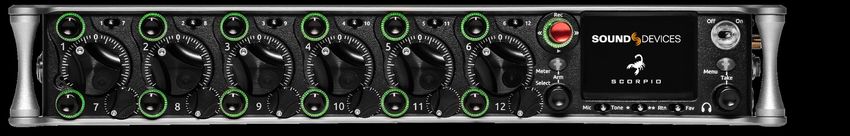
Legal Notices                                                                      Scorpio User Guide | Rev 1-A | 04/04/19
Product specifications and features are subject to change without                  This document is distributed by Sound Devices, LLC in online electronic (PDF)
prior notification.                                                                format only. published in the USA.
                                                                                   This table provides the revision history and cross-reference
Copyright© 2019 Sound Devices, LLC. All rights reserved.                           links to “what’s new” in this guide.
This product is subject to the terms and conditions of a
software license agreement provided with the product, and                           REV #         DATE        VERSION         DESCRIPTION
may be used in accordance with the license agreement.
This document is protected under copyright law. An authorized                       1-A           04/19      A                Preliminary
licensee of this product may reproduce this publication for the
licensee’s own personal use. This document may not be reproduced
or distributed, in whole or in part, for commercial purposes, such
as selling copies or providing educational services or support.
This document is supplied as a technical guide. Special care
has been taken in preparing the information for publication;
however, since product specifications are subject to change,
this document might contain omissions and technical or
typographical inaccuracies. Sound Devices, LLC does not accept
responsibility for any losses due to the user of this guide.

Trademarks
The “wave” logo is a registered trademarks; SuperSlot, and
Wave Agent are trademarks of Sound Devices, LLC. Dante is
a registerd trademark of Audinate. Windows and Microsoft
Excel are registered trademarks of Microsoft Corporation
in the U.S. and other countries. All other trademarks
herein are the property of their respective owners.

Manual Conventions                                                                 Included Accessories
SYMBOL       DESCRIPTION                                                            PART NUMBER           DESCRIPTION

             This symbol is used to show the order in which you select menu         2479.000              Cordset 6’ AC cable
             commands and sub-options, such as: Main Menu > Outputs
     >                                                                              9623.001              XL-WPTA4 power supply TA4 Connector
             indicates you press the Menu button for the Main Menu, then
             scroll to and select Outputs by pushing the Encoder.                   9244.003              Scorpio LCD cover
     []      This symbol is used to convey selectable menu items.                   9772.000              Antenna, SMA connector
     *       This symbol is used to convey factory default settings.                5529.000              Promo Sticker (white)
             A plus sign is used to show button or keystroke combinations. For      5537.000              Promo sticker (black)
             instance, Ctrl+V means to hold the Control key down and press
                                                                                    1312.000              Dot: Red, Yellow, Blue,Green, Purple, White (8 each)
             the V key simultaneously. This also applies to other controls, such
     +       as switches and encoders. For instance, MIC+HP turn means
             to slide and hold the MIC/TONE switch left while turning the
             Headphone (HP) encoder. METERS+SELECT means to hold the
             METERS button down as you press the SELECT encoder.
             A note provides recommendations and important related
     *       information.The text for notes appears italicized.

             A cautionary warning about a specific action that could cause
             harm to you, the device, or cause you to lose data. Follow the
     *       guidelines in this document or on the unit itself when handling
             electrical equipment. The text for cautionary notes also appears
             italicized and bold in a different color.

Post Office Box 576                      +1 608.524.0625 main
E7556 State Rd. 23 and 33                +1 608.524.0655 fax
Reedsburg, Wisconsin 53959 USA              800.505.0625 toll free
www.sounddevices.com                        support@sounddevices.com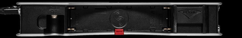
Dear Sound Professionals,
Thank you very much for your interest and purchase of the Scorpio. We at Sound Devices are extremely proud of
this product. We consider the Scorpio our best yet, from every aspect.

We also want to thank you for your direct contribution to this product’s success. Countless conversations were
shared with industry professionals regarding workflows, frustrations, wants, and needs. The knowledge obtained
from these conversations drove the design and engineering of the Scorpio.

Please stay in touch. We will always be here to help, listen to feature requests, and hear about your adventures
with the Scorpio.

We are honored to be part of your kit.

Sincerely,
Sound Devices

Scorpio Preliminary User Guide                                                                                     1
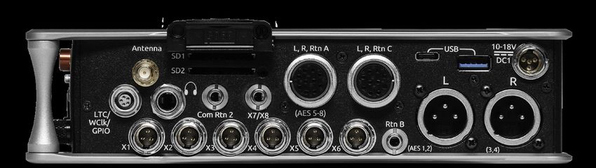
Table of Contents
  PANEL VIEWS			3
  FRONT PANEL			3
  LEFT SIDE PANEL		              4
  RIGHT SIDE PANEL		             5
  REAR SIDE PANEL		              6
  TOP PANEL			6
  HOME SCREEN			7
  CHANNEL SCREEN		               8
  MENUS			10
  POWER MENU			11
  BUS MENU			12
  OUTPUT MENU			13
  DANTE OUTPUT ROUTING		         13
  SLATE/COMS/RETURNS		           17
  FILES MENU			18
  FRONT PANEL SHORTCUTS          22
  SPECIFICATIONS		               24
  GLOSSARY			27

Scorpio Preliminary User Guide        2

Panel Views
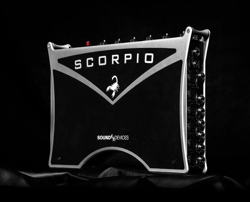
FRONT PANEL
Channel Trim Channel Fader Meter Button LCD Display
Channel Ring LED PFL Switch Transport Control Power Switch/LED Indicator
Menu Button
Headphone
Encoder
Select Encoder Mic/Tone Switch */** Switch Rtn/Fav Switch
CHANNEL TRIM Turns the channel on/off and sets the input METER BUTTON Push to view and select various metering presets.
sensitivity for the channel. To conserve power, turn off unused Used with Select Encoder. Push again to return to Home Screen.
channels by rotating channel trim fully counter-clockwise.
SELECT ENCODER
CHANNEL LED RING Provides visual indication of channel signal 1. Push to view Outputs list, rotate and push to Select Output Screen.
condition, solo and mute, and whether a channel is on or off. Push Meter Button to return to Home Screen.
2. Rotate to select track in display, push both Meter and Select at
CHANNEL FADER Controls the audio level of the channel as it
the same time to arm/disarm track. While holding the Meter Button,
contributes to the L/R mix and any destinations selected in routing as
multiple consecutive tracks may be armed by holding in the Select
“Post”.
Encoder and rotating.
PFL SWITCH Pre/Post Fade Listen selects the channel in the 3. Use with Meter Button to scroll through meter views then push to
headphones for Pre/Post Fade Listen while simultaneously entering Select.
the channel screen. Also used for accessing virtual keyboard for 4. Push with Channel Select switches 1-12 for shortcut to Bus 1-10,
channel naming and various shortcuts. L,R routing.
5. Menu navigation and push to Select.
TRANSPORT CONTROLS A joystick (with its illuminated LED
ring) on the front panel is used to perform various transport control MIC/TONE SWITCH Toggle slate mic and tone generator. Soft
functions. (see table below) button for menus.
*/** SWITCH Shortcut with PFL switch to access channels 13-24
Function Action and 25-32. Soft button for menus.
Record Push up the Transport control to begin recording a new file. POWER SWITCH/LED INDICATOR Turns the power on and off.
The LED ring illuminates red while recording is underway. Switch LED ring indicates the following:
Stop Press in the Transport control to stop recording or playback. 1. Power condition: green = good, orange = warning, red = shutdown
While in standby, press and hold to display next take name. imminent.
2. Flashing blue = power is off and holding timecode .
Play Push down on the Transport control to begin playback of the
last file recorded or file currently loaded. While in playback, 3. Continuous blue = booting up.
push down again to pause playback. The LED ring as well as 4. Flashing yellow = unit is off and charging L-mount batteries.
the active file in the display will flash to indicate that Pause is 5. Continuous yellow = unit is off and both L-mount batteries are fully
active. Push down again to continue playback. charged.
Rewind / Load While in standby, push left to load the previous take. While in MENU BUTTON Push to enter the Main menu. Also used to exit
Previous Take playback, push and hold left to rewind. menus.
When the Scorpio is playing back or paused, moving the HEADPHONE ENCODER
joystick to the left () fast forwards at 2x speed, then after
holding for 5 seconds, it increases to 16x speed.
Scrub While playing or paused, press the headphone encoder to
enter Scrub mode. Then rotate clockwise for fast forward or
counter-clockwise for rewind speeds of 0x, 1/8x, 1/4x, 1/2x,
1x, 2x, 4x, 8x, and 16x. The audio may be heard in scrub
mode up to 2x speed.
Scorpio Preliminary User Guide 3LEFT SIDE PANEL
Mic/Line Inputs 1-6 female XLR jacks Headphone/(X9/X10)
AES3/AES42 on XLR Inputs 1 and 6 3.5mm jack
Mic/Line Inputs 7-8 Mic/Line Inputs 9-16 Com Rtn 1 TA3 jack Headphone/
TA3 jacks TA5 jacks Headset/External Slate
Mic TA5 jack
INPUTS 1-6 FEMALE XLR JACKS Active-balanced analog COM RTN 1 TA3 JACK Balanced connection for Com Return 1 audio
microphone or line-level inputs. Inputs 1 and 6 can also accept AES3 input. [pin-1 = Ground, pin-2 = hot (+), pin-3 = cold (-)].
or AES42 signal. [pin-1 = ground, pin-2 = hot (+), and pin-3 = cold (-)] HEADPHONE/(X9/X10) 3.5 MM JACK Unbalanced output and
MIC/LINE INPUTS 7-8 TA3 JACKS Active-balanced analog TRS headphone output. Warning! This output can drive headphones
microphone or line-level inputs. [pin-1 = ground, pin-2 = hot (+), pin 3 to potentially dangerous levels. Routing determined in the Outputs
= cold (-)]. menu. [Sleeve = ground, tip = left (X9), ring = right (X10)]
MIC/LINE INPUTS 9-16 TA5 JACKS Active-balanced analog HEADPHONE/HEADSET TA5 JACK headphone and slate
microphone or line-level inputs. [pin-1 = ground, pin-2 = Ch.1 +, pin-3 microphone connections [pin-1 = HP right, pin-2 = HP left, pin-3 =
= Ch.1 -, pin-4 = Ch.2 +, pin-5 = Ch. 2 -]. ground, pin-4 = Mic -, pin-5 = Mic+]
Scorpio Preliminary User Guide 4RIGHT SIDE PANEL
Antenna SMA SD Card slots 1 & 2 L,R,Rtn C 10 pin jack USB A port
connector
1/4” headphone jack L,R,Rtn A (AES 5-8) USB C Port 10-18 V DC1 TA4 jack
10 Pin jack
LTC/Wordclock/5-pin X1-X6 Com Rtn 2 X7/X8 Rtn B Main Outputs L (AES 1,2),
LEMO jack TA3 jacks 3.5 mm jack 3.5 mm jack 3.5 mm jack R (AES 3,4) Male XLR jacks
ANTENNA RP-SMA-MALE CONNECTOR Connects to inducted ¼” HEADPHONE JACK 1/4-inch TRS headphone output. Warning!
external antenna for Bluetooth LE. This output can drive headphones to potentially dangerous levels.
[Sleeve = ground, tip = left, ring = right].
SD 1 AND 2 CARD SLOTS Insert SD card media for recording.
Insert label side down. COM RTN 2 3.5 MM JACK Balanced, 1-channel 3.5 mm female
connector for Return 2 audio input. [Sleeve = ground, tip = hot, ring =cold ].
L,R,RTN A (AES 5-8) AND C 10-PIN JACKS Each connection
includes a pair of outputs and a stereo unbalanced return input. X7/X8 3.5MM JACK Unbalanced stereo 3.5 mm female connector.
Analog Output levels are selected between Line, -10, and Mic levels in Routing determined in the Outputs menu. [Sleeve = ground, tip = X7,
Main menu > OUTPUTS section. 10-pin A outputs can be set to send ring = X8].
AES3 digital signals (AES 5-8). Output may be sourced from L,R or any
X1-X6 TA3 JACKS Line, -10, or Mic level selected in Main menu
of the 10 mix busses in Main menu > OUTPUTS.
OUTPUTS section. Routing determined in the Outputs menu. [pin-1 =
USB C PORT Ground, pin-2 = hot (+), pin-3 = cold (-). Float pin-3 to un-balance].
1. File transfer
RTN B 3.5 MM JACK Unbalanced stereo 3.5 mm female connector
USB A PORT for Return B audio input. [Sleeve = ground, tip = left, ring = right].
1. USB keyboard
MAIN OUTPUTS L (AES 1,2), R (AES 3,4) XLR JACKS Analog
2. USB to SD-Remote Android app
outputs on standard 3-pin XLR-3M connectors. Analog Output levels
3. USB to approved 3rd party fader controllers
are selected between Line, -10, and Mic levels in Main menu >
10-18V DC1 TA4 JACK Accepts DC voltages from 10–18 V for OUTPUTS. Can be set to send AES3 digital signals (1,2 and 3,4 on L
powering. [pin-1- GND, pin-2- Smart Battery DATA, pin-3- Smart and R respectively) in Main menu > OUTPUTS. Routing determined in
Battery CLOCK, pin-4- +10-18 VDC]. the Outputs menu. [pin-1 = Ground; pin-2 = hot (+); pin-3 = cold (-).
Unbalance by floating pin-3].
LTC/WORDCLOCK/5-PIN LEMO JACK Timecode I/O, Wordclock.
[pin-1- GND, pin-2- LTC or WORDCLOCK IN, pin-5- LTC or WORDCLOCK
OUT (Pins 2 and 5 are software selectable)].
Scorpio Preliminary User Guide 5REAR SIDE PANEL
10-18 V DC 2 TA4 jack Battery 1, Battery 2 Docking Dante /Ethernet RJ-45 jacks
10-18V DC2 TA4 JACK Accepts DC voltages from 10–18 V for DANTE RJ45 JACKS Two-1 GbE ports serving as a Dante audio
powering. [pin-1- GND, pin-2- Smart Battery DATA, pin-3- Smart network connections. The Dante interface provides 32 inputs and
Battery CLOCK, pin-4- +10-18 VDC]. 32 outputs simultaneously. Routing is defined through the Channel
Source and Output menus. Dante Controller app on Mac/PC (from
BATTERY 1, BATTERY 2 DOCKING Sony L-Mount type batteries
Audinate) needed to route and use Dante.
may be used. When connected to an external DC source via DC1 or
DC2 the L-Mount batteries can be charged if enabled in the Power
menu.
TOP PANEL
Expansion connector for SL-6
Test connector for manufacturing
EXPANSION CONNECTOR FOR SL-6 Connection for Sound TEST CONNECTOR Used during manufacturing.
Devices SL-6 modular wireless receiver system. Routing is defined
through the Channel Source menu.
Scorpio Preliminary User Guide 6Screen Views
HOME SCREEN
Current take name Media space
remaining indicators
Individual channel
meters
LR mix bus meters
File elapsed time Selected
headphone preset
Timecode Current sample rate
Current frame rate Metering for
Returns A, B, C
CURRENT TAKE NAME Shows the filename of the currently- TIMECODE Indicates current SMPTE timecode value.
selected take.
CURRENT SAMPLE RATE, FADER/TRIM LEVEL
SSD, SD1, SD2 Indicates the used/remaining space of each form of 1. Indicates current sample rate.
media. The internal SSD drive has a capacity of 256 GB. 2. Temporarily indicates fader level of last moved fader (red text box).
3. Temporarily indicates trim level of last moved trim (green text box).
LR MIX BUS METERS WITH ARM/DISARM INDICATION
Indicates the peak and VU audio levels of the L/R mix. The L and R CURRENT TIMECODE FRAME RATE, FADER/TRIM LEVEL
indicators turn red to indicate that the tracks are armed for record. 1. Indicates current frame rate.
2. Temporarily indicates fader level of last moved fader (red text box).
INDIVIDUAL CHANNEL METERS WITH ARM/DISARM INDICATION
3. Temporarily indicates trim level of last moved trim (green text box).
Indicates the peak and VU audio levels of the individual channel. May
be Pre- or Post- fade depending on Channel to Iso routing. SELECTED HEADPHONE PRESET Indicates the currently-selected
headphone preset.
FILE ELAPSED/ REMAINING TIME Indicates in
Hours:Minutes:Seconds:1/10ths the elapsed time of the current file. METERING FOR RETURNS A, B AND C Indicates audio level for
During playback, displays the elapsed and remaining time in hours, the returns.
minutes and seconds.
Scorpio Preliminary User Guide 7CHANNEL SCREEN
Channel desgination
and user-defined name
Channel Meter view
Channel Trim value Channel Fader Value
Channel Input selection Channel to ISO routing
Channel Linking Channel EQ
HPF (High Pass Filter) Polarity
Channel delay Bus 1 send
Limiter Bus 2 send
Slate Mic
Channel Mute L C R pan select Bus Routing
CHANNEL DESIGNATION AND USER-DEFINED NAME Indicates CHANNEL EQ Indicates the EQ position in the audio chain. Pre(fade)
the mixer channel designation and the user-defined name. Both are or Post(fade). Select to enter Channel EQ screen.
overlaid onto the channel audio meter. When in a Channel Screen,
HPF (HIGH PASS FILTER)
hold the PFL Switch for about 0.5 s to enter the virtual keyboard and
Indicates on/off status where green icon and white value = ”On” and
enter a user-defined name for the channel.
grey icon and value = “Off”. The HPF frequency is variable in 10 Hz
CHANNEL METER VIEW Indicates the audio level of the channel. steps from 10 Hz to 320 Hz.
Metering follows ISO Routing selection, Pre- or Post-fade.
POLARITY REVERSE Indicates polarity status. Green icon = polarity
CHANNEL TRIM VALUE Indicates the gain of the channel trim con- reversed, white icon = polarity normal.
trol. The gain range depends on the type of input selected.
CHANNEL INPUT DELAY Indicates input delay time. The input delay
Mic: +12 to +76 dB
is continuously-variable in milliseconds from 0-50 ms.
Line: -14 to +36 dB
SL-6: -20 to +50 dB BUS 1 SEND Sends channel’s audio to Bus 1. The level is continu-
Dante: -10 to +20 dB ously-variable from Off to +16 dB.
AES3: -10 to +20 dB
CHANNEL LIMITER Indicates on/off status of channel limiter.
AES42: 0 to +70 dB
Returns: -20 to +30 dB BUS 2 SEND Sends channel’s audio to Bus 2. The level is continu-
ously-variable from Off to +16 dB.
CHANNEL FADER VALUE Indicates the level of the channel fader
control, continuously-variable from Off to +16dB. MUTE Indicates mute status of channel. Blue icon = muted. Toggle
mute on/off with the “Tone” switch.
CHANNEL INPUT SELECTION Indicates which physical audio input
is feeding the channel. L C R SELECT Indicates the stereo pan position of the channel’s
contribution to the L/R mix. Orange = selected. Use the */** switch
ISO (CHANNEL->ISO) ROUTING Indicates where the isolated
to select. Hold */** switch and rotate select encoder for continuous
track’s audio is tapped from in the audio chain. Pre-fade or Post-fade.
panning positioning. Alternatively, press and hold Select encoder,
CHANNEL LINKING Indicates the current linking status. The linking then use */** switch to pan continuously.
options are Unlinked, adjacent channels (eg. 1,2) and adjacent chan-
BUS ROUTING Indicates channel to bus routing. Green = pre-fade,
nels Mid Side (eg. 1-2MS). Linked parameters are: trims, faders, HPF,
Orange = post-fade, Light Blue = via Bus Send, White = No route. Use
delay, limiter, mute, ISO, Bus Send 1 and Bus Send 2. Stereo panning
the Rtn/Fav switch to access the selected channel’s bus sends view.
is 1 to L and 2 to R. For MS linking, the pan becomes a balance con-
Use the HP encoder to scroll and select the bus type (Pre, Post or
trol between M and S.
Send) and set the gain for the channel’s contribution to the bus. Use
the Menu button to return to the channel screen.
Scorpio Preliminary User Guide 8Virtual Keyboard
Action Function
Rotate HP Scrolls orange highlight through the keyboard
characters.
Press HP Inserts the highlighted character in text field.
‘abc’ switch Quick flick toggles between A-Z and a-z in keyboard.
Hold ‘abc’ Momentary selection of other case.
switch
Delete Deletes character to the left of flashing cursor.
Hold Delete Repeatedly deletes characters to the left of flashing
cursor.
Space Inserts space at the flashing cursor position.
Hold Space Repeatedly inserts spaces.
Save switch Saves text and exits screen.
Rotate Moves the cursor to the left or right in the text field.
Select
Quick Press Switches to the the Shifted functions: Clear, End,
Select Home, Exit. When shifted functions are active, their
text changes to white and the non-shifted functions
change to gray.
Clear Clears text from the text edit field.
End/Home Moves cursor to end/start of text.
Exit Exits screen without saving text edits.
1. EQ Selects channel EQ state. [Off*, On].
2. LOW FREQ Selects low frequency EQ filter parameters.
a. Type- Indicates Shelf or Peaking filter [Shelf, Peak].
b. Freq- Indicates frequency of the filter, continuously-variable from
20 Hz to 20 kHz (100Hz*).
c. Gain- Indicates gain of the filter, continuously-variable from -15dB
to +15 dB in 1 dB increments (0 dB*).
d. Q- Indicates “Q” or bandwidth of the filter, continuously-variable
from .5 - 10 in .1 increments (1.0*).
e. Bypass- Indicates state of the filter [Bypass (orange fill)]*.
3. MID FREQ Selects mid frequency EQ filter parameters.
a. Freq- Indicates frequency of the filter, continuously-variable from
200-20 kHz in 10 Hz increments (5000Hz*).
b. Gain- Indicates gain of the filter, continuously-variable from -15 dB
to +15dB in 1dB increments (0dB*).
c. Q- Indicates “Q” or bandwidth of the filter, continuously-variable
from .5-10 in .1 increments (1.0*).
d. Bypass- Indicates state of the filter [Bypass(orange fill)]*.
4. HI FREQ Selects high frequency EQ filter parameters.
a. Type- Indicates Shelf or Peaking filter [Peak, Shelf].
b. Freq- Indicates frequency of the filter, continuously-variable from 20
Hz to 20kHz. (100 Hz*).
c. Gain- Indicates gain of the filter, continuously-variable from -15dB
to +15dB in 1dB increments. (0 dB*)
d. Q- Indicates “Q” or bandwidth of the filter, continuously-variable
from .5 - 10 in .1 increments. (1.0*)
e. Bypass- Indicates state of the filter. [Bypass (orange fill)]*
5. PRE/POST-FADER Indicates where the EQ is inserted into the
audio chain. Pre-fade or Post-fade [Pre*, Post] *Note: EQ will apply to
bus sends when applied Pre-fade only.
Scorpio Preliminary User Guide 9Menus MAIN MENU Scorpio Preliminary User Guide 10
Power
Allows configuration of various power settings.

POWER SOURCE ICONS “Batt1, Batt2, DC1, DC2, TC Batt, SL-6
DC, SL-6 NP1” Indicates the power condition of each of the power
sources. Green = normal, Yellow = below normal, Orange = low, Red
= warning
1. DC1 REF Allows proper power level indicator calibration based
upon the type of DC power source used. [12V DC*, 14 V Li-Ion, 12
V Lead Acid, NiMH, Expanded NiMH, Full Range (10-18V), Smart
Battery].
2. DC2 REF Allows proper power level indicator calibration based
upon the type of DC power source used. [12V DC*, 14 V Li-Ion, 12
V Lead Acid, NiMH, Expanded NiMH, Full Range (10-18 V), Smart
Battery].
3. DC LOSS Selects how the unit should operate when DC power is
lost. [Switch to Next Supply*, Turn Off].
4. BATT CHARGING Enable/Disable battery charging when connect-
ed to an external DC source. [Enable, Disable*].
5. SL-6 PRIMARY SOURCE Selects the primary power source for
the SL-6. [NP1*, DC Input].
6. SL-6 NP1 REF Allows proper power level indicator calibration
based upon the type of battery used. [14 V Li-Ion*, NiMH].
7. SL-6 DC REF Allows proper power level indicator calibration
based upon the type of DC power source used. [12 V DC*, 14 V Li-Ion,
12 V Lead Acid, NiMH, Expanded NiMH, Full Range (10-18 V)].
8. SL-6 POWER OUTPUTS Enables or disables onboard power
outputs [Off*, On].

*Note: All SL-6 related items are only shown in the display when an
SL-6 is connected to the Scorpio.

Channel Setup
1. PHANTOM VOLTAGE Selects phantom power voltage for all
inputs. [12 V, 48 V*].
2. PFL MODE Selects the source of the PFL feed. [Auto* Pre-fade,
Post-fade] Auto = pre-fade if channel is routed to ISO track pre-fade,
post-fade if channel is routed to the ISO track post-fade.
3. CHANNEL GROUPING Selects grouping of faders, record arming,
and mutes across channels. The lowest channel number in the group
controls the other channels grouped. Four channel groups are possi-
ble, channels grouped can only be assigned to one group.
a. Group 1 [1-16]
b. Group 2 [1-16]
c. Group 3 [1-16]
d. Group 4 [1-16]

CHANNELS 13-32 Selects channel screen for channels 13-32
[Channel 13-32].

Scorpio Preliminary User Guide                                           11
Buses
Selects routing for Buses L,R and 1-10.
1. BUS METER Audio level meter for the selected bus.
2. LINK *-* Selects linking for two even-to-odd numbered adjacent
buses. Links bus Gain, Mute Coms, and Mute All functions.
3. ISO Any ISO channel contributes to Bus mix. Green fill in text box = Bus Meter Link
Pre-fade, Orange fill in text box = Post-fade, Blue fill in text box = Send
(eg. Bus routing screen with Channel 1 box with blue fill = Channel 1
sending to Bus 1 via Aux 1 send) [1-32]. Iso
4. BUS [L,R, 1,2 (available on buses 3-10).
5. RTN COM [Send 1, Send 2, RTN 1, RTN 2 (not available on L,R
busses)].
6. RETURN [A1, A2, B1, B2, C1, C2 (not available on L,R buses)].
7. GAIN Use ** toggle to select and adjust selected bus gain in 1 dB
increments. [Off-16dB].
8. MUTE COMS Selects muting of Coms 1, 2 sends and returns. Mute All
9. MUTE ALL Indicates mute status of bus. Blue icon = muted. Tog-
Bus Output routing Gain
gle Mute All On/Off with the “Fav” toggle.
Bus Meter Link
Iso
Bus
Com
Return
Mute All
Bus output routing Gain Mute
Coms
Scorpio Preliminary User Guide 12Outputs
1. LR, X1-X10 Output Routing
Selects routing for L,R and X1-X10 outputs [L Out, R Out, X1, X2, X3,
X4, X5, X6, X7, X8, X9 and X10 Out] *Only a single source can be rout- Link
ed to an Output. If multiple sources need to be routed, use a Bus*
A. ISO Selected source will contribute to the Output. Green = Pre-
fade, Orange = Post-fade [1-32].
B. BUS [L,R, 1-10, HP-L, HP-R]. A1
C. COM [Send 1, Send 2, RTN 1, RTN 2].
D. RETURN COM [A1, A2, B1, B2, C1, C2].
A2
E. AUTO-MUTE Selects automatic muting of the output when in Stop
mode. Record and Playback modes are not muted.
Auto-Mute
F. DELAY The output delay is continuously-variable in milliseconds
from 0-500 ms. Mute
G. GAIN Selects amount of attenuation applied to the output. Toggle
Delay Attn Type
the ** to select [0 dB to -50 dB and -inf].
H. LEVEL Selects output level type. [Line, -10, Mic].
J. MUTE Indicates mute status of output. Orange = muted. Toggle
Mute On/Off with the “Fav” toggle.
2. 10-Pin A Out Routing
Selects routing for 10-Pin A outputs.
A. A1 Selects mix bus for A1 output [L,R, 1-10].
B. A2 Selects mix bus for A2 output [L,R, 1-10].
C. AUTO-MUTE Selects automatic muting of the output when in Stop
mode. Record and Playback modes are not muted.
D. DELAY The output delay is continuously-variable in milliseconds
from 0-500 ms.
E. GAIN Selects amount of attenuation applied to the output. Toggle
the ** to select [0 dB to -50 dB and -inf].
F. LEVEL Selects output level type. AES option is available for L, R,
10-pin A [Line, -10, Mic].
G. MUTE Indicates mute status of bus. Blue icon = muted. Toggle
Mute On/Off with the “Fav” toggle.
3. 10-Pin C Level
Selects the output level type [Line*, -10, Mic].
4. Dante
Selects routing for Dante outputs.
A. ISO Any source selected will be routed to the selected Dante out-
put. Green fill in text box = Pre-fade, Orange fill in text box = Post-fade
[1-32]
B. BUS [L,R, 1-10].
C. OUTPUT All sources are selected post-delay [L,R, X1-X10].
Scorpio Preliminary User Guide 135. HP Presets
Selects the list of headphone presets available and allows for editing
and creation.
Function Description
Name Displays virtual keyboard and allows for naming of the
headphone preset.
Edit Allows selection of routed sources to both HP Left and HP
Right. Select HP LEFT or RIGHT and then select desired
source.
i. Iso- Any source selected will be routed to the selected
HP output. Green = Pre-fade,
Orange = Post-fade. [1-32]
ii. Bus- [L,R, 1-10]
iii. Return Com- [Send 1, Send 2, RTN 1, RTN 2]
iv. Return- [A1, A2, B1, B2, C1, C2]
Mono Selects monophonic monitoring of selected HP-L/HP-R
sources.
MS Selects monophonic monitoring of selected HP-L/HP-R
sources.
Unlist Deselects a preset in the list preventing it from being
listed in the HP Preset menu (Press HP encoder in Home
Screen).
List Selects a preset in the list allowing it to be listed in the HP
Preset menu (Press HP encoder in Home Screen).
Fav Selects a favorite preset. The name turns green when
selected. The “Fav” switch recalls this HP preset when in
the Home Screen.
Limiters
CHANNEL LIMITERS QUICK SETUP Selects the channel limiters
on/off status globally. [All On*, All Off]
BUS LIMITERS Selects the bus limiters on/off status globally. [All
On*, All Off]
HEADPHONE LIMITERS Selects the headphone limiters on/off
status. [On, Off*]
KNEE TYPE Selects the knee type of the limiter. [Hard*, Soft]
RATIO Selects the ratio of the limiter. [Inf:1*, 20:1]
RELEASE TIME Selects the release time of the limiters in 10 ms
increments. 200 ms* [50-1000 ms]
CHANNEL THRESHOLD Selects the threshold at which the channel
limiters activate. -4 dBFS Default [-2 to -12 dBFS]
BUS THRESHOLD Selects the threshold at which the bus limiters
activate. -4 dBFS Default [-2 to -16 dBFS]
LR LINKING Selects the linking of the L and R limiters. [On*, Off]
BUS 1,2 LINKING- Selects the linking of the bus 1 and 2 limiters.
[On, Off*]
BUS 3,4 LINKING Selects the linking of the bus 3 and 4 limiters.
[On, Off*]
BUS 5,6 LINKING Selects the linking of the bus 5 and 6 limiters.
[On, Off*]
BUS 7,8 LINKING Selects the linking of the bus 7 and 8 limiters.
[On, Off*]
BUS 9,10 LINKING Selects the linking of the bus 9 and 10 limiters.
[On, Off*]
Scorpio Preliminary User Guide 14Meters Selected Preset METER PRESETS 1-12 A. PEAK HOLD TIME Selects the peak hold time for the meter preset. [Off, 1*-5s., Infinity] B. METER RANGE Selects the range of the meters from bottom to top of scale. [50 dB*, 40 dB, 20 dB] C. METER VIEW Selects the meters to be viewed in the current preset. [LR,1-8, LR,9-16, LR,17-24, LR,25-32, LR,1-16, LR,17-32, LR,1-12, LR,13-24, LR,1-32, LR,Outputs, LR,Buses, LR,Returns] D. TRACK NAMES Selects display of track name in meters. [Enabled*, Disabled] E. GRAY METERS Selects gray meter when record disarmed. [When disarmed*,Off] Timecode TIMECODE MODE Selects the timecode mode of operation. [Off, Record Run, Free Run*, Free Run Auto Mute, Free Run Jam Once, 24 Hour Run (ToD), 24 Hour Run Auto Mute, Ext TC, Ext TC - Auto Record, Ext TC Continuous, Ext TC Cont. - Auto Record] FRAME RATE Selects the current frame rate. [23.98, 24, 25, 29.97 ND, 29.97 DF, 30 ND*, 30 DF] HOLD OFF Selects the amount of time incoming Timecode needs to be valid prior to entering record when in auto-record mode. [0.0*-8.0 seconds in steps of 0.1 sec.] JAM Indicates the Received TC, Generator TC and the calculated difference between the two. Received and Generator UBits are shown. Jamming to external TC and UBits is supported. a. Jam TC- Toggle Rtn/Fav switch to jam to external TC. SET GENERATOR TC Provides the ability to start rolling internal TC from a manually entered value in the format of HH:MM:SS:ff SET GENERATOR UBITS Provides UBits manual and automatic entry. [U=User entered UU:UU:UU:UU*, mm:dd:yy:UU, dd:mm:yy:UU, Use External] Use Rtn/Fav toggle to exit. LEMO OPTIONS Selects pin-2 and pin-5 options for TC Lemo connector. a. Pin-2 - [TC In*, WCK In, WCK Out] b. Pin-5 - [TC Out, WCK Out] SYNC REFERENCE Selects current sync reference. [Internal*, Word Clock, LTC In] Scorpio Preliminary User Guide 15
Record/Play
SAMPLE RATE Selects the current sample rate. [44100, 47952,
48000*, 48048, 96000, 192000]
BIT DEPTH Selects the current bit depth. [16, 24*]
PRE-ROLL TIME Selects the amount of Pre-roll recording. Adjustable
in 1 second increments. *2 s. [0-5 s.]
POST-ROLL TIME Selects the amount of Post-roll recording. Ad-
justable in 1 second increments. [0-10 s.] If a recording is stopped
prematurely, press record within the post-roll time. The machine will
continue to record into the original file. Useful for when directors call
‘cut’ prematurely. During the post roll period, the transport joystick
ring LED shows orange. Pressing stop again during the post-roll period
cancels the post roll and stops recording.
TRACK TO MEDIA MENU Selects the sources for each recording
media as well as the .wav file type recorded. Tracks may be routed
to media to be recorded as Mono or Poly files. (Green fill in text box=
Mono file, Blue fill in text box= Poly file)
a. SSD- [ISO, L/R, Bus1/2, ALL]
b. SD1- [ISO, L/R, Bus1/2, ALL]
c. SD2- [ISO, L/R, Bus1/2, ALL]

* Note: Up to 36 track recording supported with sampling rates 44.1-
96 kHz. Up to 18 track recording at 192 kHz.
**Note: Monophonic file recording up to 48.048 kHz.
DEFAULT PLAYBACK DRIVE Selects the drive for playback. [SSD,
SD1, SD2]

Scorpio Preliminary User Guide                                              16
Slate/Coms/Returns
SLATE/COM MIC SOURCE Selects the slate and com mic source.
[Off, Int Mic*, Ext Mic, Ext 12 V Mic]
SLATE/COM MIC GAIN Selects the gain for the slate/com mic. [0-
20 dB in 1 dB steps for the internal mic, 0-60 dB in 1 dB steps for the
external mic].
SLATE ROUTING Selects the destination(s) for the slate mic.
a. Track- [1-32]
b. Output- [L,R, X1-X10]
c. Bus- [L,R, 1-10] [Mute Program, Unmute Program, Duck Program]
d. HP- [HP-L, HP-R] [Mute Program, Unmute Program, Duck Program]
e. Duck By: [0- -40 dB]
COM SEND 1 ROUTING Selects the destination(s) for Com Send 1.
a. Output- [L,R, X1-X10, A1,A2]
b. Bus- [L,R, X1-X10, Mute Program]
c. HP- [HP-L, HP-R, Mute Program]
d. Duck By: [0- -40 dB]
COM SEND 2 ROUTING Selects the destination(s) for Com Send 2.
a. Output- [L,R, X1-X10, A1,A2]
b. Bus- [L,R, X1-X10, Mute Program]
c. HP- [HP-L, HP-R, Mute Program]
d. Duck By: [0- -40 dB]
COM RTN1 GAIN Selects the gain for COM RTN 1 in 1 dB
increments. [0-30 dB]
COM RTN2 GAIN Selects the gain for COM RTN 2 in 1 dB
increments. [0-30 dB]
RTN A GAIN Selects the gain for RTN A in 1 dB increments. [0-30
dB]
RTN B GAIN Selects the gain for RTN B in 1 dB increments. [0-30
dB]
RTN C GAIN Selects the gain for RTN C in 1 dB increments. [0-30
dB]

Scorpio Preliminary User Guide                                            17
Files
 USB FILE TRANSFER Enters USB file transfer mode. Files may be
 transferred between a Mac or PC and Scorpio via USB-C port.
 *Note: when in USB file transfer mode, all other audio playback and
 record functions are suspended.
 TAKE LIST Enters the Take List. The Take List shows a running list of
 recorded takes in chronological order, most recent at the top. Various
 details of each take are indicated on the right side of the display: TC
 (timecode), Duration, Media, Folder, Scene, Take, Date, and Notes.
 From this list, takes may be selected for metadata editing by using the
 Rtn/Fav toggle.
 FILE LIST Enters the File List. The File List displays the Scorpio’s
 internal SSD and SD cards and their contents. Various details of
 each drive, folder, and WAV file are indicated on the right side of the
 display: TC, FPS:, duration, format, tracks, date, time, size.
 SOUND REPORT INFO Selects the various content for each field of
 a sound report.
 SCENE INCREMENT MODE Defines whether a scene name shall be
 incremented numerically or alphabetically when the scene increment
 shortcut is used.
 TAKE RESET MODE Selects when a take number shall reset to 1
 when the scene or daily folder changes.
 ERASE/FORMAT SSD Select to erase/format the internal SSD.
 ERASE/FORMAT SD1 Select to erase/format SD1.
 ERASE/FORMAT SD2 Select to erase/format SD2.

Scorpio Preliminary User Guide                                             18
SL-6
*Note: The SL-6 menu is only available when an SL-6 is connected.
Power must be connected to the SL-6 via the SL-6 power connections
for use with Scorpio.
RECEIVER OVERVIEW Information including RF level, Transmitter
battery level, channel frequency, and audio level.
RECEIVER SLOT POWER Selects powering on and off of each SL-6
receiver slot.
ANTENNA A POWER (BIAS) Selects 12 VDC power for active anten-
na use.
ANTENNA B POWER (BIAS) Selects 12 VDC power for active anten-
na use.
ANTENNA FILTER Selects the SL-6 front-end filter bandwidth.
a. Wideband.
b. 470-700MHZ.
c. 470-590MHZ.
d. 580-700MhZ.

Scorpio Preliminary User Guide                                       19
System

TONE SETUP Selects the level, frequency, and routing of the
internal tone generator.
a. Level- Selects the level of the tone generator from -20 - 0 dBFS in 1
dB increments. [-20 - 0 dBFS]
b. Frequency- Selects the frequency of the tone from 100 to 10 kHz in
10 Hz steps. [100-10 kHz]
c. Track- [1-32]
d. Output- [L,R, X1-X10]
e. Bus- [L,R, 1-10] [L-ident]
NOTIFICATION BELLS Selects settings for the notification bells.
a. To HP- Routes notification bell tones to the headphones. [HP-L,
HP-R]
b. To Bus- Routes notification bell tones to the buses. [L,R, 1-10]
c. When…- Selects when the notification bell tones are used. [Rec/
Stop, Space Low, Power Low, Warning Popup]
d. Level- Selects the level at which the notification bell tones will be
played in 1 dB increments. [Muted, -60 to -12dBFS]
FADER CALIBRATION Selects the option to manually
calibrate all faders.
BRIGHTNESS Selects the brightness of the LED display and
front panel LEDs.
a. LED Brightness- Selects the front panel LED brightness in 10%
steps. [10%-100%]
b. Selects the front panel LCD display brightness in 10% steps. [10%-
100%]
TIME/DATE Selects the current date and time.
a. Time Format- [12*, 24 hr]
b. Date Format- [mm/dd/yy*, dd/mm/yy, yy/mm/dd]
c. Set Time/Date- Selects the current date and time
d. Time Zone- [-12 to +13 hours GMT]
e. Daylight Saving- [On, Off*]
VERSION INFO Indicates current firmware version
FIRMWARE UPDATE Selects any *.prg update files present on any
media.

Scorpio Preliminary User Guide                                             20
Quick Setup
LOAD GLOBAL SETTINGS Selects a saved settings file for loading.
[User-saved Global settings]
SAVE GLOBAL SETTINGS Saves Global settings to various
destinations. [SSD Drive (internal), INT1-4 (internal), SD1 and SD2]
LOAD FACTORY SETTINGS Selects factory settings to be loaded for
entire unit.

Scorpio Preliminary User Guide                                         21
Front Panel Shortcuts
 quick = quickly flick toggle for < 0.5 seconds
 Channel Screen access and PFLs
 Hold PFL (1-12)                                                          PFL channel (1-12) and stay on current screen
 PFL (1-12) quick                                                         PFL channel (1-12) and access channel screen
 Hold * then PFL (1-12)                                                   PFL channel (13-24) and stay on current screen
 Hold * then PFL (1-12) quick                                             PFL channel (13-24) and access channel screen
 Hold ** then PFL (1-8)                                                   PFL(25-32) and stay on current screen
 Hold ** then PFL (1-8) quick                                             PFL channel (25-32) and access channel screen

 Meter View, Menu, Output, and HP Preset Quick Access
 Hold Meter then PFL (1-12)                                               Accesses METER views 1-12 respectivly
 Hold Select then PFL (1-12)                                              Accesses BUS screens L,R, X1-X10 respectivly
 Hold HP then PFL (1-12)                                                  Acesses HP presets 1-12 respectively
 Press Meter                                                              Displays meter view popup list. Then scroll using Select
                                                                          or PFL 1-12 to select favorite menu 1-12
 Press Select                                                             Displays outputs popup list. Then scroll using select
                                                                          to select output screen L,R,X1-X10
 Press HP                                                                 Displays HP preset popup list. The scroll using HP to select HP preset 1-12

 In Channel Screen
 Rotate then press Select                                                 Navigate to, then enter a channel screen field
 */**                                                                     3-position pan adjustment LCR
 Hold Select then */**                                                    Continuous pan adjustment (L10 to R10)
 Hold */** then rotate Select                                             Continuous pan adjustment (L10 to R10)
 Hold PFL > 0.5 seconds                                                   Shortcut to channel naming

 Other Button Shortcuts
 Meter + Select or Select + Meter                                         Arm or disarm Slected track
 Menu + HP or HP + Menu                                                   Accesses Take List
 HP + Play                                                                Switches the playback drive between SSD, SD1, SD2
 Hold Meter then Select                                                   Arms or disarms multiple individual tracks at one time
 Hold Meter then press and rotate Select, then release Select and Meter   Arms or disarms multiple consecutive tracks at one time

Scorpio Preliminary User Guide                                                                                                                          22
Scorpio is capable of connecting to a Dante network, receiving and
sending up to 32 channels of audio simultaneously at sample rates
from 44.1 kHz up to 96 kHz and 16 channels at 192 kHz. Scorpio
channels 1-16 may be sourced from Dante receive channels 1-16.
Scorpio channels 17-32 may be sourced from Dante receive channels
17-32. Each Dante input may be selected as a source in the channel
setup menu. Each Dante output may be sourced from Isos (pre- or
post-fader), Buses, and Outputs (post-delay). All network routing
should be done through Audinate’s Dante Controller application,
found at www.audinate.com. Once the initial configuration has been
performed, the Scorpio will keep its Dante configuration through
power cycles. It is recommended that in most situations Scorpio is
selected as “Preferred Master” under the “Clock Status” tab of Dante
Controller.
USB-A
USB-A allows multiple devices to be used to control and monitor vari- USB KEYBOARD
ous functions of Scorpio. Should multiple devices be used simultane- A USB keyboard connects to Scorpio via the USB-A port. The keyboard
ously, the use of a USB-A type hub is required. is used for metadata entry as well as the following shortcuts:
Key Scorpio Function
EXTERNAL CONTROLLERS
ESC “Back” or Cancel Virtual Function
Scorpio supports select 3rd-party USB controllers via open MCU
protocol. F1 or Menu Menu
Control and display parameters include the following: F2 Take List
1. Channel Name
F3 Toggles through all meter views
2. Channel Faders
3. Channel Trims Ctrl + R Record
4 Channel Pans Ctrl + S Stop
5. Channel Mutes
6. Channel Solos Spacebar Play/Pause
7. Channel Record Arm/Disarm Up/Down Arrows Up/down navigation
8. Channel “fat channel” (Source, Limiter, HPF, EQ, Bus sends)
9. Channel bank switching Enter Selects highlighted items in menus
10. Bus Master Faders In meter views, opens the HP Preset list
11. Output Master Faders Alt + Enter Track Arm/Disarm of selected tracks
12. Transport Controls
SD-REMOTE
SD-Remote is an Android tablet application, available in the Google USB-C
Play Store. It is designed to pair with Scorpio and display parameters USB-C allows for high-speed file transfer between a computer and any
including the following: of the Scorpio’s media.
1. Channel Meters *All other functionality is suspended in USB File Transfer mode.
2. L/R Meters
3. Channel Name
4. Channel Solos
5. Channel Record Arm/Disarm
6. Transport Controls
7. Metadata Editing
8. Various Status Info
9. Timecode
10. Channel Mutes
SETUP PROCEDURE
1. Download and install SD-Remote from the Google Play Store
2. Connect Android tablet to Scorpio via USB-A port
3. On the Android tablet, open the quick settings drop down menu
4. Touch “USB Android System” twice to open “Use USB to” dialog box
5. Touch “Connect a MIDI device”
6. Open SD-Remote app
Scorpio Preliminary User Guide 23Specifications
Specifications are subject to change without prior notice.
For the latest information available on all Sound Devices products,
visit our website: www.sounddevices.com.
FREQUENCY RESPONE MAXIMUM GAIN
10 Hz to 80 kHz ± 0.5 dB (192 kHz sample rate, re 1 kHz) Trim stage (mic input): 76 dB
Trim stage (line input): 36 dB
THD + NOISE Fader stage: 16 dB
0.005% max (mic in, 1 kHz, 22 Hz–22 kHz BW, trim at 20, fader at 0,
-10 dBu in) Bus stage: 16 dB
Headphone stage: 20 dB
EQUIVALENT INPUT NOISE Mic-to-Line: 108 dB
-131 dBV (-129 dBu) max (mic in, A-weighting, 76 dB gain, 150 ohm Mic-to-Headphone: 112 dB
source impedance) TA5 (along with mic input pins) for single connection to headset + mic
PROCESSING ENGINE High output, 4 ohm output impedance, 400 mW + 400 mW at each
Highly extensible, full FPGA-based audio processing, 3 FPGAs connector, all individually driven
Six-way ARM multiprocessor system Compatible with headphones of any impedance
64-bit audio processing precision OUTPUTS
AUDIO OVER ETHERNET XLR (L, R) active-balanced, 250/3.2k/120 ohms (mic/-10/line)
Dante, AES67 compatible Hirose 10-pin (L, R) active-balanced, 250/3.2k/120 ohms (mic/-10/
32 channels in, 32 channels out (up to 96 kHz); 16 channels in, 16 line)
channels out (192 kHz) TA3 (X1-X6) active-balanced, 250/3.2k/120 ohms (mic/-10/line)
1 Gb/s Ethernet, 2 ports, transformer-balanced 3.5mm (X7, X8): unbalanced, stereo, 1.8k ohms
INPUTS HEADPHONE OUTPUTS
Mic/Line inputs: 16 total, all fully featured; 6 on full-size XLR, 2 on ¼”, 3.5 mm
TA3, 8 on TA5 TA5 (along with mic input pins) for single connection to headset + mic
Mic-level inputs: (XLR, TA3, TA5): Class-A, discrete differential long-tail High output, 4 ohm output impedance, 400 mW + 400 mW at each
pair, 4k ohm input impedance connector, all individually driven
Line-level inputs: (XLR, TA3, TA5): active-balanced, 4k ohm input Compatible with headphones of any impedance
impedance MAXIMUM OUTPUT LEVEL
48V phantom: full 10mA to all 16 inputs simultaneously (all into 10k load)
AES3 or AES42 available on XLR inputs 1 and 6 Line: +20 dBu (7.8 Vrms)
AES42: +10 V, 250 mA available, mode-1, auto-ASRC “-10”: +6 dBu (1.5 Vrms)
Rtn A, B, C (3.5 mm/10-pin): unbalanced 2-channel, 4k ohm input Mic: -20 dBu (0.078 Vrms)
impedance X7/X8 Out: +6 dBu (1.5 Vrms)
Com Rtn 1,2 (TA3, 3.5mm) balanced, 1-channel, 8k ohm input Headphone outputs (¼”, TA-5, X9/X10): +14 dBu (4.0 Vrms)
impedance
External Slate Mic (TA5): balanced, 8k ohm input impedance, menu- A/D CONVERTERS
selectable 12 V phantom 32-bit, 120 dB, A-weighted dynamic range typical
Sampling rates 44.1 kHz, 47.952 kHz, 48 kHz, 48.048 kHz, 88.2 kHz,
MAXIMUM INPUT LEVEL 96 kHz, 192 kHz
Mic: +8 dBu (2.0 Vrms)
Line: +28 dBu (19.5 Vrms) DIGITAL OUTPUTS
Rtn A, B, C: +18 dBu (6.2 Vrms) AES3 transformer-balanced, in pairs; 1-2 (XLR-L), 3-4 (XLR-R), 5-8
Com Rtn 1, 2: +24 dBu (12.3 Vrms) (Hirose 10-pin A)
External Slate Mic: +12 dBu (3.2 Vrms) 110 ohm, 2 V p-p, AES and S/PDIF compatible
HIGH-PASS FILTERS RECORDING
Adjustable 40 Hz to 320 Hz, 18 dB/oct. 1st stage analog (before Internal 256 GB SSD; two removable SD Cards. 10% over-provisioned
preamp), 2nd stage digital. for optimum performance
Simultaneous recording to internal SSD and the two SD cards
LIMITERS
exFAT formatting
Limiters available at all channels, buses, headphones, for all sample
36 tracks (32 iso channels, 4 buses)
rates
Broadcast WAV monophonic and polyphonic file format
Analog first stage, all subsequent stages digital
64-bit WAV (RF64) monophonic and polyphonic; support for files > 4 G
Attack time: 1 ms
Release time: adjustable, 50 ms to 1000 ms USB
Threshold: adjustable, -2 dBFS to -12 dBFS USB-C (USB 3.1 type 1) for file transfer of internal SSD, both SD Cards.
Selectable knee: hard or soft USB-A host for keyboard, external controller, external USB hubs
Selectable ratio: inf:1, 20:1 supported for connecting multiple devices.
DELAY
Channel Adjustable 0-50 ms
Output Adjustable 0-500 ms
Scorpio Preliminary User Guide 24TIMECODE AND SYNC Modes Supported: Off, Rec Run, Free Run, 24h Run, External, including External Auto-Record and Continuous modes. Frame Rates: 23.98, 24, 25, 29.97 DF, 29.97 ND, 30 DF, 30 ND Sample/Timecode Accuracy: 0.1 ppm (0.25 frames per 24 hours) Timecode Input: 20k ohm impedance, 0.3 V - 3.0 V p-p (–17 dBu - +3 dBu) Timecode Output: 75 ohm impedance, 5 V p-p (+12 dBu) Word Clock Input: 10k/75 ohm selectable impedance, 1-5 V p-p input sensitivity Word Clock Output: 75 ohm impedance, 5 V p-p output, at SR REMOTE CONTROL USB MIDI MCU Control - supported 3rd party fader controllers SD-Remote Android app USB Keyboard External Timecode Record Trigger LCD 320x240, Transflective, excellent sunlight visibility Larger touchscreen display available via USB-connected SD-Remote app POWER External: dual 10-18 V inputs on locking TA4 connectors, pin-4 = (+), pin-1 = (-) Dual rear-mount Sony-style L-mount batteries with chargers Idle Current Draw: 875 mA @ 12 V (10.5 W) Intelligent power-down of unused mic preamps and other internal circuits ENVIRONMENTAL Operating: -20° C to 60° C, 0 to 90% relative humidity (non-condens- ing) Storage: -40° C to 85° C DIMENSIONS (H X W X D) 5.1 cm x 32 cm x 20.5 cm; (2.0 in. x 12.6 in. x 8.1 in) WEIGHT 5.8 lbs (unpackaged, without batteries) 2.63 kg (unpackaged, without batteries) Scorpio Preliminary User Guide 25
FCC & ISED Compliance Statements

 This device complies with part 15 of the FCC Rules. Operation is subject to the following two conditions: (1)
 This device may not cause harmful interference, and (2) this device must accept any interference received,
 including interference that may cause undesired operation.

 Changes or modifications not expressly approved by the manufacturer could void the user’s authority to
 operate the equipment.

 This device contains transmitter module FCC ID: XF6-M7DB6
 This device contains transmitter module IC: 8407A-M7DB6

 FCC Interference Statement

 This equipment has been tested and found to comply with the limits for a Class B digital device, pursuant to
 part 15 of the FCC Rules. These limits are designed to provide reasonable protection against harmful inter-
 ference in a residential installation. This equipment generates, uses and can radiate radio frequency energy
 and, if not installed and used in accordance with the instructions, may cause harmful interference to radio
 communications. However, there is no guarantee that interference will not occur in a particular installation.
 If this equipment does cause harmful interference to radio or television reception, which can be determined
 by turning the equipment off and on, the user is encouraged to try to correct the interference by one or
 more of the following measures:

 —Reorient or relocate the receiving antenna.
 —Increase the separation between the equipment and receiver.
 —Connect the equipment into an outlet on a circuit different from that to which the receiver is connected.
 —Consult the dealer or an experienced radio/TV technician for help.

 FCC & ISED User Statement

 This device complies with FCC and ISED RF exposure limits for general population / uncontrolled environments.

 Cet appareil est conforme à la norme FCC et ISED les limites d’exposition pour la population
 générale / l’exposition incontrôlée.

 A separation distance of at least 20cm must be maintained between the antenna and all persons. This device
 must not be co-located with any other antenna or transmitter.

 This device (containing FCC ID: XF6-M7DB6, IC: 8407A-M7DB6) has been approved to operate with the
 antenna type listed below:

 Model: GW.71.5153               Type: 2.4/5.8GHz Dipole Antenna
 Manufacturer: Taoglas            Max. Gain: 3.8dBi (2.4GHz), 5.5dBi (5.8GHz)

 No change to the antenna type is permitted. Any change to the antenna could result in the device exceeding
 the RF exposure requirements and void the user’s authority to operate the device.

 This Device complies with Industry Canada License-exempt RSS standard(s). Operation is subject to the
 following two conditions: 1) this device may not cause interference, and 2) this device must accept any in-
 terference, including interference that may cause undesired operation of the device.

 Cet appareil est conforme avec Industrie Canada, exempts de licence standard RSS (s). Son fonctionne-
 ment est soumis aux deux conditions suivantes: 1) ce dispositif ne peut pas causer d’interférences, et 2)
 ce dispositif doit accepter toute interférence, y compris les interférences qui peuvent causer un mauvais
 fonctionnement de l’appareil.

 Incorrect use of batteries poses a danger of explosion. Replace only with the same or equivalent type.
 Properly recycle batteries. Do not crush, disassemble, incinerate, dispose in a fire or expose batteries to high
 temperatures.

Scorpio Preliminary User Guide                                                                                      26
Glossary
¼-inch jack
Common analog audio connector used as both an audio input and
output. When a ¼-inch jack is described as TRS (tip-ring-sleeve) it       Bus
can be wired as either a balanced connection or as a two-channel          An audio path that is the destination of one or multiple (mixed)
connection. ¼-inch headphone jacks are typically wired as TRS stereo      channels. A bus is typically routed to an output, a record track, or
jacks.                                                                    both.
                                                                          camera return
3.5 mm jack                                                               An audio input on a mixer designed to receive the output, typically
common small-format audio connector. Often used for headphones            the headphone output, of a camera. Camera return inputs allow the
and -10 dBV signals for portable audio devices.                           user to monitor the level and quality of the signal received at the
                                                                          camera. In Scorpio the camera returns can be used as a source for
10-pin Hirose                                                             any channel.
A high-density multi-pin connector commonly used to connect an
audio mixer with video cameras. Sound Devices has numerous field          channel
mixers with 10-pin Hirose connectors. Dedicated fantail breakout          A “slot” of a mixer that is controllable and routable. A given input
cables from Sound Devices and other third parties offer Hirose-to-XLR     feeds the channel and the channel’s settings process and route the
and 3.5 mm connections to simplify connection.                            audio as required. It can also be thought of as the path its selected
                                                                          input signal takes on its way to its record track, a bus, or an output.
AES3
a standard for the exchange of digital audio signals between              channel grouping
professional audio devices. An AES3 signal can carry two channels of      With Scorpio any of the first 16 channels can be grouped together so
PCM audio over balanced, 110 ohm interconnections. AES3 is most           that their faders, record arming state mute states can be controlled
commonly interconnected with XLR-3 cables.                                together. Channel grouping can be used as an alternative to sending
                                                                          channels to a bus.
AES42
a digital interface protocol for microphones and microphone inputs.       circled take
Microphones conforming to this standard directly output digital audio     An identifying character, the @ symbol, which is placed in the file
through an XLR or XLD male connector, rather than producing an            name to highlight a take. Circled takes can either be used to identify
analog output. AES42 microphones require powering.                        good takes or to identify tracks or takes that will be ignored.

attenuation                                                               com return
A reduction in the level of an audio signal. Attenuation can be           A dedicated audio input designed to receive signals from a PL, or
applied to both analog and digital signals. A fader is used primarily     private line communications circuit. The com return on Scorpio can
to attenuate signals, though a small amount of positive gain is often     routed to an output or a bus.
available on a fader.
                                                                          com send
bext chunk                                                                A dedicated output designed to send signal to a PL (private line,
Broadcast WAV extension data added to the audio data in a WAV file.       talkback) communications circuit. The com send is toggled by a front
The bext chunk includes timecode and user bit data. For systems that      panel switch.
do not recognize the bext chunk this additional information is ignored.
                                                                          Dante
bias voltage                                                              a combination of software, hardware, and network protocols that
voltage typically applied to a lavalier microphone from a wireless        deliver uncompressed, multi-channel, low-latency digital audio over a
transmitter or XLR adapter to power condenser capsules and/or             standard Ethernet network using Layer 3 IP packets.
impedance converters. Different from phantom power, bias voltage is
most commonly single-ended, being sent only on one connection.            dBFS
                                                                          A measurement of the signal level of a digital signal in dB increments,
bit depth                                                                 dB relative to full scale signal. The maximum signal in dBFS is 0
When converting between analog and PCM digital audio the                  dBFS, with signals expressed with a negative sign. dBFS signal
amplitude of an analog signal is measured in finite steps, measured       strength is an internal measurement and does not correspond to
in bits. Higher bit rates result in greater resolution of amplitudes,     analog signals unless the relationship between analog signal and
resulting in higher dynamic range. 24-bit audio, with a theoretical       digital signal is known.
maximum dynamic range of 144 dB, is the standard bit depth used
throughout the audio chain for production.                                delay (channel)
                                                                          Time delay that can be applied to an individual channel. Channel
broadcast WAV, BWAV                                                       delay, typically set in milliseconds, is often used to compensate for
Broadcast WAV files are WAV files with additional, non-audio data,        different acoustical or electrical arrival times of signals between
such as bEXT chunk data. Broadcast WAV files offer timecode               channels.
support.

Scorpio Preliminary User Guide                                                                                                                      27
Ethernet high pass filter (audio)
A family of computer networking technologies. Ethernet commonly Also referred to as a low-cut filter, this circuit reduces the amount of
refers to the physical interconnection of the network typically using low frequency content in an audio signal. A HPF is particularly useful
twisted-pair copper connections on CAT cable with RJ-45 connectors. when recording speech since the human voice does not generate
Common Ethernet data speeds include 10 Mbs, 100 Mbs, and 1000 appreciable energy at low frequencies. The HPF reduces non-speech
Mbs. signals such as environmental noise, wind noise, and microphone
handling noise, improving the intelligibility of speech and reducing low
exFAT frequencies from overloading the input. The high pass filter is placed
A storage volume format that can be read and written from current in the circuit close to the microphone preamplifier.
versions of MacOS and Windows. exFat supports volume sizes up to High pass filters are often frequency selectable, ranging from 20 Hz to
128 PB (gigantic), and individual files can have a maximum size of 16 200 Hz. HPF also have a slope, generally from 3 dB/octave to 18 dB/
EB (even more gigantic, bigger than the maximum volume size). octave. Greater/steeper slopes offer more attenuation of frequencies
just below the set filter frequency.
fader
A physical control on a mixing console, either a rotary or sliding input
potentiometer, that controls the level of a channel to a bus. Most The physical connection and associated signal type from external
faders have more attenuation than gain available and a unity gain sources connected to a device. Inputs can include microphone inputs
position where the input trim level established the level to the bus. on XLR connectors, Dante inputs on audio-over-Ethernet, and USB
audio inputs from a computer. Depending on the architecture of the
false take mixing console its inputs may be hardwired to channels or channels
A recorded take that was either erroneously recorded, or a take that can be selected from different inputs.
needs to be repeated. It can be labeled after recording. An identified
false take is moved to the trash bin and the auto-incrementing take input limiter
number is reset to the value prior to the false take. A limiter circuit reduces the peak signal levels of audio, generally to
prevent signal overload. Analog inputs have a maximum input signal
file list level that can be reached before overload/distortion is introduced.
Every file recorded by a recorder is visible in the file list. It can be Setting the input gain correctly so that input signals do not reach this
viewed either on a recorder or from a computer when the recording maximum level prevents most overload conditions. In the presence of
volume is mounted. The file list shows all the individual files recorded very high, unexpected signals an input limiter changes the gain of the
by a recorder. incoming signal and prevents it from overloading. Input limiters are
sometimes compressor-type circuits with a ratio of infinity:1, meaning
frame rate that any increase to the input signal into the limiter at the limiter
The rate at which video or motion picture images are recorded or threshold does not increase the output signal of the limiter.
played back, measured in frames-per second (FPS). All audio and Several parameters may be available in a limiter, including knee, ratio,
video devices must be running at the same frame rate to keep audio release, and threshold.
and video synchronized. Timecode frame rates are either an integer
or non-integer value. Integer values include 24, 25, and 30 FPS. Non- isolated track
integer frame rates include 23.976 and 29.97, and 29.97 drop FPS. A recorded track of an individual microphone or sound source. “Iso”
recordings allow for post-record mixing of individual sound elements.
frequency
The period at which a wave oscillates, measured in hertz (Hz). iXML
Frequencies audible to humans range from 20 Hz for very low An extensible data schema for audio and related metadata stored
frequency signals to 20 kHz for very high frequency signals. in broadcast WAV files. Manufacturer-specific data generated during
recording is stored in iXML.
gain
An increase (or decrease with negative gain) in the level of an audio line level
signal. Gain can be applied in several locations, to both analog an analog audio signal used to interconnect audio equipment. Line
and digital signals. In a field mixer the microphone preamplifier level may be balanced or unbalanced, referenced to +4 dBu or -10
provides a substantial amount of gain at the trim to raise the low dBV, professional or consumer respectively.
level microphone signal to a usable signal in the mixer. Gain is also
available at the fader. Gain of digital signals or line level analog low cut filter
signals is often limited. Unity gain is gain stage that neither adds or See high pass filter.
subtracts level from a signal.
microphone level
headphone monitor the audio audio signal generated by a microphone. Mic level signals
Often a separate bus with a dedicated headphone volume control, are very low level, requiring a microphone preamplifier to bring them
the headphone monitor typically is normalled to the main left/right to usable, line levels. Interconnects with microphone level signals can
output bus of a mixer. Headphone sources can often be selected be subject to noise and interference.
among soloed tracks or buses. In some products complex headphone
monitoring of MS Stereo, LR stereo, and ambisonic sources is
available.
Scorpio Preliminary User Guide 28You can also read