FLIR Camera Controller GUI - User's Guide
←
→
Page content transcription
If your browser does not render page correctly, please read the page content below
FLIR Camera Controller GUI User’s Guide

                                FLIR Camera Controller GUI
                                                                   User’s Guide

                                 FLIR Commercial Systems
                                     70 Castilian Drive
                                     Goleta, CA 93117
                                   Phone: +1.805.964.9797
                                       www.flir.com

Document Number: 102-PS242-02
Version: 120
Issue Date: May 2014

102-PS242-02 Rev120                     May 2014                     Page 1 of 65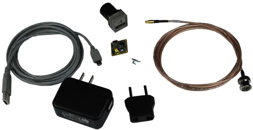
FLIR Camera Controller GUI User’s Guide

                                                                                                       Table of Contents
FLIR Camera Controller GUI ....................................................................................................................... 1
1.0       Document .......................................................................................................................................... 6
   1.1       Revision History ........................................................................................................................... 6
   1.2       Scope ............................................................................................................................................. 6
2.0       Unpacking the Camera ...................................................................................................................... 7
3.0       Basic Accessories.............................................................................................................................. 8
   3.1       VPC Module Accessory ................................................................................................................ 8
   3.2       Camera Link Module Accessory................................................................................................... 9
   3.3       Photon Replicator Board ............................................................................................................... 9
   3.4       Tau Replicator Board .................................................................................................................... 9
   3.5       Quark VPC Module Accessory ................................................................................................... 10
4.0       Connecting to the Camera ............................................................................................................... 10
   4.1       FLIR Camera Controller GUI ..................................................................................................... 10
   4.2       Physical Connection.................................................................................................................... 11
   4.3       Software Connection ................................................................................................................... 12
   4.4       Digital Data via Camera Link ..................................................................................................... 14
   4.5       Troubleshooting the FLIR Camera Controller GUI .................................................................... 16
5.0       Operation of the FLIR Camera Controller GUI .............................................................................. 18
   5.1       Menu Bar .................................................................................................................................... 18
   5.2       Status Tab.................................................................................................................................... 19
   5.3       Setup Tab .................................................................................................................................... 20
      Flat-Field-Correction Mode ................................................................................................................ 21
      External Sync Mode ............................................................................................................................ 23
      Gain Mode .......................................................................................................................................... 23
      SSN ..................................................................................................................................................... 24
   5.4       Analog Video Tab ....................................................................................................................... 25
      Image-Orientation Mode ..................................................................................................................... 25
      E-Zoom ............................................................................................................................................... 26
      Pan and Tilt ......................................................................................................................................... 26
      Polarity/LUT ....................................................................................................................................... 27
      Isotherm LUTs .................................................................................................................................... 28
   5.5       Digital Video Tab (for Tau 1.X) ................................................................................................. 30

102-PS242-02 Rev120                                                     May 2014                                              Page 2 of 65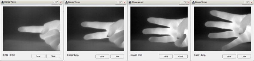
FLIR Camera Controller GUI User’s Guide

  5.6      Digital Video Tab (for Tau 2 / Quark) ........................................................................................ 32
  5.7      Ethernet Controls ........................................................................................................................ 36
  5.8      Image Capture Tab ...................................................................................................................... 36
    5.8.1 Tau 1.X / Tau 2.0 / Quark .......................................................................................................... 36
    Snapshot Viewer ................................................................................................................................. 38
    5.8.2 Tau 2.1 and Later Releases ........................................................................................................ 39
    Max Number of Snapshots.................................................................................................................. 39
  5.9      AGC/DDE Tab............................................................................................................................ 43
    AGC Modes ........................................................................................................................................ 44
    Enhancements ..................................................................................................................................... 45
    Digital Detail Enhancement (DDE) .................................................................................................... 45
    Active Contrast Enhancement (ACE) ................................................................................................. 45
    Smart Scene Optimization (SSO) ....................................................................................................... 45
  5.10     AGC ROI Tab ............................................................................................................................. 46
    AGC ROI Coordinate Values ............................................................................................................. 48
  5.11     Thermal Tab ................................................................................................................................ 48
    Spot Meter Controls ............................................................................................................................ 49
    Isotherms ............................................................................................................................................. 49
    Gain Switch Values............................................................................................................................. 50
  5.12     Radiometry Tab .......................................................................................................................... 51
    External Parameters ............................................................................................................................ 52
    Calibration Parameters ........................................................................................................................ 52
    Blackbody Calibration ........................................................................................................................ 52
  5.13     Image Metric Tab ........................................................................................................................ 53
    Image Metric ROI Coordinate Values ................................................................................................ 54
    Image Metrics ..................................................................................................................................... 54
  5.14     Advanced Tab ............................................................................................................................. 54
    Digital Detail Enhancement (DDE) .................................................................................................... 55
    FFC Utilities........................................................................................................................................ 56
    Shutter-less Gain Switch Calibration .................................................................................................. 56
    FFC Frame Count ............................................................................................................................... 56
    Supplemental Offset............................................................................................................................ 56
    Splash Screen ...................................................................................................................................... 57

102-PS242-02 Rev120                                                  May 2014                                             Page 3 of 65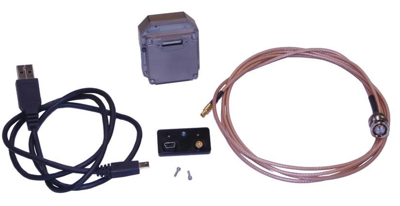
FLIR Camera Controller GUI User’s Guide

   5.15       AGC/DDE (advanced) Tab ......................................................................................................... 57
      AGC Modes ........................................................................................................................................ 58
      Automatic Parameters ......................................................................................................................... 59
   5.16       Bad Pixel Elimination Tab .......................................................................................................... 59
   5.17       Gain Calibration .......................................................................................................................... 61

                                                                                                           Table of Figures
Figure 1: Tau Camera and VPC Module Accessory Kit ............................................................................... 8
Figure 2: Tau Camera Link Module installed on a Tau 640 camera............................................................. 9
Figure 3: Quark Camera and VPC Module Accessory Kit ......................................................................... 10
Figure 4: BNC to RCA Adapter.................................................................................................................. 11
Figure 5: VPC Physical Connections .......................................................................................................... 11
Figure 6: Device Manager showing proper driver installation ................................................................... 12
Figure 7: FLIR Camera Controller GUI Status Tab – Not Connected........................................................ 13
Figure 8: FLIR Camera Controller GUI Connection Window Part 1 ......................................................... 13
Figure 9: FLIR Camera Controller GUI Connection Window Part 2 ......................................................... 14
Figure 10: FLIR Camera Controller GUI Status Tab – Connected ............................................................ 14
Figure 11: FLIR Camera Controller GUI – Digital Tab ............................................................................. 15
Figure 12: Imperx FrameLink Express Software – Camera Parameters Window ...................................... 16
Figure 13: FLIR Camera Controller Error Message ................................................................................... 16
Figure 14: FLIR Camera Controller – Menu Bar........................................................................................ 18
Figure 15: FLIR Camera Controller – Status Tab....................................................................................... 20
Figure 16: FLIR Camera Controller GUI - Setup Tab ................................................................................ 21
Figure 17: Ramp test pattern example for Top Portion of Ramp Image ..................................................... 24
Figure 18: FLIR Camera Controller GUI - Analog Video Tab .................................................................. 25
Figure 19: Look-Up Table Options (Without Isotherms) ........................................................................... 28
Figure 20: Isotherm LUT Scale Example ................................................................................................... 29
Figure 21: Look-Up Table Options (with Isotherms) ................................................................................. 30
Figure 22: FLIR Camera Controller GUI – Digital Video Tab 1 ............................................................... 31
Figure 23: FLIR Camera Controller GUI – Digital Video Tab 2 ............................................................... 33
Figure 24: FLIR Camera Controller GUI – Video Capture Tab ................................................................. 37
Figure 25: FLIR Camera Controller GUI – Snapshot Viewer .................................................................... 38
Figure 26: FLIR Camera Controller GUI – Video Capture Tab Tau 2.1 and later ..................................... 39
Figure 27 – 8-bit Snapshot Management .................................................................................................... 40
Figure 28 – Multiple Bitmap Viewer windows .......................................................................................... 41
Figure 29 – Snapshot Viewer ...................................................................................................................... 42
Figure 30 – Snapshot Viewer with digital data ........................................................................................... 43
Figure 31: FLIR Camera Controller GUI - AGC Tab................................................................................. 43
Figure 32: FLIR Camera Controller GUI – ROI Tab ................................................................................. 46
Figure 33: AGC ROI Example.................................................................................................................... 47
Figure 34: FLIR Camera Controller GUI – Thermal Tab ........................................................................... 48

102-PS242-02 Rev120                                                   May 2014                                           Page 4 of 65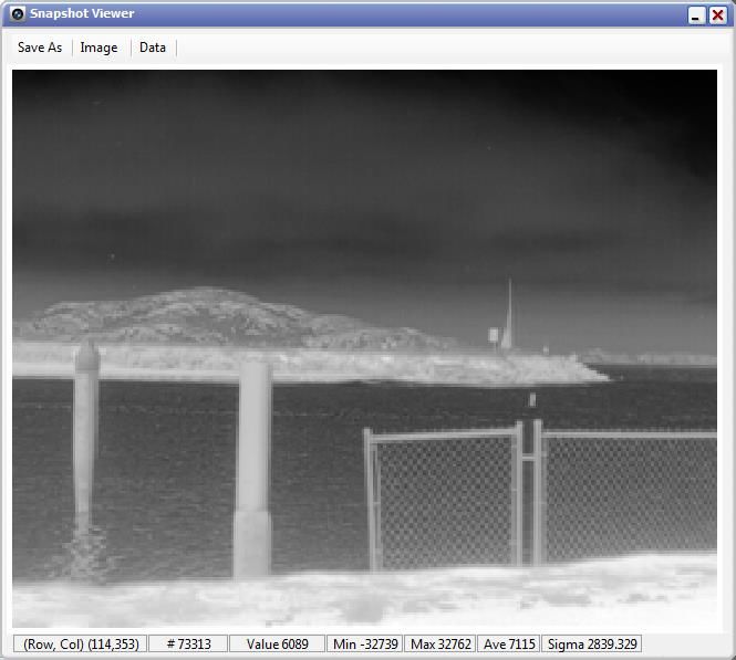
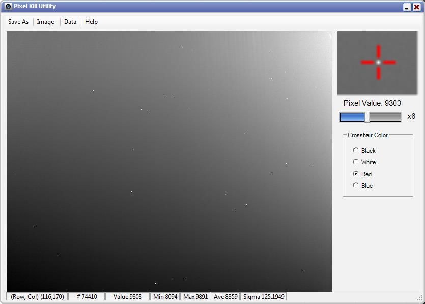
FLIR Camera Controller GUI User’s Guide

Figure 35: FLIR Camera Controller GUI – Radiometry Tab ..................................................................... 51
Figure 36: FLIR Camera Controller GUI – Image Metric Tab ................................................................... 53
Figure 37: FLIR Camera Controller GUI – Advanced Tab ........................................................................ 55
Figure 38: FLIR Camera Controller GUI – AGC/DDE (Advanced) .......................................................... 58
Figure 39: FLIR Camera Controller GUI – Bad Pixel Elimination ............................................................ 60
Figure 40: FLIR Camera Controller GUI – Gain Calibration Tab.............................................................. 62
Figure 41: FLIR Camera Controller GUI – Image Capture ........................................................................ 63

102-PS242-02 Rev120                                       May 2014                                  Page 5 of 65
FLIR Camera Controller GUI User’s Guide

1.0 Document
1.1 Revision History
Version       Date                                               Comments

100         11/2/2011   Initial Release corresponding with GUI version 1.0.0.92

110          6/4/2013   Update for Tau 2.4 Release with GUI version 1.0.0.106

120         5/9/2013    Update for Tau 2.7 Release with GUI version 1.0.0.111

1.2 Scope
The FLIR Camera Controller GUI is freely distributed software that is used to configure and control FLIR
camera cores such as the Tau, Tau 2, Quark, Photon, and others. This User’s Guide includes Quick Start
information for the Tau and Quark as well as detailed descriptions of functions and adjustments for the
camera that can be performed using the FLIR Camera Controller GUI.

102-PS242-02 Rev120                                 May 2014                        Page 6 of 65
FLIR Camera Controller GUI User’s Guide

The FLIR website will have the newest version of this document as well as offer access to many other
supplemental resources: http://www.flir.com/cvs/cores/resources/

Here is a sample of some of the resources that can be found:

Document Title                  Document          Description
                                Number
Tau Quick Start Guide           102-PS242-01      Quick Start Guide for first-time use
Quark Quick Start Guide         102-PS241-01      Quick Start Guide for first-time use
FLIR Camera Controller GUI      102-PS242-02      Detailed Descriptions for functions and adjustments for
User’s Guide                                      FLIR cameras using the FLIR Camera Controller GUI
Tau 2 Product Specification     102-PS242-40      Product specification and feature description
Quark Product Specification     102-PS241-40      Product specification and feature description
Tau 2 Electrical IDD            102-PS242-41      Written for Electrical Engineers to have all necessary
                                                  information to interface to a Tau 2 camera
Quark Electrical IDD            102-PS241-41      Written for Electrical Engineers to have all necessary
                                                  information to interface to a Tau 2 camera
Tau 2/Quark Software IDD        102-PS242-42      Written for Software Engineers to have all necessary
                                                  information for serial control of Tau 2 and Quark
Assorted Mechanical             Various           There are drawings and 3D models for various camera
Drawings and Models                               configurations for mechanical integration
Application Notes               Various           Written for Systems Engineers and general users of
                                                  advanced features such as Gain Calibration,
                                                  Supplemental FFC Calibration, NVFFC Calibration,
                                                  Camera Link, On-Screen Symbology, AGC/DDE
                                                  explanation, Camera Mounting, Spectral Response,
                                                  Optical Interface for lens design, and others.

There is also a large amount of information in the Frequently Asked Questions (FAQ) section on the
FLIR website: http://www.flir.com/cvs/cores/knowledgebase/. Additionally, a FLIR Applications
Engineer can be contacted at 888.747.FLIR (888.747.3547).

2.0 Unpacking the Camera
When unpacking the camera, please heed customary electrostatic-discharge (ESD) sensitive device
precautions including static-safe work station and proper grounding. The camera is placed in a conductive
anti-static bag to protect from electrostatic-discharge damage and safely packaged to prevent damage
during shipping.

Disassembling the camera can cause permanent damage and will void the warranty. Operating the camera
outside of the specified input voltage range or the specified operating temperature range can cause
permanent damage. The camera back is not sealed. Avoid exposure to dust and moisture. The camera
contains electrostatic-discharge-sensitive electronics and should be handled appropriately.

102-PS242-02 Rev120                            May 2014                           Page 7 of 65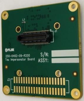
FLIR Camera Controller GUI User’s Guide

3.0 Basic Accessories
The Tau Camera can be simply used with either the VPC Module Accessory (FLIR PN 421-0039-00) or
the Camera Link Module Accessory (FLIR PN 421-0046-00). The Quark camera can be used with the
Quark VPC Module (FLIR PN TBD). These accessories provide an easy way to evaluate the camera core
and access analog and, in the case of the Camera Link Module, digital video during development. These
and other accessories can be found at http://www.flirshop.com.

3.1 VPC Module Accessory
The VPC module accessory includes USB-A to USB-mini B cable for power and communications, USB
power supply, European power adapter, MCX-to-BNC cable for analog video, and mounting screws.

USB Cable           VPC Module                                        Video Cable

                                                             Socket head cap screws
                                                             (M1.6 × 0.35 × 6 mm)

                      Figure 1: Tau Camera and VPC Module Accessory Kit

                     (USB Power Supply and European Power adapter not pictured)

102-PS242-02 Rev120                          May 2014                         Page 8 of 65
FLIR Camera Controller GUI User’s Guide
3.2 Camera Link Module Accessory
The Camera Link module is an expansion board for the Tau camera that matches the functionality of the
VPC Module and adds the ability to access digital data via Camera Link connection. It is possible to use
the Camera Link Module with a Quark camera using a Tau Replicator Board. The Camera Link module
takes CMOS-type digital data from the Tau camera and converts it to Camera Link. In order to use a
Camera Link module for acquisition of data, first enable the CMOS XP Bus Output using the FLIR
Camera Controller GUI. This module does not include a Camera Link cable, frame grabber, or
capture software.
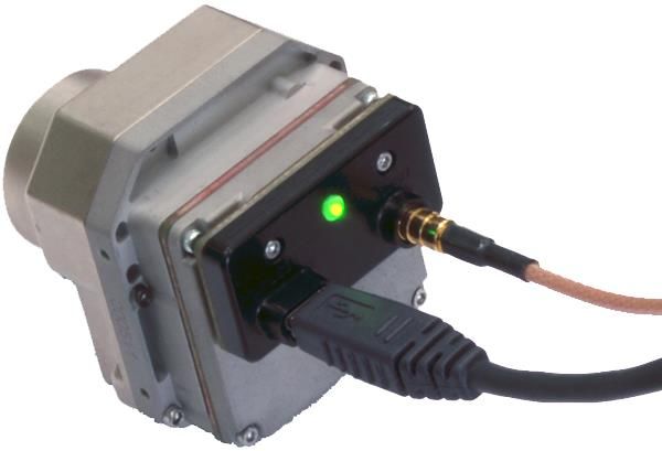
Mounting Screws Power Status Light
M1.6 x 0.35 8 mm SHCS
MCX coaxial
(analog video)
Mini Camera Link
(digital video)
Spacer Mini USB
3 mm x 3.1 mm
Mounting Screws
M 1.6 x 0.35 x 16 mm
Figure 2: Tau Camera Link Module installed on a Tau 640 camera
3.3 Photon Replicator Board
Photon Replicator Board adapts the Tau camera's native 50-pin Hirose
connector to the 30-pin SAMTEC connector used on FLIR's Photon
cameras. The replicator board makes the Tau camera electrically pin-
compatible to a Photon camera, including the provision for operating the
Tau camera over the same input voltage range as the Photon camera: 5-
24VDC. Refer to the Photon 640 User’s Manual for more details including
pin definition.
A cast magnesium spacer and 4 socket-head machine screws are included.
3.4 Tau Replicator Board
Tau Replicator Board (FLIR PN 250-0462-09) adapts the Quark camera's
native high-density 60-pin SAMTEC connector to the 50-pin Hirose
connector used on FLIR's Tau cameras. The replicator board makes the
Quark camera electrically pin-compatible to a Tau camera. Refer to the
Quark Product Specification for more details.
A cast magnesium spacer and 4 socket-head machine screws are included.
102-PS242-02 Rev120 May 2014 Page 9 of 65
FLIR Camera Controller GUI User’s Guide

3.5 Quark VPC Module Accessory
The Quark VPC module accessory includes USB-A to USB-mini B cable for power and communications,
USB power supply, European power adapter, MCX-to-BNC cable for analog video, and mounting
screws.

USB Cable           VPC Module                                        Video Cable

                                                               Socket head cap screws
                                                               (M1.6 × 0.35 × 6 mm)

                     Figure 3: Quark Camera and VPC Module Accessory Kit

4.0 Connecting to the Camera
This section describes installation of necessary software, physical camera connections, and software
connection to the camera.

4.1 FLIR Camera Controller GUI
The FLIR Camera Controller GUI provides communication between a PC and a Tau camera using either
the USB interface or some other means of serial communication.

   1. Computers with an older version of the FLIR Camera Controller GUI should first uninstall it
      using the Windows Uninstall utility via the Windows Control Panel before proceeding with this
      installation.
   2. The newest version of the FLIR Camera Controller GUI can be found at the following URL:
      http://www.flir.com/cvs/cores/resources/software/tau/
   3. Click on the link to download the GUI and save it to the desired computer.
   4. Extract the file using WinZip or other software. This can typically be done by right-clicking on
      the zip file and selecting “Extract”.
   5. Open the directory where the saved file is and double-click “setup.exe”.
   6. Walk through the installation steps.

102-PS242-02 Rev120                          May 2014                         Page 10 of 65
FLIR Camera Controller GUI User’s Guide
7. When the primary installation is completed, a message will prompt to install Silicon Laboratories
drivers. This portion of the installation is necessary for using a USB connection to the camera.
8. The program will install to Start→All Programs→FLIR Systems→Camera Controller GUI
4.2 Physical Connection
This section describes physical connections to the camera and assumes that either the VPC or Camera
Link Accessory Module is being used with the camera.
1. Plug the accessory directly into the rear of the camera. There is a white 50-pin connector that will
mate. Use the included socket head cap screws to secure the expansion board to the camera.
These will insert on either side of the 50-pin connector. The VPC module uses M1.6 × 0.35 × 6
mm screws and the Camera Link module uses M1.6 × 0.35 × 8 mm screws. Using longer screws
could damage the camera.
2. Connect the analog video cable to the VPC or Camera Link Module on the back of the Tau
Camera. There is an MCX mini coaxial connector on the back of the accessories. The opposite
end of the cable has a standard coaxial connector. Connect this to the video input of an analog
monitor. It may be necessary to use a BNC Female to Phono Plug (RCA) Adapter. These are
readily available at electronics stores and allow the camera to be connected to the standard yellow
video input on a monitor.
Figure 4: BNC to RCA Adapter
3. Connect the USB-mini B cable to the VPC Module or the Camera Link Module and the USB-A
end to the computer. (If sound is enabled on the computer, a chime will sound and a notification
that the device has been connected will pop up).
Figure 5: VPC Physical Connections
4. Analog video should appear within a few seconds after connecting the USB cable. Verify analog
video is displayed on the monitor to ensure the camera is properly powered.
102-PS242-02 Rev120 May 2014 Page 11 of 65FLIR Camera Controller GUI User’s Guide
5. Additional Information: Access the Device Manager to verify proper driver installation and
identify communications port. Connection issues are most often caused by attempting to use
the wrong COM Port to connect to the camera.
a. Right-Click on “My Computer” and select “Manage”. This is typically either on the
desktop or available through the start menu.
b. Select “Device Manager” on the left Pane.
c. Expand the tree for “Ports (COM & LPT)”.
d. Note the COM Port number used for Silicon Labs. The following example shows COM3.
Figure 6: Device Manager showing proper driver installation
4.3 Software Connection
This section describes simple communication with the camera using the FLIR Camera Controller GUI
and assumes that the camera is connected to the PC using a USB cable and either the VPC or Camera
Link Accessory Module.
1. Run the FLIR Camera Controller GUI by clicking on the start menu and accessing Start→All
Programs→FLIR Systems→Camera Controller GUI. (The software may take up to 30 seconds to
load the first time.
2. When the GUI first opens, it will display “Not Connected” on the bottom left. The first step is to
connect to the camera.
102-PS242-02 Rev120 May 2014 Page 12 of 65FLIR Camera Controller GUI User’s Guide
Figure 7: FLIR Camera Controller GUI Status Tab – Not Connected
3. Connect to the camera by selecting Tools→ Connection
1
2
3
Figure 8: FLIR Camera Controller GUI Connection Window Part 1
102-PS242-02 Rev120 May 2014 Page 13 of 65FLIR Camera Controller GUI User’s Guide
4. Select Serial (RS-232), select 921600 as the Baud Rate for fastest communication, and click
Next. If there is only one serial communication port on the computer, the button will say Finish.
Figure 9: FLIR Camera Controller GUI Connection Window Part 2
5. Select the Com port seen in the Device Manager and click Finish.
6. The GUI will now automatically connect to the camera and refresh information in the software.
The status LED will turn green and it will display “Connected” on the bottom left. It is also
possible to retrieve the part number and serial number of the camera from this screen.
Figure 10: FLIR Camera Controller GUI Status Tab – Connected
4.4 Digital Data via Camera Link
This section describes digital data acquisition with the Camera Link accessory and assumes that all prior
sections have been successfully completed
1. Connect one end of the Camera Link cable to the camera. The camera connection is a Mini-
Camera Link connector and frame grabbers may use either standard or Mini-Camera Link. It is
possible to purchase cables that have mini connectors on both ends or standard on one end with
mini on the other.
2. The camera must be configured to output CMOS digital data in order for the Camera Link
accessory to work. This can be done by clicking “Video” on the left pane of the GUI, “Digital
Video” tab on the top, and selecting “CMOS” for the XP Bus Output. Select either 14-bit or 8-bit,
102-PS242-02 Rev120 May 2014 Page 14 of 65FLIR Camera Controller GUI User’s Guide
depending upon preference. 8-bit data has the AGC applied and looks similar to the analog video
image. 14-bit data does not have AGC applied.
2
1
3
Figure 11: FLIR Camera Controller GUI – Digital Tab
3. Once these changes are made, it is a good idea to save settings to make them power cycle
persistent. This can be done on the Setup Tab by clicking the “Save Settings” button.
4. The digital data complies with Base Camera Link standards and will be compatible with most off-
the-shelf Camera Link frame grabbers. FLIR has tested the ImperX FrameLink Express frame
grabber (http://imperx.com/frame-grabbers/framelink-express) and the Matrox Solios Camera
Link frame grabber
(http://www.matrox.com/imaging/en/products/frame_grabbers/solios/solios_ecl_xcl_b/). It is
important to note that this module provides access to digital data only and the other portions of
the Base Camera Link specifications are not met. Camera control, external frame sync, and power
through the Camera Link connector are not supported. With simple hardware modifications, it is
possible to route communications through the Camera Link interface rather than through USB. It
is also possible to access the Tau camera’s external sync channel on the Camera Link accessory
through appropriate modification. Please consult a FLIR representative for details on these
modifications.
5. The FLIR Camera Controller GUI allows for control of the Tau camera, but does not support
Camera Link frame capture and so third-party software must be used. The ImperX frame grabber
102-PS242-02 Rev120 May 2014 Page 15 of 65FLIR Camera Controller GUI User’s Guide
includes FrameLink Express software that allows for recording single or multiple images (BMP,
JPG, TIF, and RAW) as well as standard AVI clips. Configuration requires selecting:
“1 TAP, L->R” for the tap reconstruction, selecting the same bit depth that was chosen in the
FLIR Camera Controller GUI in step 2, and clicking “Learn” to discover the number of digital
pixels available.
6. Click Apply and Start Grab
2
1
3 4
Figure 12: Imperx FrameLink Express Software – Camera Parameters Window
7. Note: If the image appears to have very little contrast, the output is likely in 14-bit mode. If that is
the intended setting, use the histogram feature in the frame-grabber software to change the
display range. Otherwise, set the Tau camera to 8-bit Digital Output Mode and the frame-grabber
to 8-bit capture mode. Click “Apply” in the frame grabber software. The camera will now use its
built in AGC functionality that is accessible from the AGC tab in the FLIR Camera Controller
GUI.
4.5 Troubleshooting the FLIR Camera Controller GUI
If the FLIR Camera Controller GUI does not link with the camera, there might be a popup shown below
which indicates that the GUI has not been able to communicate with the camera.
Figure 13: FLIR Camera Controller Error Message
If this is the case, verify the following:
The USB Cable is properly connected to both the computer and the Accessory Module so that
there is a green LED illuminated on the accessory.
102-PS242-02 Rev120 May 2014 Page 16 of 65FLIR Camera Controller GUI User’s Guide
Verify the proper port was selected if it was not detected automatically. Select Advanced, then
Next in the Tools→Connection dialog box. Also, try disconnecting and then re-connecting the
cable to the PC. If the GUI was launched before the cable was connected, close the GUI, connect
the cable, and then re-launch the GUI.
The Baud rate must be set in the Tools→Connection dialog box. The Tau camera supports Baud
rates of 57600 and 921600. The Tau camera automatically detects if the Baud Rate of the first
incoming message is either 57600 or 921600 and will communicate at that Baud Rate until reset.
The Port may be occupied by another application. Shut down any other applications that may be
using the port. Also, multiple instances of the FLIR Camera Controller GUI Program can be
instantiated using different ports so be sure the camera that is interested in being controlling is
actually connected to the physical port that was verified in the Device Manager in Section 3.2,
step 5.
Verify that the camera is powered by checking that the camera is producing an image on an
analog monitor. On cameras with a shutter installed, listen for the sound of the FFC at startup.
There will be a clicking sound as the shutter is moved in and out of the field of view in the first 5
seconds after power is applied.
If the GUI says SWIR Camera Controller on the top, try to use Camera→Select to select LWIR-
MWIR rather than SWIR. If this option is not present, the GUI will need to uninstall using the
Windows Uninstall utility via the Windows Control Panel and delete the Program Files directory
(C:\Program Files (x86)\Flir Systems\Camera Controller GUI). The latest .NET Framework will
also need to downloaded and installed from Microsoft (http://www.microsoft.com/net/download).
It is best to use the client profile from the web. Once this is updated, install the Camera Controller
GUI and use Camera→Select to select FLIR rather than SWIR.
If serial communication cannot be initiated with the camera after verifying these items, refer to the
frequently asked questions (FAQ) at http://www.flir.com/cvs/cores/faqs/tau/all/. Additionally, a FLIR
Applications Engineer can be contacted at 888.747.FLIR (888.747.3547).
102-PS242-02 Rev120 May 2014 Page 17 of 65FLIR Camera Controller GUI User’s Guide
5.0 Operation of the FLIR Camera Controller GUI
This section describes operation of the FLIR Camera Controller GUI and explains adjustments that can be
made to the camera.
5.1 Menu Bar
The FLIR Camera Controller GUI has a classic menu bar where drop down menus are displayed.
Figure 14: FLIR Camera Controller – Menu Bar
File: The file menu has the option to Exit. This will close the GUI and
can also be performed by clicking the x on the top right corner.
View: Select Log to display a log at the bottom of the GUI. This does
not display all commands sent to the camera, but rather displays
connection information.
Click Refresh to refresh the GUI. This can also be done with the F5
function key on a keyboard and is useful for fields like FPA
temperature that will be changing with time.
Camera: Select Connect to connect to a camera using the same
communications parameters that were used previously. If connection
cannot be established, it will ask to retry or open the connection
wizard.
Select Disconnect to open the COM port that the GUI is occupying and
disconnect from the camera. This can be useful if using other software
to communicate with the camera.
The Select submenu allows selection of different camera types. The
type “FLIR” can be used for Quark, Tau 2, Tau, and Photon.
Tools: Select Clear Log to clear the log that can be displayed using the
View menu.
Select Connection to open the connection wizard. This allows the
ability to configure communication settings such as COM Port and
baud rate.
Select Settings to configure the GUI. It is possible to configure the
GUI to automatically connect at startup using the previous settings,
allow multiple instances to be open at once, or change communication
timing parameters.
102-PS242-02 Rev120 May 2014 Page 18 of 65FLIR Camera Controller GUI User’s Guide Help: Open the Camera Controller User Guide in the default pdf viewer. The latest version of this document installs in the Program Files directory. Select SDK Documentation to view help information for the Photon SDK that can be used with Tau, Tau 2, Quark, Quark 2 and Photon. The SDK does not install with the GUI, but must be purchased separately. Select About Camera Controller to open a separate window with version information for the GUI and the camera. About: The GUI Framework is the version of the GUI. The Main App is the software version of the camera. The version in the example is v15.20.15.9. The firmware is v15.22.14.12. Click Details to view versions for each individual dll in the GUI. 5.2 Status Tab When the FLIR Camera Controller GUI successfully links to the camera, the window shown below will be visible. At the bottom of the application window, there is the Camera and FPA status. The GUI provides six tabs allowing for camera control as described below. 102-PS242-02 Rev120 May 2014 Page 19 of 65
FLIR Camera Controller GUI User’s Guide

                           Figure 15: FLIR Camera Controller – Status Tab

Camera Part #: This indicates the specific camera configuration connected. Please refer to the
appropriate Product Specification for details understanding the part number. If the first two digits of the
Part Number are 41, 42, or 43, the camera connected is a FLIR Tau 1.X (previous releases of Tau 320 and
Tau 640). If the first two digits are 46, 47, 48, 66, 67, 68 the camera connected is a FLIR Tau 2. If the
first two digits are 50, the camera connected is a FLIR Quark.

Camera Serial #: This is the serial number of the camera currently connected to the FLIR Camera
Controller GUI.

FPA Temperature: The camera’s Focal Plane Array (FPA) temperature.

Note: The connection status, Camera status, Camera Part #, and FPA Size are displayed at the bottom of
all tabs.

5.3 Setup Tab
The Setup tab, shown below, provides the ability to set and save basic settings in the camera.

102-PS242-02 Rev120                             May 2014                           Page 20 of 65
FLIR Camera Controller GUI User’s Guide
1
2
Figure 16: FLIR Camera Controller GUI - Setup Tab
Flat-Field-Correction Mode: Flat field correction (FFC) is a process
whereby off set terms are updated to improve image quality. This is
done by presenting a uniform temperature (a flat field) to every
detector element. While imaging the flat field, the camera updates
correction coefficients, resulting in a more uniform array output.
During an FFC, the analog and digital video is frozen for less than 500
ms, and resumes automatically thereafter. For cameras that include
internal shutter, the shutter is closed and then reopened during this
time.
Repeating the FFC operation often prevents the imagery from appearing “grainy”. This is especially
important when the camera temperature is fluctuating, such as immediately after turn-on or when ambient
temperature is drifting. FFC can be controlled manually at any time using the Do FFC command button.
After any FFC event, it is possible to store the currently-applied map to non-volatile memory via software
command, in which case that map will be applied automatically at the next power-up. This feature,
commonly referred to as Non-Volatile Flat Field Correction (NVFFC), is particularly useful for
shutterless configurations. If the camera is in automatic FFC mode, it will resume the FFC schedule five
seconds after startup. Use of this feature requires access to the Advanced Tab. Refer to Section 4 or the
NVFFC Application Note for more details.
The camera provides three FFC modes:
102-PS242-02 Rev120 May 2014 Page 21 of 65FLIR Camera Controller GUI User’s Guide
Auto: In the Automatic FFC mode, the camera performs FFC whenever its temperature changes
by a specified amount or at the end of a specified period of time (whichever comes first). When
this mode is selected, input windows are available in the FLIR Camera Controller GUI for
specifying the temperature change and the number of frames that trigger automatic FFC. The
temperature change is specified in degrees C, with valid values in the range 0 to 100 in 0.1 degree
increments. The time period is specified by counting analog video frames between FFC events
(Start counting after the last FFC is complete) with valid values in the range 0 to 30,000 frames.
Setting the FFC Interval to 0 frames means that elapsed time will not be used to trigger an FFC.
The second set of Auto FCC parameters labeled Low Gain apply to cameras that support Low
Gain Mode. If there is an NVFFC saved, the camera will load this correction at startup and will
resume normal operation after five seconds.
Note: FLIR recommends using the factory default values for the two automatic-FFC parameters if
possible. These values were selected to maintain a high degree of image quality over all camera operating
conditions. Automatic mode is not recommended for shutterless configurations because there is no
assurance that the core will be imaging a uniform source when it initiates an automatic FFC.
Manual: In Manual FFC mode, the camera does not perform FFC automatically based on
specified values of temperature change or expired time. The FFC will be performed once upon
startup if there is no saved NVFFC, then again using the internal shutter whenever they do FFC
button is clicked. If there is an NVFFC saved, this will be loaded at startup. When transitioning
across camera temperatures of 0°C 40°C, and 65°C, a Do FFC command is recommended in
order to maintain image quality.
External: In External FFC mode a uniform source must be placed in front of the camera. This
feature is useful if there are lens or lens mount non-uniformities that are not corrected by an
internal FFC. The camera will not perform an FFC process on startup, but it will load a saved
NVFFC if present. Many customers have found that the palm of their hand or a table is an
adequate uniform source to perform an External FCC.
The camera displays an on-screen symbol called the Flat Field
Imminent Symbol prior to performing an automatic FFC
operation. It can be seen in the image to the right as the blue
square in the upper right of the video output. By default, it is
displayed 60 frames (2 seconds in LVDS) prior to the FFC
operation. The duration of the FFC Imminent Symbol can be
set using the FFC Warn Time setting in the Analog Video Tab.
Setting the Warn Time to less than 15 frames turns off the
warning (see Section 5.4).
102-PS242-02 Rev120 May 2014 Page 22 of 65FLIR Camera Controller GUI User’s Guide
External Sync Mode: FLIR cameras provide the ability to either accept or
output a frame synchronization pulse. Refer to the appropriate Electrical IDD for
more information on pin definition and pulse timing.
Disabled: The camera runs at its native frame rate and it will not output a frame synchronization
pulse.
Slave: The camera will accept a frame synchronization signal on the interface connector. The
camera output will be frozen if the camera is in slave mode and no external synchronization
signal is received.
Note: External sync should only be used for digital output. Performance is greatly
reduced when using external sync for analog video.
Master: The camera will output a frame synchronization signal on the interface connector when
configured as a master.
Gain Mode: Some FLIR cameras support low gain mode. This mode will provide a
higher intrascene range, but will lower the sensitivity. When the camera is in Auto
Mode, it will switch between high and low gain modes based on the gain switch values
configured on the Thermal Tab (see section Error! Reference source not found.).
Operating Mode: The camera will freeze the analog frame imaged when Frozen
is selected. Live video will cease and the frozen frame will persist. To return the
camera to live video, select Real-Time video mode. “Frozen” cannot be saved as
the power-on default state.
Save Settings: After using the FLIR Camera Controller GUI to change Camera modes and settings to
desired values, use the Save Settings button to store the current selections as new power-up defaults. The
next time the camera is powered; the camera will remember these saved Settings. If the Save Settings
button is not clicked, any changes made via the FLIR Camera Controller GUI will be valid only for the
current session. Cycling power to the camera will revert to the previously saved settings.
Note: The Save Settings button applies to changes made anywhere in the GUI, not only the Setup Tab.
Factory Defaults: The Factory Defaults button restores the camera’s settings to the initial values specified
in the FLIR factory. To save the factory default settings as the power up defaults, first click the Factory
Defaults button, then click the Save Settings button.
Reset Camera: The Reset Camera button performs a soft reset that restarts the camera software.
Test-Pattern: A Test-Pattern mode is provided to adjust display properties and/or for diagnostic purposes
(for example, to verify the core is providing a valid output). The Test-Pattern mode will not persist over a
power cycle.
Off: No test-pattern is provided in this mode. This is the normal operation mode.
102-PS242-02 Rev120 May 2014 Page 23 of 65FLIR Camera Controller GUI User’s Guide
Ramp: In this mode, the test pattern shown below and in the Color/LUT section that follows is
provided at the analog and digital data channels.
Pix(0,0) = 0 Pix(639,0)=639
Pix(383,25)=16383
Pix(384,25)=0
Figure 17: Ramp test pattern example for Top Portion of Ramp Image
(Digital values shown apply to the optional 14-bit digital data stream.)
The above ramp pattern repeats 19 times in the complete 640 × 512 image. For a 320 x 256 resolution
camera, the pattern will repeat 4 times.
Note: The ramp test pattern is intended primarily for verifying the output of the digital data channel. The
pattern will not necessarily look as shown above when displayed on an analog video monitor, particularly
if an Automatic Gain Control (AGC) mode other than Automatic is selected. The above image is a
horizontal slice of the full displayed image.
Scratch Pad: Tau2 cameras support an internal scratch pad
that can be used to save notes in the field for testing
purposes.
SSN: The Tau2.7 and Quark 2.0 release support Silent
Shutterless Non-Uniformity Correction (SSN). There are
multiple presets for different use cases. The original use case was for shutterless cameras and as the
usefulness of the algorithm was observed, the use cases were extended to cameras with a shutter. SSN is a
spatial pattern noise reduction algorithm that uses motion within a scene to determine if a pixel is noise or
true scene information. If a pixel is determined to be noise then a correction map will increment its value
towards returning the pixel towards the local average.
There are four preset for both use cases of shutter and no shutter: no
motion, low motion, medium motion and high motion. The user must
determine the use case that their camera will be used in and select a
preset accordingly. The largest differences between the presets are
what constitutes motion and the maximum allowed correction for the
algorithm. High speed vehicles would find the most benefit from the
high motion default while a fixed pole security application would be
considered a no motion scenario. Choosing an appropriate default will
help avoid any possible image artifacts.
102-PS242-02 Rev120 May 2014 Page 24 of 65FLIR Camera Controller GUI User’s Guide
5.4 Analog Video Tab
The Analog Video tab on the FLIR Camera Controller GUI, shown below, provides the ability to
configure the camera’s analog output.
2
1
Figure 18: FLIR Camera Controller GUI - Analog Video Tab
Image-Orientation Mode: Two Image-Orientation mode
selections are provided. Select one or both to change the
orientation of the video image.
Invert: The normal image is flipped vertically. The pixel on the upper-left corner of the detector
array is displayed on the lower-left corner of the video display in Invert mode. This is the
recommended mode when the core images the scene via a vertical fold mirror or when the camera
is mounted upside down. Invert applies to all output channels.
Revert: The normal image is flipped horizontally. The pixel on the upper-right corner of the
detector array is displayed on the upper-left corner of the video display. This is the recommended
mode when the core images the scene via a horizontal fold mirror, when used in a rear-facing
application intended to simulate the view through a rear-view mirror, and when the camera is
mounted upside down. Revert applies to analog and BT.656 for Tau 1.X (older configurations of
Tau 320 and Tau 640), and to all output channels (i.e., also CMOS, and LVDS) for Tau 2 /
Quark.
Note: If the camera is in Automatic or Manual FFC mode, an FFC will be performed automatically when
the image orientation mode is inverted. Adjusting image orientation should always be followed by a flat-
field correction in all modes.
102-PS242-02 Rev120 May 2014 Page 25 of 65FLIR Camera Controller GUI User’s Guide Zoom: Tau1 and Quark 1 cameras have built in discrete steps of zoom capability with on screen symbology. For cameras with 160 x 128 resolution, the maximum zoom level is 2x. For cameras with 324 x 256 resolution or 336 x 256, the maximum zoom level is 4x. For cameras with 640 x 512 resolution, it is possible to zoom to 8x. The zoom level is a function of the current analog output resolution. For example, a Tau 320 in NTSC has an output of 320 x 240. 2x zoom mode will use the center 160 x 120 and interpolate to achieve an NTSC output resolution of 640 x 480. E-Zoom: The Tau 2.1 and Quark 2.0 later releases provide the capability for continuous zoom. The user can adjust the zoom with the arrows or enter the desired zoom multiplier in the box provided. The maximum zoom is based on the resolution of the camera as described above. Pan and Tilt: The user may pan left or right and tilt up or down while zoomed. The zoom level is a function of the current analog output resolution and defaults to interpolating the center pixels described in the Zoom section above. The Pan and Tilt shifts this interpolated window by up to 40 pixels in any of the four directions: up, down, left, or right. Fine: Enabling Fine will limit the Pan and Tilt to 20 pixels in all directions to provide a smaller step in pan/tilt on the order of a single pixel. Center: Pressing the Center button will return the Pan and Tilt coordinates back to the center of the image. FFC Warn Time: The camera displays an on-screen symbol called the Flat Field Imminent Symbol prior to performing an automatic FFC operation (See Section 5.3). Use this function to set the number of analog video frames (33ms NTSC, 40ms PAL) during which the warning will be displayed. The time period, specified in frames, can range from 0 to 30,000 frames. The factory Setting of 60 frames equates to a two second warning in NTSC. Setting the FFC Warning to less than 15, turns off the warning. Video On/Off: This feature allows the ability to turn off the analog video output which will result in power savings (approximately 75mW). Video Standard: Choose the video standard for the system the camera will be used in. It is necessary to perform an FFC after changing the video standard. This can be done using the Do FFC button on the Setup Tab. Changing the video standard affects the operating frame 102-PS242-02 Rev120 May 2014 Page 26 of 65
FLIR Camera Controller GUI User’s Guide

rate of the camera in both the analog and digital output.

Averager: Some FLIR cameras are equipped with a 60Hz sensor. This
control will not be present for cameras that do not support this
feature. In averager-enabled mode, the core performs automatic
“smart” averaging of pairs of frames from the detector array to
achieve a 30Hz NTSC or runs the sensor at 50Hz and averages to
achieve 25Hz PAL. The averager operation is designed to reduce blur
by only averaging a given pixel’s output if the difference from one
frame to the next is small enough to be considered noise. Bypassing
the average will allow for 60Hz digital data to be captured.

Video Color: Choose color mode or monochrome mode for the
analog video. In monochrome mode, color encoding is not used and
video low-pass filtering is disabled in the analog output signal, which
results in slightly higher bandwidth data to the display system. This
mode can be used to improve image sharpness when color palettes
and color symbols are not required.

Note: For transmission of the analog video channel, a coaxial cable with 75 ohm characteristic impedance
is required. The analog output is current mode and a 75 Ohm termination is required. This termination is
present in most display devices.

Analog Symbology: Tau 2.7 and Quark 2.0 and later releases support the option to disable symbology in
the analog output. This would remove all symbology from being overlaid in the analog output including
FFC imminent, zoom symbology and radiometric symbols if the camera is being used in a radiometric
mode.

Polarity/LUT: The camera detects and images the temperatures in a
given scene. Within the camera, these temperatures are mapped (as
determined by the AGC algorithm selected) to a range of 0 to 255
values. In a black and white display mode, this range is converted to
shades of gray with 0 being totally black and 255 being totally white.

The 0 to 255 gray shades range can also be referenced to a Look-Up
Table (LUT) permanently stored in the camera to convert the scene
to a color video image. Different LUTs are available to change the
appearance of the displayed image. The most common selection is
either White Hot (hotter objects appear brighter than cooler objects in the video display) or Black Hot
(hotter objects appear darker than cooler objects). Since the difference between these two modes simply
reverses the choice of darker or lighter for temperature extremes, this is sometimes referred to as Polarity.
Other color LUTs are available as shown below.

102-PS242-02 Rev120                              May 2014                           Page 27 of 65
FLIR Camera Controller GUI User’s Guide
Options shows each of the LUTs as displayed in Test Pattern Ramp Mode starting with the upper left:
White Hot, Black Hot, Fusion, Rainbow, Glowbow, Ironbow1, Ironbow2, Sepia, Color1, Color2, Ice Fire,
and Rain. Select one of these LUTs from the pull-down menu to view the image displayed using the
chosen LUT. Setting the Polarity/LUT mode will not affect the CMOS or LVDS digital data output for
releases prior to Tau 2.4. Beginning with the Tau 2.4 release, color for 8-bit CMOS and LVDS can be
enabled on the Digital Video Tab (see section 5.6).
Cold Cold Cold Cold
Hot Hot Hot Hot
White Hot Black Hot Fusion Rainbow
Cold Cold Cold Cold
Hot Hot Hot Hot
Glowbow Ironbow1 Ironbow2 Sepia
Cold Cold Cold Cold
Hot Hot Hot Hot
Color1 Color2 Ice Fire Rain
Figure 19: Look-Up Table Options (Without Isotherms)
Simple experimentation with this feature while viewing the video image will provide familiarity.
Remember to click the Save Settings button on the Setup Tab to save the LUT settings as the default at
power-up.
Isotherm LUTs: Updated Isotherm LUTs were introduced with the
Tau 2.4 release. The applied LUT is changed when Isotherms are
enabled on the Thermal Tab (see section 5.11 for more details).
Polarity / Palette: In Tau 2.4 and later, the Isotherms have an updated
drop down menu that has the associated names in it with an attached –
Iso to help distinguish between which state the Isotherms are in.
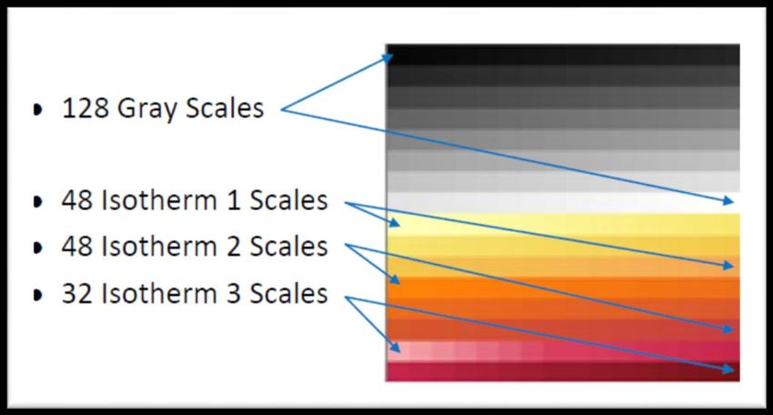
Isotherm LUT Scale: The camera detects and images the temperatures
in a given scene. Within the camera, these temperatures are mapped
(as determined by the AGC algorithm selected) to a range of 0 to 255
values. In WhiteHotIso mode, this range is converted to shades of gray
with 0 being totally black and 127 being totally white. The first
102-PS242-02 Rev120 May 2014 Page 28 of 65You can also read