Evolution of a digital twin with an ethylene plant as an example - Concept and implementation
←
→
Page content transcription
If your browser does not render page correctly, please read the page content below
© Siemens 2020

                  Chemicals

                    Evolution of a digital
                    twin with an ethylene
                    plant as an example
                    Concept and implementation

White   Edition
Paper   01/2020                                  siemens.com/chemicals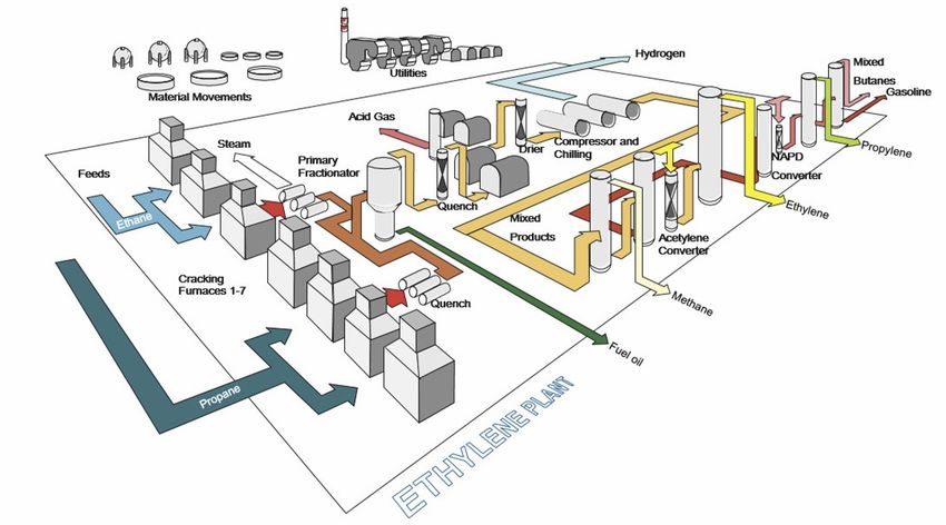
© Siemens 2020

Content                                                       Introduction

                                                              The article describes a concept for the development and
                                                              integrated use of a digital twin over the entire lifecycle of a
    1      First steps with a digital twin            3
                                                              process plant. Various aspects of a digital twin are defined
    1. 1   Models and simulation in the lifecycle of a        and described. Possible benefits of a digital twin in successive
           plant                                       3      phases of its lifecycle are discussed in detail. The concept is
    1. 2 Landscape of the models                      4       realized in form of a demonstrator using the example of a
                                                              steam cracker for ethylene production [36].
    1. 3 Vision                                       6
    2      Example application - Steam cracker        5
    3      Design and evolution of a digital twin     9
    4      Use of the digital twin                   13
    4. 1 Engineering                                 13
    4. 2 Plant operation                             14
    4. 3 Re-engineering of the digital twin          18
    5      Summary                                   19
    6      References                                20
    7      Authors                                   21

2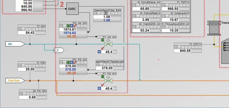
© Siemens 2020

Evolution of a digital twin

1    First steps with a digital twin                               Like the real system, the digital twin develops across the plant
                                                                   lifecycle and integrates the currently available data and
The term „digital twin“ itself evokes a wide range of associa-
                                                                   knowledge bases in a step-by-step, integrated way. It not only
tions. With human twins, we think of common inherited
                                                                   describes the system‘s behavior, but solutions for the real
traits, similar characteristics and characters, and the often
                                                                   system are also derived from it [1].
astonishing parallels in their ways of life. Although there is
still a large discrepancy between the interest in digital twins    The individual components of a digital twin are largely state-
(> 500 million Google links) and the number of real applica-       of-the-art already today. New perspectives come from the
tions, the term „digital twin“ is more than just a buzzword in     approach of integrating the individual models and software
the process industry. There are indeed many different con-         tools into an integrated, semantically coupled system, via the
cepts, but also initial approaches to concrete implementations.    various hierarchical levels of a plant and via the various
                                                                   phases in the lifecycle of a plant.
At first glance, the large number of different types of digital
twins appears to be confusing. Depending on the viewpoint          1. 1 Models and simulation in the lifecycle of a
of the observer, typical terms such as
                                                                        plant
◾ Product digital twin
                                                                   Each simulation can be considered as a virtual experiment
◾ Automation digital twin                                          with the goal of better understanding a system [2]. The
◾ Production digital twin                                          system characteristics are modeled in a sufficiently accurate
◾ 3D digital twin                                                  mathematical representation and calculated using common
◾ Asset digital twin                                               computer programs. The creation of a simulation model is
                                                                   thus always purpose-oriented and context-specific, i.e. it
◾ Process digital twin
                                                                   serves to answer one or more special questions. To this end,
◾ etc.                                                             a simulation model can, for example, describe the physical,
can be found in literature, lectures and conferences.              chemical, energetic and/or IT behavior of a system over time
                                                                   [3]. Simulations are more or less frequently used nowadays in
A digital twin of a process plant as an integrated concept
                                                                   all phases of the plant’s lifecycle and can be compiled into the
covers three core points: The digital twin of the product, the
                                                                   following four groups:
digital twin of the production plant and the digital modeling
of the performance of the product and production.                  ◾ Simulation for virtual commissioning
The functional scope of a digital twin essentially depends on      ◾ Virtual commissioning simulation
its purpose. In the process industry, this can be everything       ◾ Training simulation (OTS: operator training system)
from the safety analysis, product simulation or the optimization   ◾ Simulation during operation
of the production process, right up to economic benefit            These four use cases of simulations are shown in Figure 1
formulation.                                                       over the lifecycle of a process plant.
Parts of an integrated digital twin are among others, planning
data from the design and engineering phase, plant data from
the operating phase, and descriptions of the plant behavior in
the form of models. The individual simulation models that
belong to the digital twin are specifically tailored to the
planned use and satisfy the respective requirements for
accuracy in this regard.

                                                                                                                                  3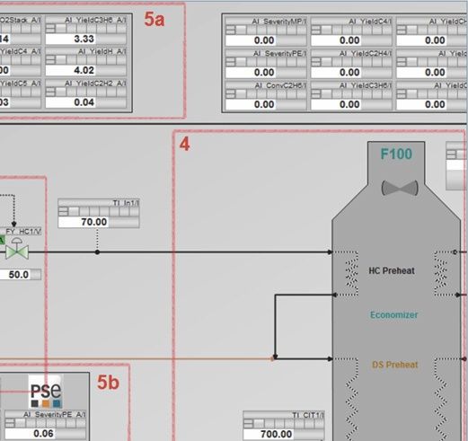
© Siemens 2020

Evolution of a digital twin

    Plant lifecycle

        Conceptual         Basic                  Detailed                                                                        Maintenance and
                                                                     Setup                    Commissioning    Operation
        design             planning               design                                                                          modernisation

    1                 Basic Design                                                        3                   Operator Training

                                              2      Virtual commissioning and simulation-based               4 Operation-associated decision
                                                                    engineering                                     support and optimization

Figure 1: Use cases of simulations in the lifecycle of a process plant

Design simulation [4, 5]: Use of a steady-state process                         Depending on the intended application spectrum the simulation
simulation for the plant engineering and design. The result is                  component requirements for user interface, model accuracy,
represented by energy and mass balances and mass balance,                       model details and validity differ greatly.
the Process Flow Diagram (PFD) and data sheets for the
                                                                                Operation-related decision support and optimization [13, 15]:
individual units and devices. Sometimes dynamic process
                                                                                The use of simulations in the operating phase is very wide.
simulations are already used in this phase. This enables
                                                                                That can vary from soft sensor for monitoring and control
modeling of the transient behavior between operating points
                                                                                applications up to model predictive controllers. The operator
of the process for example, for a better design of start-up and
                                                                                can receive support for his future decisions, by examining
shut-down behavior.
                                                                                various production scenarios before active intervention in the
Virtual commissioning and simulation-based enginee-                             process.
ring [6–10]: After finishing the plant equipment design, the
automation system design will be performed. For a safe and                      1. 2 Landscape of the models
efficient operation of the plant, the distributed control system                The mathematical models available for the digital twin are
play a key role. Therefore a correct functioning of the system                  highly diverse. Depending on the functional requirements in
is essential. The use of simulation support in this phase by                    the intended life-cycle phase application, the degree of model
signal and function testing of the engineered process control                   accuracy can range from moderate for examination procedure
system against virtual plant models. This simulation models                     controls and control strategies up to exact replica of process
represent the behavior of all devices that communicate with                     dynamics required for tuning control parameters. In Table 1,
the automation system. The configuration of the automation                      different components of a digital twin are displayed as lines,
program that will later be used in real operations should be                    with the respective purpose in the lifecycle being categorized
the one that is tested. To this end, it will either be run on the               in columns.
real hardware (a programmable logic controller (PLC)) as
                                                                                In Table 1 the functional requirements of a digital twin, broken
so-called hardware-in-the-loop configuration, or on an emulated
                                                                                down by requirements for different plant components (lines)
hardware, as so-called software-in-the-loop configuration [11].
                                                                                and different units or phases in the life cycle of the plant
Since 2013, the GMA expert committee 6.11 has been dedicated                    (columns). The first lines make statements about the respective
to working out VDI/VDE guideline 3693 [12] on the topics of                     model requirements. The following abbreviations are used:
virtual commissioning. Test configurations, test methods and                    CPM: Control Performance Monitoring, RLT: Remaining Life
model types which are used in the context of virtual commis-                    Time prediction, CM: Condition Monitoring, XR: VR/AR
sioning are introduced in sheet 1 of this guideline.                            Support, MPC: Model-Predictive Control, RTO: Real Time
                                                                                Optimization, EKF: Extended Kalman Filter or soft sensor,
Operator training [13, 14]: The goal of a training simulation
                                                                                PLC: Progammable Logic Controller; OS: Operator System;
is to prepare operating personnel risk-free, efficient and
                                                                                ES: Engineering System; EDD: Electronic Device Description;
realistic for their future tasks. This encompasses both working
                                                                                SFC: Sequential Function Chart; APF: Advance Process Functions
with the process control system and with the process itself.

4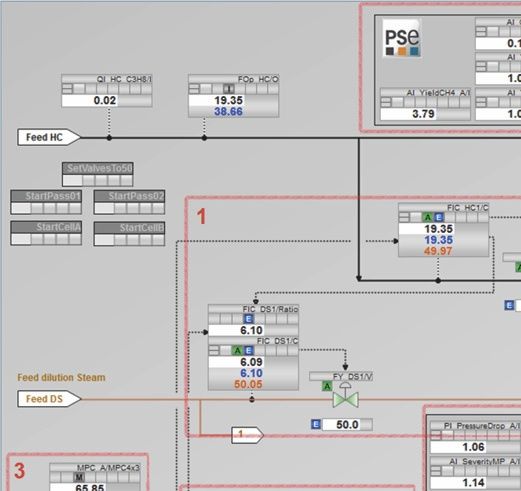
© Siemens 2020
Evolution of a digital twin
Category Real twin Digital twin Software Planning Commissio- Operation Main-
programs ning tenance
Model types Examples
Basic engineering, concept
Maintenance planning
Virtual commissioning
Detailed engineering,
Automation concept
Production planning
Real commissioning
Optimization, APC
operation modes
Configuration
Training
Model Model accuracy ++ ++ + – + ○ + ++ – +
requirements
Model details ++ ++ + – + – + + – ○
Scope + + ++ – ++ ○ ++ ++ ○ +
Units Reactor, Steady- gPROMS,
cracker, state model AspenPlus, X X RTO
column, etc. Pro-Il
Dynamic model SIMIT, Matlab
X
(coarse, wet run)
Dynamic model Matlab, PID
simplified and tuner, CPM X X X MPC CPM
linearized
Dynamic model gPROMS, ACM
X X X EKF
(precise)
Dynamic model gPROMS
X X RTL
(expanded by wear)
FEM (flow, thermo- Star-CCM+
X X
dynamics, CFD)
Material flow models Preactor X
Components Valves, pumps, Characteristic curve, SIMIT, Excel,
X X X X X CM
motors data, fields ValveApp,
Sensors Device models SIMIT, EDD X X X X CM
Automation PLC hardware Emulation SIMIT-VC X X X
technology
PLC software Copy of the PLC ES project
X X X
software
PLC user Copy of the PLC Virtual OS
X X X
interface interface
Documents Process flow Object-oriented PFD COMOS Feed
X X X
diagram (PFD)
P&ID Object-oriented P&ID COMOS P&ID X X X
Data sheets EDD, @eclass X X X X
Recipes, Emulated PLS SIMATIC Batch,
X X X X X X X
procedures APF, SFC
Signal lists Link between parts COMOS,
of the digital twin HW-Config, X X X
SIMIT
Layout 3D model COMOS
X X XR
planning Walkinside
Measured data Measured data OSI PI,
archive InfoPlus.21, X X X CPM
Historian
Table 1: Functional requirements of a digital twin over plant lifecycle
5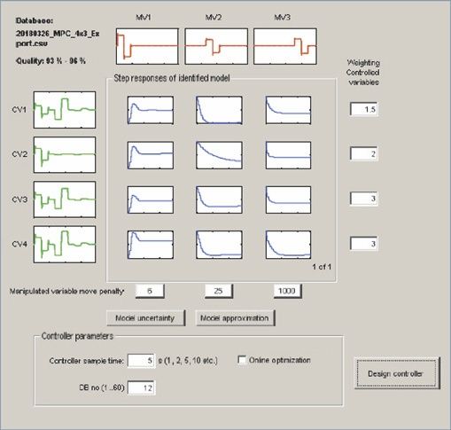
© Siemens 2020

Evolution of a digital twin

Reading example: A dynamic simplified linearized model of a           The role that simulation plays in the product and production
unit (reactor, cracker) can be used in the plant life cycle for the   lifecycle was examined in the section on discrete production
following tasks: Planning of the automation concept                   in [16]. Of course, industrial practices are still far away from
(PID controller design), virtual commissioning, real commis-          the integrated use of simulations. How the integrated use of
sioning (using or updating the model for PID tuning), optimiza-       simulations in the lifecycle of processing plants has been
tion in the operating phase (MPC), and control performance            implemented to date and how it can be implemented more
monitoring (CPM). For this application the model will be              comprehensively, was worked out in detail in [17].
transferred into different software tools respectively updated,       The following image of the future is depicted in [18,19]:
for instance Matlab, PID-Tuner, MPC-Configurator, CPM.
                                                                      „In the future, simulations will be systematically used and will
An exemplary use of the model within the framework of an
                                                                      be an integral part of the normal engineering and operating
APC application (e.g. MPC) sets greater requirements to the
                                                                      processes over the entire life cycle of process plants. The basis
model accuracy and details than an application in mainte-
                                                                      for the engineering and operation of a plant will be a virtual
nance planning (CPM). The exact dynamic model is realized in
                                                                      depiction of the plant. Decisions will be evaluated and made
gPROMS and can be used for planning of procedural alternatives
                                                                      based on the virtual plant. New plants will first be planned
(recipes) within detail engineering, for planning automation
                                                                      and developed virtually, and even in existing plants, no
concepts (for example loop-paring: allocating of actuators to
                                                                      changes will be made before a preceding check in the virtual
control loops), and in operation phase for training purpose
                                                                      plant. Once developed, models will be reused and refined
(operator training) and model based soft sensors (EKF).
                                                                      over the course of the lifecycle. This will be supported by
The virtualized representation of a device, system or even an         available exchange and co-simulation standards. The configu-
entire plant requires the description of the real behavior using      ration of the simulation models is done modularly to allow
models. For simulation and modeling software, there is a              reuse and an efficient layout. Simulation models (modules)
comprehensive offering on the market, often specialized for           can be connected to each other in the sense of „plug-and-
devices, machines, instruments and plants, such as pumps,             simulate“. Models are provided by manufacturers of the real
distillation towers, polymerization reactors or steam crackers.       components as standard feature to use them for the layout of
Yet, the integrated use of the models in a digital twin leads to      the overall virtual plant. The process of creating models is
a new level in usability of the model, thanks to the high             easy and the first models for the virtual plant can be derived
degree of connectedness.                                              from existing planning data (especially for existing plants for
                                                                      later creation of the virtual plant). This is possible on the basis
In information technology, for the modeling of complex
                                                                      of integrated information and data management between
systems a distinction is made between static type level (class
                                                                      planning, simulation and operating data. A connection
definition) and dynamic instance level (objects). For example,
                                                                      between real and virtual plants allows continuous optimizati-
a pump is a device with static properties defined by type,
                                                                      on of the virtual depiction and support in answering opera-
which generates a reproducible pressure or flow rate in a
                                                                      tions-associated questions. Thanks to the parallel operation
value-added process. Instance-specific values are dynamically
                                                                      of the virtual and real plants, continuous optimization relative
assigned to the properties at each individual real pump.
                                                                      to factors such as costs, time, energy consumption and
Comprehensive domain know-how from process and automa-
                                                                      resource consumption of the real plant is possible. A highly
tion technology as well as the corresponding software programs
                                                                      fluctuating demand can best be answered by the virtual
are required for creating models.
                                                                      plant, because predictive simulation calculations can always
1. 3 Vision                                                           ensure the ideal operating state. In addition, the engineering
                                                                      and operating know-how is always up-to-date and can be
Considering the listed advantages, the question arises why
                                                                      called up by all participants in the form of the models and
simulation are not integrated and by default used over the
                                                                      data of the virtual plant. Finally, simulation is part of the
entire plant lifecycle today. In addition, today‘s use cases are
                                                                      training at institutes of technology and is a widely accepted
often isolated from one another, i.e. models and experiences
                                                                      technology and method.“
are seldom reused. The literature already contains suggesti-
ons on how simulations can be used in a more integrated               This article takes on this image of the future and puts it in the
way. Bausa and Dünnebier [4] are investigating, for example,          context of the discussions about the „digital twins“, which
how mathematical models from the design phase can be                  have been going on for some years. In addition, the concrete
reused for optimization of the later operating phase.                 example of an ethylene plant shows how far this vision can
                                                                      be implemented already today.

6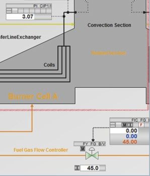
© Siemens 2020

Evolution of a digital twin

2     Example application - Steam cracker                                        The cracking furnace is a tubular reactor with several separate
                                                                                 coils in which the mixture is heated up to temperatures of
A „steam cracker“ (cracking furnace) is given in this article as
                                                                                 approx. 840 °C. The long-chain molecules are thermally
an example of a practical application of the general concepts.
                                                                                 cracked within fractions of seconds.
Steam cracking is a method in the petrochemical industry in
                                                                                 In Figure 2 a simplified steam cracking furnace with one tube
which long-chained hydrocarbons (naphtha, but also ethane,
                                                                                 coil is shown. COT („Coil Outlet Temperature“) and TMT („Tube
propane and butane) are converted by means of thermal
                                                                                 Metal Temperature“) describe temperatures that are relevant
cracking in the presence of water vapor into short-chained
                                                                                 for the control concept described later in the digital twin use
hydrocarbons such as ethylene, propylene and butane.
                                                                                 chapter.
A cracking furnace is one of the most complicated units in
petrochemical plants. It is used to manufacture intermediate
products, which are mainly processed to become plastics
(such as polyethylene), paints, solvents, or insecticides.

                                                                      Exhaust Gas

                                                                                          NOx
                  Hydrocarbon (educt)                                                     CO
                                                                                          O2

                  Dilution Steam

                                                                                        TMT           COT
                                                                                         TI            TI
                  Air

                                                                                                            Cracked Gas (product)

                  Fuel Gas

Figure 2: Schematic representation of a steam cracking furnace with tube coils

                                                                                                                                               7
© Siemens 2020
Evolution of a digital twin
Due to the high through-puts and the economical importance The cracking furnaces are situated at the beginning of the
of a cracker, any potential optimization should be exploited. material flow in an ethylene plant, refer to Figure 3. Several
Unavoidable plant downtimes, for such things as decoking for large cracking furnaces are operated simultaneously. In the
example, must be minimized. downstream, multi-stage separation process with distillation
The following challenges present themselves to the solution columns, steam separators, coolers and similar apparatus,
concept [20]: various products are separated.
◾ The yield of the main products depends on many influen- The starting point for all solutions ideas is a rigorous dynamic
cing factors and is therefore best controlled via a corres- process model of the cracker [22]. The thermodynamic and
ponding multivariable control procedure (MPC). The yield chemical phenomena inside the coils are described with
cannot, however, be measured directly at the outflow of balance equations for coil sections. The number of segments
the cracking furnace, but only in summary form and with is smaller than for a typical finite element model (FEM), to
a long delay after cooling. To be able to respond to changes
achieve real-time capability of the model. Nevertheless, the
as quickly as possible directly in the cracker, the current
cracker model is a system of differential algebraic equations
value must be determined via a model-based soft sensor.
The current intensity of the cracking process is described (DAE) with a total of more than 10,000 equations.
using the term „Severity“, quantified by the ratio of specific
concentrations of substances at the cracker output.
The severity can also only be estimated by a soft sensor
during runtime.
◾ Due to the high temperatures, caking occurs on the pipes.
This is called coking. The yield of the cracker drops, depen-
ding on the degree of coking. The current extent of coking
must be determined to plan cleaning measures.
The coking requires «pass balancing» around all of the
«passes» (tube bundles), which are heated up by a burner
cell, to maintain the same coil outlet temperature (COT)
despite different degrees of coking.
Figure 3: Overview of an ethylene plant [21]
8© Siemens 2020
Evolution of a digital twin
3 Design and evolution of a digital twin Once completed, the utilization phase commences in
accordance with the defined functionality (see definition
To build a digital twin, it is important to understand the
phase). Effective and long-term deployment requires
general principles of production processes, operations, site
constant, automated comparisons between the real and
infrastructure, and energy management systems to be able
virtual plants.
to correspondingly define the scope of the digital twin
(modeled parts of the plant), the functional requirements Although process engineering production processes are
(“What should the digital twin be able to do?”), the architecture diverse, individual and complex, they usually consist of a
(software, hardware and interfaces), and the maintenance combination of simpler units (“unit operations”), which can
and support measures (“How do I keep the digital twin be represented in a general diagram, as shown in Figure 4.
up-to-date?”). This includes raw material supply and preparation, synthesis,
product separation and refinement, product handling and
A digital twin project is typically made up of the definition
storage, emission reduction, a comprehensive infrastructure
phase, project implementation, and the operating phase.
that interconnects the units, an energy system that generates
Specification of the project takes place in the definition phase steam, electrical energy and compressed air for use in the
taking all parameters into account. This includes in particular process and cooling systems, and a management system that
a description of the plant scope and the functional require- ensures the flow of the process in all scenarios.
ments. This information is summarized in a general specification
The core of each procedural production process, for which
sheet. Technology suppliers from the process industry are
raw materials are converted by means of a chemical reaction
consulted here based on their accumulated technical experti-
in intermediate or end products, is the synthesis. It is therefore
se and experience.
quite common for the digital twin to be used specifically for
The subsequent project handling includes development of the synthesis in the first implementation phase.
the architecture, implementation and commissioning of the
digital twin.
Infrastructure
Energy
Product
Handling & Product
Raw Material Product Storage
Supply Separation &
Synthesis
and Refinement
Preparation Emission
Abatement Waste
Management Systems
Figure 4: General diagram of procedural production process [23]
9© Siemens 2020
Evolution of a digital twin
If this diagram is applied to the example of the plant repre- Needless to say, the creation of a digital twin which can be
sented here for the production of ethylene (Figure 3), the utilized throughout the entire cycle of the plant must be
digital twin of the synthesis comprises the plant section of evaluated taking costs and benefits into account. Due to the
the cracking furnaces. An important question here is: which numerous application options, however, it should be safe to
functional requirements are to be fulfilled by the digital twin? assume that creation and continuous utilization will ultimately
Typical examples of the application range are shown already prove beneficial in the long run. Process optimization within
in Table 1. operation of the plant alone, for example, will deliver appre-
ciable savings which would be impossible to estimate at the
Once the issue of respective simulations has been clarified,
beginning of the design phase.
the suitable software packages can now be selected. There is
an increasing, almost unmanageable number of programs for In the example of the steam cracker considered here, a profit
the simulation of each special application. Some are general of between USD 25 and 50 million is achieved each year for a
and very flexible, others are highly specialized, some come large ethylene plant [22], as well as savings of up to 20% in
with ready-made libraries of process engineering components engineering costs [24].
and units, others allow you to write your own code to suit
The software tools required for the digital twin to create the
your needs. The scope of requirements and the choice of
steady-state and dynamic process model, the plant configu-
software programs play a significant role in the configuration,
ration and the automation project are derived from the
implementation and maintenance costs for the digital twin.
specification.
If, for example, the digital twin is to be used both for optimi-
zing the control concept and for configuring process-related Figure 5 visualizes the general considerations of the system
system changes while at the same time ensuring the inte- architecture, which are subsequently mapped to the shared
gration of the models, considerable time, financial and software landscape of Siemens AG and PSE (Process Systems
personnel resources are required. If simulation models are Enterprise, London) and concretized.
developed individually for one purpose only, an individual
cost-benefit assessment is required. In many use cases the
result will be negative so that no simulation model is created,
which thus cannot be used for further tasks.
Simulations tool(s)
Process Flowsheet Design Dynamic Model
- Open Loop -
Steady - state Model Dynamic Model Process; VC
Mass-, energy balances, mass-, heat - Closed Loop -
transfer, phase equilibrium, reaction Dynamic Model
kinetics, etc. conceptual control design
Signals, Sensors, Aktuators
conceptual
design
Plant design Process Control System
Soft
P&ID Automation sensor
Distributed Control
Instrumentation, DCS
Process-and P&ID System APC
distributed Configuration
Process Flow Sheet Instrumentation control system, Virtual Controller, HMI
(PFD) Diagram electification, etc. RTO
Plant layout design Automation Design DCS operation
Tool Model Scheme Result Standard Engineering Reverse-Engineering
Figure 5: General workflow for creation of the digital twin
10© Siemens 2020
Evolution of a digital twin
The plant design is at the beginning of a plant‘s lifecycle. The models or data created at this point in the engineering
An initial digital process twin is created here with the simulation are used to create another digital twin via the existing inter-
software, based on existing system knowledge and actual faces, the so-called digital instrumentation twin. This is used
experiences from publications. This digital twin is used for the to validate the created automation program within the frame-
conceptual design of the plant and its components. For a work of virtual commissioning and to identify malfunctions
cracker, for example, this includes defining the economically prior to actual commissioning. Depending on the require-
most efficient and safe reactor design. The dimensioning of ments, compression of the process information in the form of
reactor- size, -wall thickness, pumps, heat exchangers and highly accurate behavior models leads to an increase in the
buffer tanks is also performed using steady-state simulation test quality during virtual commissioning.
models.
After all the necessary tests have been carried out, the plant
In the further course of the engineering, the digital process approaches actual commissioning. During this phase, training
twin generated with the simulation software is transferred to systems for operators of the plant („Operator Training
the plant planning tool in the form of a process flow diagram Systems“, OTS) can be used so that the plant behavior is
and thus forms the basis for the digital plant twin. This is then internalized in advance. This ensures that the plant personnel
successively expanded with further plant-relevant aspects are trained for both normal operation and for the occurrence
such as sensors, actuators and controller structures. of failures, as well as minimizing reaction times. The intricacy
The ultimate outcome of this forms the Piping and Instrumen- of how such an OTS is designed is also decisive here.
tation Diagram (P&ID). The analysis and validation of the A „high-fidelity OTS“ necessitates an extremely detailed
controller concepts takes place in parallel with a dynamic process model. Rather than having to create this from the
simulation model, i.e. the two digital twins are continuously beginning again, as was previously required, the information
synchronized with each other. Changes in the digital plant form the various digital twins can be drawn upon in this
twin have a direct effect on the digital process twin. Errors in regard. Ideally, the existing process model of the simulation
the plant design can be identified and rectified at an early software (digital process twin) is simply coupled to the exis-
stage from simulation of the dynamic model. ting simulation model of the digital instrumentation twin
(co-simulation).
In the further course, the digital plant twin will be expanded
in the plant planning tool to include the automation compo- Further optimization potential should be gleaned once the
nents such as process control system, process instrumentati- plant is up and running. From the planning phase, for example,
on and operator panels, and the structural planning will be it is sufficiently known at which mass flow rate the compo-
enriched with more detailed engineering information. nents must be mixed, heated or cooled, so that the setpoint
For this purpose, assets (valves, motors, etc.) are identified values for the basic controllers can be set according to these
within the plant planning, similar assets are grouped into specifications. However, changes in process behavior due to
types and stored as such in the plant planning tool. aging processes and wear or a changed market environment
(for example fluctuating raw material and energy prices)
From the preparatory work in the process engineering system
mean that the optimum operating point of the plant can
planning tool, the plant structure is transferred to the engi-
change over time. In this case too, existing models can be
neering tool of the process control system, thus automatically
used to continuously optimize the plant. Rigorous models can
laying the foundation for automation hardware and software
be used for static real-time optimization of the complete plant
engineering. The hardware (automation and operator panels,
or for dynamic optimization of individual units.
instrumentation and I/O devices) is configured and para-
meterized with the engineering tool on the basis of existing The implementation of the concept described is possible
plant planning. Additionally, corresponding automation logic thanks to the collaboration [25] between Siemens and PSE.
is created in the software for the various asset types. Further Figure 6 shows an overview of the tools and software
down the line, this is synchronized with the digital plant twin components used.
in the plant planning tool. The created type descriptions are
instantiated for mass data engineering in accordance with
the specification in the plant planning tool and the corres-
ponding instances are then generated in the engineering tool
at the level of the automation logic.
11© Siemens 2020
Evolution of a digital twin
Real Twin
off-line
on-line COMOS
Data connection gO:RUN on-line Model
applications
CPU Plant Automation & Operation
PCS 7
Process
Engineering gPROMS Modeling Coupling VC PCS 7
connection VC OS
Library Mapping Steady State Model RTO
Engineering manual engineering
„conceptual design“ Optimizer PLCSIM
Mechanical Design Engineering
connection
(models) OPC
PFD, P&ID Dynamic Model
NLMPC AS PIMS
CCM+-STAR
„closed loop“ gRPOMS
Shared M.
Soft Sensor
Dynamic Model SIMIT Unit ES
Simulation „open loop“ HW-& SW-Engineering
…
Engineering
Dynamic Model Scenario Design
SIMIT SF
Digital Twin DCS/SIS
(virtual commissioning)
Engineering Device Model HW/Signals
EIC Engineering Process Design, Engineering, Training and Optimization of Plant
Figure 6: Vision of a digital twin
A detailed process simulation (process twin) which is created An essential part of the overall concept is realized in the form
as early as the conceptual design stage in gPROMS (PSE) of a software demonstrator for use on the steam cracker. In
continues to be used throughout the entire lifecycle. this regard, PSE provides the process model in the gPROMS
The engineering in COMOS is thus incorporated from the simulation software. Siemens supplies the automation system
process flow diagram through to the complete P&ID diagram. including basic control and MPC in the SIMATIC PCS 7 process
Following conclusion of the procedural engineering, all control system. The high-fidelity simulator gPROMS is connected
required information is transferred to SIMATIC PCS 7 to the to PCS 7 via the SIMIT Simulation Platform from Siemens and
engineering system. In addition, the field level is displayed in an OPC UA communication. The various application aspects
SIMIT so that virtual commissioning can take place directly. are described in more detail in the following chapter.
For further application as an operator training system, the
gPROMS model is coupled with SIMIT in order to enable
realistic training. A simulation-based static and/or dynamic
optimization is also possible with utilization of the simulator.
12© Siemens 2020
Evolution of a digital twin
4 Use of the digital twin Replicating the process behavior (physical behavior) will also
prove practical for testing of the SFCs. This can be done, for
After the implementation phase is completed, it is possible
example, with the simulation of a cold commissioning, in
to work with the digital twin to answer specified tasks in
which the behavior of the process is observed as long as only
engineering and operational area of the plant.
water is pumped through the system as a medium and no
4. 1 Engineering chemical reactions take place yet. Extremely detailed process
models are required wherever the controller is to be parame-
Typical segments of engineering where the digital twin can
terized. The connection of existing process models via
be used are in the design of basic engineering of process
co-simulation can be exceptionally advantageous in this
equipment and the automation system, virtual commissioning
regard. At least for the Hardware-in-the-Loop configuration,
of the control system and the training before start-up a new
the simulation system must be capable of supplying and
plant or reconfiguration of existing plant.
processing signals within the stipulated real-time. Simulation
models are also implemented as part of the control program
Design on the automation hardware in a special Software-in-the-
The goal of the simulations in the design of a process engi- Loop configuration, eliminating the need for additional
neering plant is the creation, verification and refinement of simulation tools [28]. However, these advantages are offset
the plant design. The focus is on considering the actual by certain disadvantages: The control program is altered
process. Controllers are only available in simplified form, if at following testing, simulation-specific functions such as a
all, as part of the process model. It is imperative that different virtual time (faster or slower than real-time), snapshots
process drafts can be compared with one another in order (saving model states) or even co-simulations may be difficult
that the most suitable can be selected respectively. The to attain with the resources of the automation system, if at
accuracy of the simulation must be sufficiently good to be all. Test cases which could be created automatically [29] and
able to make the process-related decisions correctly. A static automatically executed would be beneficial in ensuring the
process simulation is sufficient for the design of plants in most efficient test possible.
steady-state continuous operation; a dynamic process simula-
tion must be used for the simulation of start-up and shut- Training (OTS)
down processes and the transients between operating points.
The objective of training simulation is to prepare the opera-
It may prove practical to combine models of different tools,
tors for their tasks as effectively as possible. This encompas-
either by exchanging models or via co-simulation [26].
ses both interaction with the process control system (ideally
on the basis of the original operating screens and programs),
Virtual commissioning as well as familiarization with the reaction of the process
The aim of virtual commissioning is to achieve a fully tested itself. Training for interaction with the process control system
automation system wherever possible [27]. The main focus is can be realized in accordance with the selected modeling
on testing the implemented PLC application software, developed depth based on the model which was created for virtual
unique for every system. For testing e.g. signal routing, commissioning. For training related to the process itself, it is
continuous function charts (CFC), sequential function charts necessary to model this in detail. Such models are thus also
(SFC), faceplate and pictures for operator station (OS) and ideal as training for limit situations, start and stop procedu-
alarms, a simulation model can be used, which operates the res, and emergency scenarios. It is therefore essential that
complete communication interface between automation and training scenarios can be created and adapted. In addition,
field and is connected to the real (hardware-in-the-loop) or it must be possible to asses, compare and verify the perfor-
emulated (software-in-the-loop) control hardware. It is mance of trained personnel [30]. Moreover, particular atten-
imperative for both setup scenarios that at least the commu- tion must also be afforded to the didactic concept when
nication behavior of the field devices (actuators and sensors) devising the scenarios [31].
is replicated in the simulation model.
13© Siemens 2020
Evolution of a digital twin
4. 2 Plant operation Equipment Modules: (1) Ratio control for feed educt and
steam (instance oft the template Ratio-Control), (2) Ratio
Typical segments of plant operation where the digital twin
control for furel gas and combustion air (instance of templates
can be used are in the design of virtual sensors, advanced
“GARC= Gas-to-Air Ratio Control), (3) MPC-Instance according
process control-, optimization- and maintenance systems.
to Figure 8, (4) Part of furnace in digital twin simulated by
The various application aspects are shown in more detail in
dynamic gPROMS model, (5) Visualization of the calculated
the following chapter and are shown in Figure 7 using the
results of the soft sensor, which is also based on a rigorous
Cracker Demonstrator.
dynamic gPROMS model.
Figure 7: P&ID of steam cracker as display in Operator Station of SIMATIC PCS 7, including Faceplates for Soft-Sensor and MPC
14© Siemens 2020
Evolution of a digital twin
Soft sensor APC
Soft sensors represent an important application of a digital All higher level control procedures which go beyond standard
twin during the operation phase. A soft sensor estimates an single-loop PID controllers come under the APC keyword
unknown process variable based on a model of the process („Advanced Process Control“). In view of the task definition
and other available measured variables. Common examples for a multivariable control on the steam cracker, model-based
include the Luenberger state observer [32] or the Kalman predictive control (MPC) seems to be the most appealing
filter [33], which are based on dynamic process models in the option [35]. All predictive controllers are based on the basic
form of differential or difference equations. As all variables principle IMC (Internal Model Control): A dynamic model of
are known in the simulation model, the variables being the controlled system is part of the controller and is used
estimated can be obtained directly. during runtime to predict future process behavior in a defined
prediction horizon. The model knowledge of the digital twin
Reverting back to the digital twin of the system will ensure
can be used as a basis for the process model of predictive
that a model-based soft sensor does not have to be modeled
controllers. Essentially, there are three procedures open to
anew for each application. A dynamic process simulations
you in this regard:
which is already available must be analyzed and, where
necessary, the sub-model separated for the process section 1. For a non-linear predictive controller, a (sub)model is
for which a soft sensor is required. It is then only necessary to used from the dynamic simulation model of the digital
parameterize and to validate the soft sensor algorithm using twin. However, this must generally be simplified conside-
process data. rably in light of the real-time capability of the controller,
as numerous simulations of the process model can be
The effort afforded for implementation of a soft sensor is calculated throughout the entire prediction horizon in
worthwhile if the estimated variable is essential for process each scanning step of the MPC. Non-linear MPC concepts
control. Estimated variables can be applied for monitoring therefore present special challenges due to the process
tasks in which the exothermic reaction is estimated, for model, but also due to the dynamic online optimization.
example, and monitored for a maximum permissible value to 2. A model can be derived for a linear predictive controller
avoid unfavorable or dangerous process states [34]. Direct through numeric linearization around an operating point
control of estimated variables is also possible. Thus, in the within the simulation software. The advantage of linear
example given the yield can be measured, but only after MPC concepts lies in the considerably reduced effort
several steps of the procedure have been executed. The computing effort. It is thus possible to implement the
MPC directly in the process-level component of a control
resultant dead time which is many orders of magnitude
system, with the respectively associated advantages
greater than the actual process dynamics renders direct
regarding availability, operator control and monitoring,
control of the measured yield impossible. The estimated yield usability, and expenditure.
at the output of the cracking furnace, however, is provided
3. Step change attempts are performed with the simulator.
free of dead time via the soft sensor and may thus be used
The artificially generated training data is then used for
for direct control. the identification of linear models with the configuration
tool of the MPC. This procedure has the advantage that it
can be executed with the existing software
infrastructure.
15© Siemens 2020
Evolution of a digital twin
MPC concept for steam cracker majority of the time is to be found in restriction of the mani-
pulated variables. The MPC therefore has three degrees of
Precise apportionment of the functional scope in a multilevel
freedom, of which only two are usually applicable.
solution concept with basic automation, soft sensors, MPC
and RTO is the result of intense discussions between the The aim of closed-loop control on the one hand is to maintain
project partners at PSE and Siemens. The MPC concept com- the quantity of ethene and propene as high as possible,
prises four controlled variables for one half of the furnace, all whilst at the same time attaining a high conversion rate of
of which originate from the soft sensor. Any existing thermal the reactants to ensure a minimum of wastage. Limit values
couplings between both halves of the furnace are not repre- must be respected at all times to ensure safety of the system.
sented in the simulation model and are thus not in the MPC. The throughput of the desired product is selected as the first
controlled variable (Figure 8). However, the ethylene
The following are provided to the MPC as manipulated variab-
throughput could only be measured with a greater dead time
les:
for the separation section of the overall cracker system.
◾ Supply setpoint combustion gas The throughput is therefore calculated using the product
◾ Supply setpoint hydrocarbons (reactant) from the supplied quantity of hydrocarbons and the ethylene
◾ Ratio „process steam to reactant“ yield, which is estimated by the soft sensor. The soft sensor
variable conversion rate of the supplied ethane is applied as
The MPC specifies the setpoint for the GARC (Gas-to-Air Ratio
a second controlled variable. Since only two degrees of
Controller), and thus indirectly the burner inflow made up of
freedom are effectively available due to the restricted number
combustion gas and air. The ratio between combustion gas
of manipulated variables, additional control variables can no
and air is regulated at a lower-level by the GARC. The ratio of
longer be regulated precisely to their setpoint. In order that
process steam to reactant supply can be influenced by the
a safe system state can be guaranteed, the COT („Coil Outlet
MPC as a third manipulated variable, however, the permissib-
Temperature“) and TMT („Tube Metal Temperature“) are
le range for this ratio is very limited. This shows that the third
therefore maintained by the MPC in tolerance bands as third
MPC manipulated variable has minimal influence and the
and fourth controlled variables.
MPC 4x3
Ethylene throughput CV1 MV1 SP Fuel Gas Feed
Yield Ethane CV2 MV2 SP HC Feeds
COT CV3 (deadband) MV3 Ratio DS/HC
TMT CV4 (deadband) MV4
Figure 8: MPC 4x3 configuration with ontrolled variables (CV) and manipulated variables (MV)
16© Siemens 2020
Evolution of a digital twin
The following requirements are defined for plant operation: Manipulated variables are the ratio factors with which the
feed setpoints for individual coils are calculated from the
◾ Maintain Conversion Rate Ethane at setpoint
overall feed.
◾ Run Ethylene Throughput to defined setpoint
◾ Maintain COT within specified range This concept is compatible with the previous higher-level MPC
concepts for the overall cracker if the mean COT is influenced
◾ Maintain TMT below critical upper limit
by the total reactant inflow as previously. The same amount
Dead zones are specified for the controlled variables 3 and 4. of additional controlled and manipulated variables is added.
Should either of these temperatures stray from the permissible In principle, the Pass Balancing can be implemented with
range, the high weighting of the control deviation of these single-variable controllers, as long as cross-influences bet-
variables is brought to bear. The MPC performs the following ween neighboring pipe strings are negligible and the summary
task from the viewpoint of the plant operator: Determine the effect of the Pass Balancing is neutral.
suitable setpoints for supply of reactant, process steam and
combustion gas to achieve a defined production rate with the Plant-wide optimization
necessary conversion rate, and to ensure that the temperatures
(COT and TMT) remain within the specified range. The con- Many different system components are integrated in a large
cept can be expanded with measurable disturbance variables, petrochemical plant for the production of ethylene and propy-
for example composition of the reactant and the heat value lene. The various system components of an industrial steam
of the combustion gas. cracker plant for thermal cracking and subsequent separation
are shown schematically in Figure 3. The requirement and the
market environment of the individual reactants and products
may therefore change from day to day. In order that an
optimum operating profit can be achieved, the operating point
of the plant must be adapted to the market environment.
This problem can be solved as an optimization problem based
on the digital twin. To this end, the optimum setpoints are
calculated for each individual system component under
defined boundary conditions using a specified target function
and the strict model of the complete plant. For example,
a target function for maximization of profit for each unit of
time can be structured as follows:
The profit is calculated from the difference between the
proceeds anticipated for the n various products p and the
costs for the k various reactants e. This simple calculation
could also incorporate additional boundary conditions, such
Figure 9: Model of steam cracker in MPC-Configurator of SIMATIC PCS 7 as energy costs or maintenance planning.
The optimum values of the controlled variables calculated in
For design the MPC, the MPC engineering toll (Figure 9) from this manner are applied to specify optimum setpoints for
SIMATIC PCS 7 was used. individual process units for a specific period of time, referred
to as stationary operating point optimization. Optimum
The MPC concept can be combined with the lower-level „Pass
transition from one stationary state to another is a task for
Balancing“. A weighted COT mean value of all coils is calcula-
the lower-level controller structures, for which a dynamic
ted in this regard, where the respective feed is applied as a
process optimization may be applied (Figure 10).
weighting factor. Controlled variables are then the deviation
of individual COT values from this mean value; no dead zone
is used here.
17© Siemens 2020
Evolution of a digital twin
Figure 10: Furnace optimizer for 7 cracking furnaces Figure 11: Run-Length-Prediction Screen
Maintenance 4. 3 Re-engineering of the digital twin
With the increasing production time, coking (caking of soot In the course of plant operation, the plant undergoes constant
deposits) occurs in cracking furnaces which crack long-chained changes. Whether this be simple wear-related replacement of
hydrocarbon molecules. This causes the plant behavior to a component or optimization of the process following a con-
change continuously throughout the production time, until the version. All constituents of the digital twin must be constantly
coking has built up to such an extent that the corresponding updated in every scenario. For this it is essential to provide
cracking furnace must be shut down and cleaned. To minimize automatically usable interfaces between the participating tools
the downtimes required for cleaning work, it makes sense to (see Figure 6), as a manual adaptation is not only unrealistic in
adapt the mode of operation to ensure that coking is kept to an terms of cost. The error rate is also far too high with manual
absolute minimum. compensation using completely different tools.
The capital which has already been invested in the digital Moreover, it is advisable to verify the behavior of simulation
process twin during the plant design phase can also be used models regularly with real measuring date. On the one hand,
again here. The strict plant model is used to perform „What-If“ this will allow unwanted changes in the plant behavior to be
experiments. These scenarios are helpful, for example, in detected in accordance with the validity range and quality of
maximizing the production time (remaining service life until the model. On the other hand, changes intentionally imple-
cleaning is required) or for optimum planning of the mainte- mented in the plant behavior must be replicated in the simu-
nance time. lation. Although such simulation adjustments can be suppor-
ted by process identification and parameter estimation
If the production conditions change due to bottlenecks in
techniques, they should always be checked and validated by
resources or due to volatile raw material prices, the economic
an employee.
balance can be improved by these kinds of experiments using
a digital process twin (Figure 11).
18© Siemens 2020
Evolution of a digital twin
5 Summary
The article describes numerous facets of integrated utilization
of a digital twin for procedural systems. The concrete imple-
mentation of the various applications using the example of a
steam cracker makes it possible to understand the interplay
between the various components of the digital twins and the
various tools involved, and clearly shows the benefits of an
overall consideration of the digital twin. This results in
numerous benefits which are clearly visible in the application
example - starting with the plant configuration and the use of
simulations for the process design to virtual commissioning,
all the way to process optimization. So there is the hope that
in the future no isolated cost-benefit estimate for the creation
of a simulation model for tasks in the operating phase is
necessary anymore because all the required information and
models are not only available in the form of the digital twin,
but are also always up-to-date, and thus directly usable for
the real twin.
19© Siemens 2020
Evolution of a digital twin
6 References
[1] Rosen, R., Boschert, S. und Sohr, A. (2018): Next generation digital [20] Sinatra, A., Biscaro, M. et al. (2003). Polimeri europa olefin plant
twin. atp magazin, 60(10), (pp. 86-96). doi:10.17560/atp.v60i10.2371 maximizes benefits from advanced solutions.
[2] VDI Richtlinie 3633, Blatt 1. (2010). Simulation von Logistik-, Material- https://library.e.abb.com/public/e99b8721064863b485256f-
fluß- und Produktionssystemen. VDI:www.vdi.de 9d00746eec/PE_OlefinPlantMaximizeBenefit.pdf
[3] Bungartz, H. J., Zimmer, S., Buchholz, M., und Pflüger, D. (2009). [21] Buffenoir, M.H. (2007). A greener chemistry - 120 million tons of
Modellbildung und Simulation: eine anwendungsorientierte Einfüh- Ethylene per year. Why, what for, & how “greener”?.
rung. Springer-Verlag https://slideplayer.com/slide/4449028/
[4] Bausa, J., Dünnebier, G. (2006): Life Cycle modelling in the chemical [22] Process Systems Enterrise Limited. (o.J.) gOlefins Cracking Monitor.
industries: Is there any reuse of models in automation and control? In Virtual multisensor for real-time measurement of key cracking furnace
Computer Aided Chemical Engineering (Vol. 21, pp. 3-8). Elsevier operational values.
[5] Nagl, M. (2008): Collaborative and distributed chemical engineering. https://www.psenterprise.com/solutions/golefins/crackingmonitor
From understanding to substantial design process support. Results of [23] European Commission. (2003). Integrated pollution prevention and
the IMPROVE project (Vol. 4970). Springer Science & Business Media control (IPPC): Reference document on best available techniques in
[6] Barth, M., Fay, A. (2013): Automated generation of simulation models the large volume organic chemical industry.
for control code tests. Control Engineering Practice 21(2), (pp. 218–230) http://eippcb.jrc.ec.europa.eu/reference/BREF/Ivo_bref_0203.pdf
[7] Barth, M., Fay, A.¸ Wagner, F., und Frey, G. (2010): Effizienter Einsatz [24] Tauchnitz, T. (2010). Leittechnik und Engineering wachsen zusammen.
Simulations-basierter Tests in der Entwicklung automatisierungstech- https://www.chemanager-online.com/news-opinions/interviews/
nischer Systeme. Tagungsband Automation, (pp. 47-50) leittechnik-und-engineering-wachsen-zusammen
[8] Drath, R., Weber, P., und Mauser, N. (2008). Virtuelle Inbetriebnahme [25] Siemens AG. (2018). Siemens aquires PSE.
– ein evolutionäres Konzept für die praktische Einführung. https://press.siemens.com/global/en/pressrelease/
VDIBERICHT, 2032, (pp. 73) siemens-plans-acquire-process-systems-enterprise
[9] Oppelt, M., und Urbas, L. (2014). Integrated virtual commissioning an [26] Schopfer, G., Yang, A., von Wedel, L., und Marquardt, W. (2004).
essential activity in the automation engineering process. From virtual CHEOPS: A tool-integration platform for chemical process modelling
commissioning to simulation supported engineering. IECON 2014- and simulation. International Journal on Software Tools Technology
40th Annual Conference of the IEEE Industrial Electronics Society Transfer, 6(3), (pp. 186–202)
(pp. 2564-2570). IEEE [27] Oppelt, M., und Urbas, L. (2017). Inbetriebnahme. In: Früh, K.F.,
[10] Wolf, G., und Pfeffer, A. (2015): Integrierte virtuelle Inbetriebnahme. Schaudel, D., Urbas, L., und Tauchnitz, T. (2017). Handbuch der
atp magazin, 57(01-02), (pp. 68-79). Prozessautomatisierung: Prozessleittechnik für verfahrenstechnische
http://ojs.di-verlag.de/index.php/atp_edition/article/view/2033 Anlagen; ISBN: 978-3835673519
[11] VDI/VDE 2206 (2004). Entwicklungsmethodik für mechatronische [28] Seitz, M. (2013). Prozesssimulation im Automatisierungssystem. atp
Systeme. VDI: www.vdi.de magazin, 55(11), (pp. 26–31).
[12] VDI/VDE 3693. (2018). Virtuelle Inbetriebnahme, Blatt 1, Blatt 2. VDI: http://ojs.di-verlag.de/index.php/atp_edition/article/view/2181
www.vdi.de [29] Kormann, B., und Vogel-Heuser, B. (2011). Automated test case
[13] Cox, R. K., Smith, J. F., und Dimitratos, Y. (2006). Can simulation generation approach for PLC control software exception handling
technology enable a paradigm shift in process control?: Modeling for using fault injection. IECON 2011 - 37th Annual Conference of the IEEE
the rest of us. Computers & chemical engineering, 30(10-12), Industrial Electronics Society, (pp. 365–372). IEEE
pp. 1542–1552) [30] Lee, S., Jeong, I., und Il, M. (2000): Development of evaluation
[14] NAMUR (2006). NA 60: Management von Trainingssimulatorprojekten. algorithms for operator training system. Computers and Chemical
NAMUR: www.namur.net Engineering 24(2-7), (pp. 1517–1522)
[15] Bohlmann, S., Becker, M., Balci, S., Szczerbicka, H., und Hund, E. [31] Schulze, K. (2014). Trainingssimulation in der Prozessindustrie. atp
(2013). Online simulation based decision support system for resource magazin, 56(01-02), (pp. 66–72).
failure management in multi-site production environments. In 2013 http://ojs.di-verlag.de/index.php/atp_edition/article/view/2235
IEEE 18th Conference on Emerging Technologies & Factory Automa- [32] Lunze, J. (2016). Regelungstechnik 2. Springer Vieweg, Berlin,
tion (ETFA) (pp. 1-4). IEEE Heidelberg
[16] Kuehn, W. (2006). Digital Factory – Integration of simulation enhan- [33] Föllinger, O., und Konigorski, U (2013). Regelungstechnik: Einführung
cing the product and production process towards operative control in die Methoden und ihre Anwendung; [aktualisierter Lehrbuch-Klassi-
and optimization. ker]. VDE Verlag
https://pdfs.semanticscholar.org/b91e/a4a2ec707bb91cd3140402c- [34] Siemens AG (2018). PCS 7 Unit Template am Beispiel der chemischen
be30012e27fe0.pdf Industrie „Polymerisationsreaktor“.
[17] Oppelt, M., Wolf. G., und Urbas, L. (2015). Towards an integrated use https://support.industry.siemens.com/cs/document/84061788
of simulation within the life-cycle of a process plant. In 2015 IEEE 20th [35] Dittmar, R., und Pfeiffer, B-M. (2009). Modellbasierte prädiktive
Conference on Emerging Technologies & Factory automation (ETFA) Regelung: Eine Einführung für Ingenieure. Walter de Gruyter
(pp. 1-8). IEEE [36] Labisch, D., Leingang, C., Lorenz, O., Oppelt, M., Pfeiffer, B.-M.,
[18] Oppelt, M., Wolf, G., und Urbas, L. (2015). Simulation im Lebenszyklus Pohmer, F., Evolution eines Digital Twin am Beispiel einer Ethylen-
einer Prozessanlage. atp magazin, 57(10), (pp. 38-50). Anlage: Konzept und Umsetzung. atp magazin, 06/07 2019 (pp. 70–84).
http://ojs.di-verlag.de/index.php/atp_edition/article/view/2282
[19] Oppelt, M., Wolf, G., Barth, M., und Urbas, L. (2015). Simulation im
Lebenszyklus einer Prozessanlage. atp magazin, 57(09), (pp. 46-59).
http://ojs.di-verlag.de/index.php/atp_edition/article/view/2279
20You can also read