Interface Specification Open Fusion Platform - www.ofp-projekt.de February 2019 (Version 2.0) - Hella
←
→
Page content transcription
If your browser does not render page correctly, please read the page content below
Interface Specification
Open Fusion Platform
     www.ofp-projekt.de

        February 2019
         (Version 2.0)
Inhalt
1.     Overview.......................................................................................................................................... 3
     1.1.     Target of document ................................................................................................................. 3
     1.2.     Functional description ............................................................................................................. 4
     1.3.     Related Works ......................................................................................................................... 7
2.     Standards ......................................................................................................................................... 7
     2.1.     Time synchronization (PTP) ..................................................................................................... 7
     2.2.     Coordinate systems ................................................................................................................. 8
     2.3.     V2X communication (ITS-G5)................................................................................................... 9
     2.4.     Safety ....................................................................................................................................... 9
       2.4.1.         Safety manager.............................................................................................................. 10
       2.4.2.         AUTOSAR und AUTOSAR Adaptive ................................................................................ 11
     2.5.     SI ............................................................................................................................................ 12
3.     Communication Concept ............................................................................................................... 13
4.     Data types – Generic ..................................................................................................................... 13
     4.1.     Status ..................................................................................................................................... 14
     4.2.     Primitives ............................................................................................................................... 14
     4.3.     Objects................................................................................................................................... 15
     4.4.     Ego Motion ............................................................................................................................ 15
     4.5.     Pose ....................................................................................................................................... 16
     4.6.     Image ..................................................................................................................................... 16
5.     Module Manifest ........................................................................................................................... 17
6.     Perception Layer............................................................................................................................ 20
     6.1.     Sensor description ................................................................................................................. 20
     6.1.1.       Sensor manifest ................................................................................................................. 20
       6.1.1.1.           Sensor manifest – Camera......................................................................................... 20
       6.1.1.2.           Sensor manifest – RADAR .......................................................................................... 21
       6.1.1.3.           Sensor manifest – LiDAR............................................................................................ 22
       6.1.1.4.           Sensor manifest – Ultrasonic ..................................................................................... 23
       6.1.1.5.           Sensor manifest – Vehicle Bus................................................................................... 25
       6.1.1.6.           Sensor manifest – Vehicle-to-X (V2X) ........................................................................ 26
     6.1.2.       Map provider manifest ...................................................................................................... 28
     6.2.     Data Types ............................................................................................................................. 30

Interface Specification – Open Fusion Platform (OFP)                                                                             1 / 53
Published under Creative Commons BY-ND 4.0 License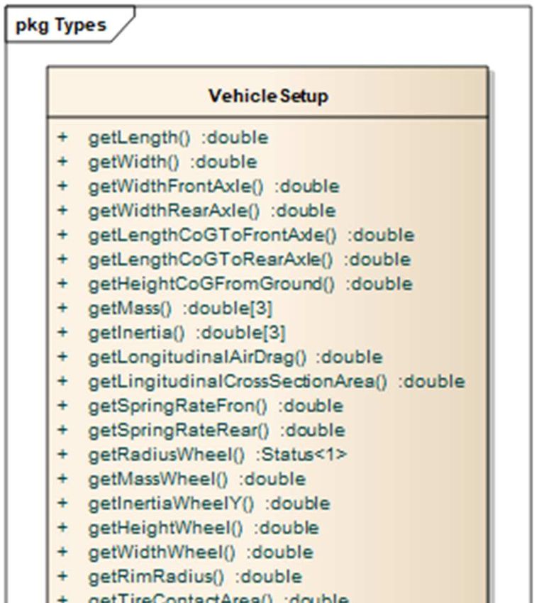
6.2.1. RADAR................................................................................................................................ 30
6.2.2. Camera .............................................................................................................................. 31
6.2.3. LiDAR ................................................................................................................................. 32
6.2.4. Vehicle bus ........................................................................................................................ 32
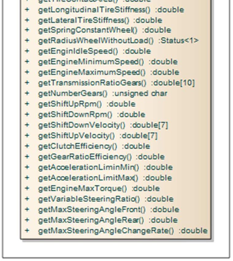
6.2.5. Vehicle Abstraction ........................................................................................................... 33
6.2.5.1. Detailed Specification ................................................................................................ 35
6.2.6. Ultrasonic .......................................................................................................................... 38
6.2.7. Map.................................................................................................................................... 38
6.2.7.1. Simple Road Graph .................................................................................................... 38
6.2.7.2. Semantic High-Accuracy Topographic Map............................................................... 39
6.2.8. V2X..................................................................................................................................... 40
6.2.8.1. V2X messages ............................................................................................................ 40
6.2.7.2. V2X data input/output .............................................................................................. 43
7. Fusion layer ............................................................................................................................... 44
8. Environment model ................................................................................................................... 44
8.1. Timing concept ...................................................................................................................... 44
8.2. Map data ............................................................................................................................... 44
8.2.1. Road graph ........................................................................................................................ 45
8.2.2. Semantic high-accurate topographic map ........................................................................ 46
8.3. Static environment model ..................................................................................................... 47
8.3.1. Freespace........................................................................................................................... 47
8.3.2. Obstacles ........................................................................................................................... 49
8.3.3. Static objects ..................................................................................................................... 50
8.3.4. Occupancy grid map .......................................................................................................... 50
8.4. Dynamic environment model ................................................................................................ 51
8.4.1. Dynamic objects ................................................................................................................ 51
8.5. Vehicle status ........................................................................................................................ 52
8.5.1. Ego motion ........................................................................................................................ 52
8.5.2. Pose ................................................................................................................................... 52
Appendix................................................................................................................................................ 52
Authors .............................................................................................................................................. 52
License ............................................................................................................................................... 53
References ......................................................................................................................................... 53
Interface Specification – Open Fusion Platform (OFP) 2 / 53
Published under Creative Commons BY-ND 4.0 License
Part 1: Basic Specifications

1. Overview
This document is created as a deliverable of the project Open
Fusion Platform [OFP], which is publicly funded by the Federal
Ministry of Education and Research (BMBF). Within the OFP
Project the Partners are developing a near series fusion platform
with open interfaces as an enabler for high- and fully automated
vehicles. By the disclosure of the interface description we want to
enable other companies, institutes or universities to easily
integrate their own products or prototypes in the OFP and
therefore accelerate the development of the new automated driving technologies. The OFP will be a
generic platform for automated driving functions, but will show the capabilities at the end of the
project by implementing the following main use case:

“An e-car autonomously parks and positions itself directly on top off a parking space with a wireless
charging plate (valet parking). After the car is fully charged, it drives itself to a normal parking space
without a charging plate.”

The following 10 main partners are working on the OFP project:

together with the 2 associated partners:

    1.1.Target of document
This document describes the IN- and OUTPUT Interfaces of the Open Fusion Platform, including many
details that are needed to incorporate new sensors or to use the fusion model for further
functionalities. The document starts with the standards used, the internal communication concept of
the OFP and then details Input and Output Interfaces of the OFP. Furthermore, Data Types, Timing
concept and Vehicle Status are addressed within this document.

The document is not complete nor will it be, as this topic is very complex. This document shall give
insights into the OFP to other interested parties, and is a starting point to use the OFP for their own

Interface Specification – Open Fusion Platform (OFP)                                   3 / 53
Published under Creative Commons BY-ND 4.0 License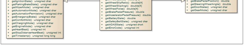
products or prototypes. Through an initial Workshop and more discussions with interested parties,
this document will grow and hopefully become a useful tool for introducing the open fusion platform
to the world. Finally, this document shall become a starting point for standardizing the interfaces of
such fusion platforms for automated driving cars.

The OFP project welcomes all types of collaboration, may it be input to this document or hands on
work implementing new prototypes with the open fusion platform. If you like to collaborate, please
get in contact with the coordinator of the OFP project, e.g. via eMail: kontakt@ofp-projekt.de

    1.2.Functional description
The OFP system architecture is formed by a number of functional layers. The reason behind this
architectural decision is the easy replacement of layers, their refinement or reworks without
influencing higher and not directly connected components. E.g., if a specified hardware component
camera will be replaced by a model with another specification (change of pixel resolution etc.), the
immediately connected layer could be influenced either due to interface changes or by necessary
adaptations of components. Higher layers are not influenced and remain stable in terms of interface
and provided functionality.

                                   Figure 1 Overview Functional Layering

Figure 1 shows the functional layering used: Hardware and software components are clustered inside
the identified layers. The Sensor Layer includes typical sensors (e.g. hardware Cameras), surrounding
peripheral units (e.g. hardware V2X module), and virtual sensors (e.g. software Map Data) as well.
These components are typically not part of the core system but deliver necessary input data for the
core system´s functionality.

The provided signals or pre-processed information (signal -> data -> information) are requested by
software components clustered in the Perception Layer. The perceptual software components are

Interface Specification – Open Fusion Platform (OFP)                               4 / 53
Published under Creative Commons BY-ND 4.0 License
specialized in the recognition (detection) of features on the provided data / information of the (real /
virtual) sensors. The low level validations (confirmations) and trackings are further main
functionalities associated to the Perception Layer. The layer components are highly sensor
dependent and are specialized for working on a suitable sensor data.

The fusion layer aggregates useful information provided by the perception layer and delivers
combined and interpreted information. Gathered information from various sensors form the new
high-level information, that provide validated and enriched information that can be estimated by the
attached sensors.

The Environment Model provides a consolidated view of the collected, processed, interpreted and
validated information. The information from all sensors are aggregated and stored in one of the high-
 class AbstractionLayer_Tegra_Sw

     Application

                                                                                  (from Software)

     Env ironment model

                                                                                  (from Software)

     Fusion

                                                                                  (from Software)

     Perception

                                                                                 (from Software)
                                                                                                          Fusion Framew ork
     RTE

                                          (from AUTOSAR)

                    pkg BSW_Tegra

                          Serv iceLayer                            ComplexDriv ers

                             + E2E
                             + TimE

                          ECU_AbstLayer
                                                                                                                                             (from Software)

                                                                                                          GENIVI

                          MCAL
                                                                                                                              (from Fusion Framework)

     OS

                                                                                  (from Software)
     Hardw are_Hw Pkg

                                                                            (from HardwareArchitecture)

                                                           Figure 2 Layering Model Performance Part

level models (static/dynamic environment, vehicle state).

The Application Layer components consume the high-level information from the Environment Model.
The analysis of the situation and the planning of further action are carried out by these applications

Interface Specification – Open Fusion Platform (OFP)                                                                                                           5 / 53
Published under Creative Commons BY-ND 4.0 License
(high-level components). The output from this layer is either used as feedback by the lower layers
(especially perception and fusion layer components) or provided to the system’s environment as
illustrated on the Actors Layer.

The interfaces between layers shall remain stable in case of methods (names and behaviours) and
exchanged data (signature and semantic of data). With fulfilling the defined contract (interface
specification) a change of components without side effects is possible.

To address the performance and the safety aspects of the subsystems two layering models are
applied. Figure 2 illustrates the pure layering for the performance architecture; Figure 3 illustrates
the layering for the safety architecture. Both layer concepts are used within the system under
development. The models have the same basic concept.

In both charts, only the main layers are presented in order to simplify the illustration.
                    class AbstractionLayer_Aurix_Sw

                           SWC

                                                                            (from AUTOSAR)

                           RTE

                                                                            (from AUTOSAR)

                        pkg BSW_Aurix

                          SafetyOS                     Serv iceLayer                                 ComplexDriv ers

                                                          + E2E
                                                          + TimE

                                                       ECU_AbstLayer

                                                       MCAL

                           Hardw are_Hw Pkg

                                                                       (from HardwareArchitecture)

                                                      Figure 3 Layering Model Safety Part

All illustrated layers and functionalities in Figure 2 and Figure 3 and are necessary for the main
functionality of the OFP. These components are deployed on the performance processors /
infrastructure of the system (i.e. Tegra X2).

To realize the necessary safety functionality – to ensure the hazardless behaviour – of the system,
the illustrated layers in Figure 3 Layering Model Safety Part are necessary. The deployment of the
safety functionality (low-level and high-level as well) are on a dedicated Safety processor (i.e. Aurix).

Interface Specification – Open Fusion Platform (OFP)                                                                   6 / 53
Published under Creative Commons BY-ND 4.0 License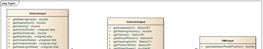
1.3.Related Works
For hardware interfaces (e.g. CAN, LVDS, …) and basic Software (e.g. AUTOSAR Adaptive) standards
are available for many years now and widely applied in automotive series products. This is not the
case for automated driving specific problems. A few initiatives, like OpenDrive [OD], already started a
few years ago, but for many issues regarding sensor fusion and environmental modelling, no
standards are available yet.

Within the first year of the OFP Project (2016) a few new initiatives went public, like the Open
Robinos white paper [OR] from Elektrobit, the Open Platform initiative [OP] from BMW, Mobileye
and Intel and the adaptive AUTOSAR [AA] enhancement.

Open Robinos is an open specification for a functional software architecture with well-defined
interfaces, software modules and control mechanism (now merging into the SOFAM initiative:
Standardized, open framework for autonomous mobility). Its aim is to invite partners, customers and
tier 1 suppliers to create a reference platform for automated driving.

Where possible and meaningful, we try to incorporate other standards and will cite the standards
within this document. The OFP interface specification will hopefully evolve over time and will only
describe those parts, which are not defined within other standardization efforts. If you think,
something is missing in this document please contact the main author.

Version 1.0 of this OFP Interface Specification was an integral input to the new ISO Specification
proposal: ISO 23150 “Data communication between sensors and data fusion unit for automated
driving functions”. [ISO23150] The OFP project takes part in the new ISO process and will make sure,
that the Open Fusion Platform will support the newly defined standards of ISO 23150.

2. Standards
    2.1.Time synchronization (PTP)
To ensure the synchronization of the fusion model data, the system needs to have a synchronized
time basis. This is achieved with a Time Synchronization between the involved ECUs based on the
IEEE 802.1AS (gPTP).

The system can be the timing master in the complete setup which requires a direct connection to a
GPS sensor with a PPS-signal for timing synchronization. A second solution setup can use an external
timing master which synchronizes all slaves via gPTP.

The timing master is the Aurix Safety-ECU on the DrivePX2 board which receives information from a
GPS receiver and the PPS (pulse-per-second) to ensure the correct time basis.

                    Standard                               Description
           IEEE 802.1AS                  Timing and Synchronization for Time-Sensitive
                                         Applications (gPTP)
                                       Table 1 - TimeSync Standard

Interface Specification – Open Fusion Platform (OFP)                               7 / 53
Published under Creative Commons BY-ND 4.0 License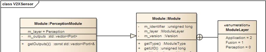
2.2.Coordinate systems
The GPS device that will be used has to deliver coordinates in WGS84 format. Starting from this
interpreted signal information the coordinates will be calculated to UTM coordinates.

The applied world reference system is Universal Transverse Mercator (UTM) coordinate system
[UTM]. This 2-dimensional Cartesian coordinate system is a horizontal position representation, the
location is independently from the vertical position. This representation realized with several maps
can be simplified for our project because a very small part of the real-world is used and the targeted
inaccuracy is obsolete.

The UTM coordinates can be transformed into common other coordinate systems.

The car reference system (Fahrzeugreferenzsystem, see Figure 4) is a 3D Cartesian coordinate system
that defines the vehicle’s dimension (inner coordinate system, body frame). The origin of the right-
hand oriented coordinate system is a defined and calibrated point inside the car’s dimension
(typically the middle of the front axis). The positive x-dimension is pointing forward seen from
driver’s perspective, the clockwise rotation is specified as positive roll angle. The positive y-
dimension is pointing to the left side from driver’s perspective, the clockwise rotation is specified as
positive pitch angle. The positive z-dimension is pointing upwards from driver’s perspective, the
clockwise rotation is specified as positive yaw angle

The used car reference system is specified in the norm ISO 8855.

                                       Figure 4 Car Reference System

Between the various coordinates system, a transformation is necessary (Figure 5). For details please
see the description in [ISO8855].

                                    Figure 5 Coordinate Transformation

Interface Specification – Open Fusion Platform (OFP)                                8 / 53
Published under Creative Commons BY-ND 4.0 License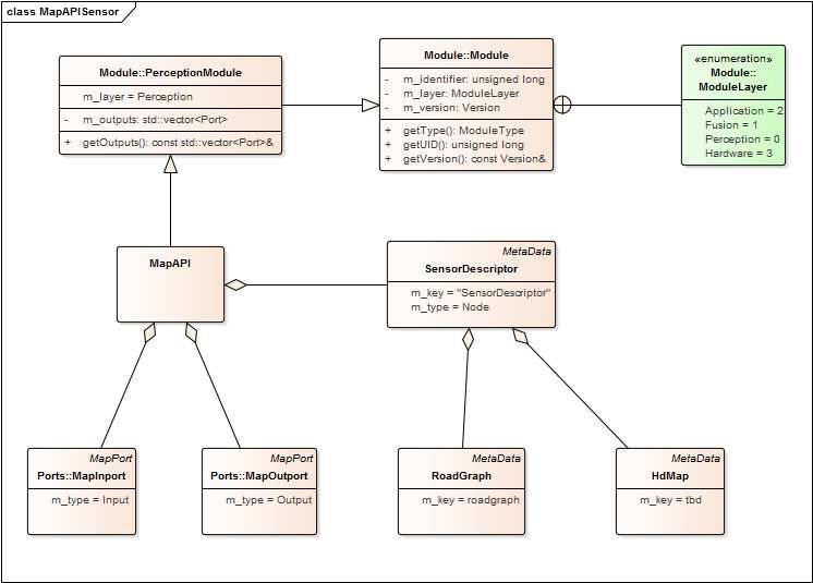
2.3. V2X communication (ITS-G5)
    The wireless communication between cooperative vehicles or vehicles and the infrastructure is
    achieved by employing the European ITS-G5 standard [ET11]. The standard is based on the IEEE
    802.11p standard, which supports robust wireless ad-hoc communications of fast moving
    stations in the 5,9 GHz frequency band.

                     Standard                                  Description
            ETSI ITS-G5                     ETSI ITS-G5 standard is based on the IEEE
                                            802.11p standard1 supporting V2X
                                            communications in a wireless ad-hoc network to
                                            be used at the 5,9 GHz frequency band allocated
                                            in Europe
                                     Table 2: V2X communication standard

    2.4.Safety
The EB tresos Functional Safety products running on the NVIDIA Drive PX2 are based on the
AUTOSAR standard and meet the ISO 26262 requirements up to automotive safety integrity level D
(ASIL D). Additionally these products are conform to the IEC 61508 standard for non-automotive use.
The products used in the OFP System are:

    •   EB tresos Safety OS

        Data protection: To provide a safe execution environment for safety-critical functions, the EB
        tresos Safety OS incorporates proven concepts such as Microkernel and System Calls from
        the aerospace and industrial markets. The result is a robust and protected Safety Operating
        System (OS) compatible with the latest AUTOSAR standard. The OS is independently certified
        for use in ASIL D applications such as electrical power steering, as well as SIL 3 use in
        nonautomotive projects.

    •   EB tresos Safety RTE

        Data protection: The EB tresos Safety RTE takes care of the safe handling of RTE services
        between software in different partitions.

    •   EB tresos Safety TimE Protection

        Execution protection: EB tresos Safety TimE Protection is a software module that enables the
        timing and execution supervision of safety-related applications. Thus, it provides freedom
        from the interference of safety-related software modules with regard to time and execution.
        EB tresos Safety TimE Protection is independently certified for use in ASIL D applications such
        as electrical power steering, as well as SIL 3 use in non-automotive projects.

1
 The IEEE 802.11p amendment is part of the active IEEE 802.11-2016 standard meanwhile, but still used for
better distinction to other standards.

Interface Specification – Open Fusion Platform (OFP)                                    9 / 53
Published under Creative Commons BY-ND 4.0 License
• EB tresos Safety E2E Protection
Communication protection: EB tresos Safety E2E Protection is a set of modules that supports
the transmission of safety-related data between ECUs. It consists of an end-to-end
communication protection library and an end-to-end protection wrapper for integration into
an AUTOSAR basic software stack.
Standard Description
ISO 26262 ISO 26262 is an international standard for functional safety of electrical
and/or electronic systems in production automobiles defined by the
International Organization for Standardization (ISO) in 2011
IEC 61508 IEC 61508 is an international standard intended to be a basic functional
safety standard applicable to all kinds of industry
Table 3 – Reference Safety Standards
2.4.1. Safety manager
To fulfill the safety requirements of autonomous driving systems the safety manager covers the
following tasks:
• Program-flow Monitoring
• Plausibility checks
• Hardware Monitoring
• Deriving safety and error strategy
Program-Flow-Monitoring
The Program-Flow-Monitoring supervises the execution-time and execution-sequence of the
architecture. Therefore checkpoints in the software will be supervised.
Name Data Type Unit Description
Checkpoint ID int Checkpoint ID to
distinguish between
different checkpoints.
Report bool Reports the passing of
the Checkpoint
Timestamp int, int ms, us Timestamp of
checkpoint passing
Table 4 – Program Flow Monitoring Interfaces
Plausibility check
A standard plausibility check is the evaluation of data thresholds and timing conditions. Next to such
easy implementations, there are further interpretation steps implemented in order to evaluate greater
and more complex parts of the architecture. As an example the result of a path planning based on a
grid based sensor data fusion can be checked against a second approach of sensor data fusion in order
to ensure that the first computation chain is working correctly.
Interface Specification – Open Fusion Platform (OFP) 10 / 53
Published under Creative Commons BY-ND 4.0 LicenseThe result of such safety and error finding driven evaluation is a list of system states:
Name Data Type Unit Description
Checkpoint ID int Checkpoint ID to
distinguish between
different checkpoints
Check result bool[] List of results for every
checked state.
Timestamp int, int ms, us Timestamp of
checkpoint
Table 5 – Plausibility check interfaces
Hardware monitoring
To monitor the status of the Hardware, there are two possible mechanisms:
• BIST - Built-in self-test
A Built-in self-test (BIST) is a built-in mechanism that allows the ECU to perform several hardware
tests.
• Question and Answer
The Safety ECU in the heterogenous System used in OFP is asking predefined questions to the
performance ECU as a challenge and response system. With this method several hardware based
computing mechanisms at the performance ECU can be tested.
The result of these tests is a list of system states.
Name Data Type Unit Description
Checkpoint ID int Checkpoint ID to
distinguish between
different checkpoints
Check result bool[] List of results for every
checked state.
Timestamp int, int ms, ys Timestamp of
checkpoint
Table 6 – Hardware monitoring interfaces
Deriving safety and error strategies
The list of check results is used to decide whether a specific behaviour can be activated due to its
activation prerequisites or – if the behaviour is already active – what fail operational mechanism shall
be activated and what information shall be stored for later error handlings.
2.4.2. AUTOSAR und AUTOSAR Adaptive
The Infineon Aurix TC297 “Safety ECU” on the NVIDIA DrivePX 2 which is used in the OFP System is
running a EB tresos AutoCore. The EB tresos AutoCore is the implementation of AUTOSAR-compliant
basic software for automotive electronic control units (ECUs). The EB AutoCore is based on AUTOSAR
4.x and includes support for 3.x releases. Therefore, the Software running on the Safety ECU will be
conformant to the AUTOSAR Standard.
Interface Specification – Open Fusion Platform (OFP) 11 / 53
Published under Creative Commons BY-ND 4.0 LicenseOn the Nvidia Tegra Processor “Performance ECU” on the NVIDIA DrivePX2 runs EB corbos on Linux.
EB corbos is an implementation of the AUTOSAR Adaptive specification. In comparison to the
AUTOSAR Classic Platform the AUTOSAR Runtime Environment for the Adaptive Platform dynamically
links services and clients during runtime.
Standard Description
AUTOSAR 3.x, AUTOSAR (AUTomotive Open System ARchitecture) is a worldwide
AUTOSAR 4.x development partnership of automotive interested parties founded
AUTOSAR Adaptive in 2003
Table 7 – AUTOSAR Standard
2.5.SI
The base units of the International System used within the projects are listed in the Table 8.
Base Quantity SI-Base Unit
Name Symbol Name Symbol
length l metre m
mass m kilogram kg
time, duration t second s
electric currency I, i Ampere A
thermodynamic temperature T Kelvin K
Table 8 – SI Base Units
Additionally to the base units, coherent derived units are used. Some examples are given in Table 9.
Derived quantity SI coherent derived unit
Name Symbol Name Symbol
speed, velocity v metre per second m/s
acceleration a metre per second squared m/s2
Table 9 – Examples of coherent derived units in the SI expressed in terms of base units
Certain coherent derived units having also own special names and symbols as shown in Table 10.
Derived quantity Name Symbol Expressed in Expressed in
terms of terms of SI base
other SI units units
plane angle radian rad 1 m/m
frequency hertz Hz s−1
force newton N m kg s−2
power, radiant flux watt W J/s m2 kg s−3
electric potential difference, volt V W/A m2 kg s−3 A−1
electromotive force
o
Celsius temperature degree Celsius C K
Table 10 – Coherent derived units in the SI with special names and symbols
For further reading please see [SI06].
Interface Specification – Open Fusion Platform (OFP) 12 / 53
Published under Creative Commons BY-ND 4.0 License3. Communication Concept
The communication concept is split-up in two strategies (see Figure 6): data-driven communication
and timing-driven communication. Starting from the lowest sensor layer, data / information is
provided to the consumer immediately after gathering. This data driven communication will be
performed through all layers and their components till the Environment Model. The environment
model fulfils the concept of the blackboard pattern.
Following from the Environment Model to Application Layer and subsequently to the Actors Layer a
timing-driven communication is realized. Within a scheduled task management data is provided to
the consumers. Depending on the consumers’ needs (e.g. bus communication, brake activation)
various time slices (e.g. 50, 100, 250 ms) can be realized.
The dataflow inside the application and actuator layer can also follow the data-driven
communication concept, but to support the deployment on these two layers on dedicated ECUs, a
timing driven communication is required.
Figure 6 Communication concept between perception/fusion and application
4. Data types – Generic
The OFP uses generic data types to enable standardized communication between all layers and
components inside these layers. All modules in the OFP have to support the generic data types if they
want to use and provide to 3rd party components.
The following classes are modelled in the system architecture, realized as a software architecture
model.
Interface Specification – Open Fusion Platform (OFP) 13 / 53
Published under Creative Commons BY-ND 4.0 License4.1.Status
pkg Types
dim : int = 3
«enumeration»
row s : int = 3
CoordinateSystem Status cols : int = 3
Sensor = 0 - m_coordinateSystem :CoordinateSystem Matrix
Car = 1 - m_covariance :Matrix
LocalReferenced = 2 - m_matrix :double[rows*cols]
- m_status :double[dim]
GlobalReferenced = 3 + operator()(int, int) :double
+ getCovariance() :const Matrix&
+ getStatus(int) :double
Figure 7 – Aggregate Class Status
The coordinate system defines how to interpret the status information.
A sensor coordinate system is defined by the direct measurements of the sensor, the Car coordinate
system is defined as a Cartesian vehicle coordinate system.
The local referenced system is a Cartesian coordinate system which is not related to the GPS
positions. The global referenced system is defined in UTM coordinates.
The aggregated class Status realizes the following interface functions:
Name of Function Description
getStatus Get the status for a specific axis.
getCovariance Get the covariance matrix.
Table 11 – Description Functions Class Status
4.2.Primitives
The OFP defines some primitives known from computer graphics to describe abstract data structures.
A polygon is defines as a closed set of lines where the start of the first line segment is equal to the
end point of the last segment.
pkg Types
Line
Polygon
- m_start :Status
- m_segments :std::vector - m_end :Status
1 *
+ getSegments() :const std::vector& + getStart() :const Status&
+ getEnd() :const Status&
Figure 8 Aggregate Class Polygon and Line
Line Description
Start The line’s start point
End The end of the line
Table 12 – Description of Line
Interface Specification – Open Fusion Platform (OFP) 14 / 53
Published under Creative Commons BY-ND 4.0 LicensePolygon Description
Segments All line segments of the polygon
Table 13 – Description of Polygon
4.3.Objects
The aggregated class Object realizes the following interface functions:
Name of Function Description
getCenter Get the center data from Status.
getClass Get the object class type.
getSize Get the size from Status.
getType Get the object type.
transform Transforms the object into another coordinate
system based on the given calibration
information.
Table 14 – Description Functions Class Object
The classes ObjectType and ObjectClass realizing the enumeration types that are used by the class
Object.
4.4.Ego Motion
pkg Types
Egomotion
+ getRotationRate(CoordinateAxis) :double
+ getVelocity(CoordinateAxis) :double
+ transform(Calibration&) :bool
Figure 9 – Class Egomotion
The class Egomotion realizes the following interface functions:
Name of Function Description
getRotationRate Get the rotation rate for a given axis.
getVelocity Get the velocity for a given coordinate axis.
transform Transforms the egomotion into another
Coordinate system based on a given calibration.
Table 15 – Description Functions Class Egomotion
Interface Specification – Open Fusion Platform (OFP) 15 / 53
Published under Creative Commons BY-ND 4.0 License4.5.Pose
pkg Types
Pose
+ getOrientation() :const Status&
+ getPosition() :const Status&
+ transform(Calibration&) :bool
Figure 10 – Class Pose
The class Pose realizes the following interface functions:
Name of Function Description
getOrientation Get the orientation from Status.
getPosition Get the position from Status.
transform Transforms the pose into another coordinate
system based on a given calibration.
Table 16 – Description Functions Class Pose
4.6.Image
pkg Types
Image
+ getImage() :const Pixel& Pixel
+ getImageArea(uint8, uint8, uint8, uint8) :Pixel&
+ transform(Calibration&) :bool
1 m
Figure 11 –Class Image
The class Image realizes the following interface functions:
Name of Function Description
getImage Get the whole image.
getImageArea Get the selected area of the image.
transform Rectifies the image based on a defined
calibration.
Table 17 – Description Functions Class Image
Interface Specification – Open Fusion Platform (OFP) 16 / 53
Published under Creative Commons BY-ND 4.0 License5. Module Manifest
The module manifest describes the software components in a running OFP environment.
A module can either be a virtual sensor in the perception layer which abstracts an existing sensor and
provides the measured information in the standardized format. Or the module is a fusion component
in the fusion layer or the module is a function component in the application layer which is reliable for
the automated driving use cases. The dependencies between these components are known during
the startup phase and the safety-ECU watches for the correct execution of active components.
The module manifest is defined as a description of identifiers, inputs, outputs and which layer
corresponds to the module. A module can be used by various use cases and a use case is related to
safety relevant constraints like maximum speed.
The module manifest can use the meta-data blocks to describe special features, constraints, use-
cases or proprietary information. The safety ECU and the framework on the performance ECU can
identify which modules are relevant for which use cases and can enable and disable modules.
pkg Module
Module
«enumeration»
- m_layer :ModuleLayer
ModuleLayer
- m_identifier :unsigned long
- m_metaData :std::vector Perception = 0
- m_version :Version Fusion = 1
Application = 2
+ getType() :ModuleType
+ getUID() :unsigned long
+ getMetaData() :const std::vector&
+ getVersion() :const Version&
+ getUseCases() :const std::vector&
MetaData
- m_key :std::string «enumerati...
- m_type :MetaDataT ype MetaDataType
- m_children :std::vector
Undefined = 0
+ getKey() :const std::string& Node = 1
+ getType() :MetaDataType Entry = 2
+ findChild(std::string&) :MetaData*
+ getParent() :MetaData*
Figure 12 – Module manifest
Interface Specification – Open Fusion Platform (OFP) 17 / 53
Published under Creative Commons BY-ND 4.0 Licensepkg Module
«enumeration» MetaData
MetaDataEntryType «enumerati...
- m_key :std::string
MetaDataEntryBase - m_type :MetaDataType MetaDataType
Other = 0
Boolean = 1 - m_children :std::vector
+ getValueType() :MetaDataEntryType Undefined = 0
Int = 2 + getKey() :const std::string& Node = 1
Float = 3 + getType() :MetaDataType Entry = 2
String = 4 + findChild(std::string&) :MetaData*
+ getParent() :MetaData*
T : typename
MetaDataEntry
- m_value :T
+ getValue() :const T&
< T->bool > < T->int > < T->float > < T->std::string >
MetaDataEntryBoolean MetaDataEntryInt MetaDataEntryFloat MetaDataEntryString
Figure 13 – Meta data blocks
The meta-data block is a tree-based structure which can contain information about the module. It is
possible to store global information with use of standard data formats or proprietary information
which can only be used by specific modules.
Every software layer contains special modules which are identified by the ModuleType. Modules in
the sensor layer convert proprietary data into the standard OFP data types and send them to the
fusion or application layer, the fusion layer modules consume data from the perception layer or
other fusion modules. The application layer modules consume data from the underlying layers and
do not provide data for other OFP components.
Interface Specification – Open Fusion Platform (OFP) 18 / 53
Published under Creative Commons BY-ND 4.0 Licensepkg Module
Module
«enumeration»
- m_layer :ModuleLayer
ModuleLayer
- m_identifier :unsigned long
- m_metaData :std::vector Perception = 0
- m_version :Version Fusion = 1
Application = 2
+ getT ype() :ModuleType
+ getUID() :unsigned long
+ getMetaData() :const std::vector&
+ getVersion() :const Version&
+ getUseCases() :const std::vector&
PerceptionModule FusionModule ApplicationModule
- m_outputs :std::vector - m_inputs :std::vector - m_inputs :std::vector
- m_outputs :std::vector
+ getOutputs() :const std::vector& + getInputs() :const std::vector&
+ getOutputs() :const std::vector&
+ getInputs() :const std::vector&
Port
- m_type :PortType
- m_component :Component «enumerati...
- m_dataType :DataType = Unknown PortType
- m_metaData :std::vector
Input = 0
+ getPortType() :PortType Output = 1
+ getComponent() :Module
+ getDataType() :DataType
+ getMetaData() :const std::vector&
Figure 14 – Layer-related module manifests
The modules have input and output ports to read and provide data in form of standardized OFP
types. Input ports read data and output ports provide data. The meta-data blocks describe provided
data or the requirements.
pkg Module
Port MetaData
- m_type :PortT ype - m_key :std::string «enumerati...
«enumerati... - m_component :Component MetaDataType
- m_type :MetaDataType
PortType - m_dataType :DataType - m_children :std::vector
- m_metaData :std::vector Undefined = 0
Input = 0 + getKey() :const std::string& Node = 1
Output = 1 + getPortType() :PortType + getT ype() :MetaDataType Entry = 2
+ getComponent() :Module + findChild(std::string&) :MetaData*
+ getDataT ype() :DataType + getParent() :MetaData*
+ getMetaData() :const std::vector&
Figure 15 Port definition with meta-data-blocks
Interface Specification – Open Fusion Platform (OFP) 19 / 53
Published under Creative Commons BY-ND 4.0 LicensePart 2: Perception Layer
6. Perception Layer
The perception layer contains all single-sensor-algorithms and provides converter modules to convert
from the proprietary sensor interfaces to the standardized generic and sensor specific data
structures. A fusion of a single sensor with an ego-motion is defined as a perception layer.
6.1.Sensor description
The OFP supports two kinds of sensor systems. The first system is a single sensor which is described
by its type, data and built-in position. The second system type can be a multi-sensor system which
describes multiple sensors as one single sensor, but the integrated single sensors are defined as
normal sensors which can be requested by other modules.
A multi-sensor system (i.e. all ultrasonic sensors) collects the measurements from all connected
single sensors and provides all measured data in one measurement list (data-types have to be
equivalent).
6.1.1. Sensor manifest
6.1.1.1. Sensor manifest – Camera
The Camera sensor is responsible for the Image interfaces. The sensor consists of two parts – the
mechanical optic part and the mechanical / electrical imager part. Both parts are combined by
construction.
The optical part is specified by vertical and horizontal opening angles. Further specifying details like
distortion coefficients are not under further investigation. The to be used output will be processed
from the imager’s captured photons, to charged electrical capacities, presented as electrical signals
and transformed into information (i.e. interpreted data). The imager is defined by the width
(horizontal dimension), the height (vertical dimension), the pattern of the imager (i.e. RGB, RCCC),
and the bit resolution of charged capacities manifested by the format (i.e. bits per picture element,
e.g. 12 bit).
The provided information is stored in the meta-data block of the output port.
Interface Specification – Open Fusion Platform (OFP) 20 / 53
Published under Creative Commons BY-ND 4.0 Licenseclass CameraSensor
«enumeration»
Module::Module
ModuleLayer
Module::PerceptionModule - m_identifier :unsigned long
ObjectListPort
CameraSensor Application = 2
Ports:: m_layer = Perception - m_layer :ModuleLayer
Fusion = 1
Obj ectListOutput - m_version :Version
0..1 1 - m_outputs :std::vector Perception = 0
m_type = Output + getType() :ModuleType
+ getOutputs() :const std::vector& + getUID() :unsigned long
1 + getVersion() :const Version& (from Module)
ImagePort
1..*
Ports::ImageOutport
m_type = Output
1
1
SensorDescriptor Ports::ImageDescriptor
m_key = "SensorDescriptor" m_key = "ImageDescriptor"
m_type = Node m_type = Node
1
1 1 1 1 1 1
BlindnessLev el
1
m_key = "BlindnessLevel"
1 1 1 1 1 1
Pattern OpeningAngleVertical OpeningAngleHorizontal Ports:: Ports:: Ports::
ImageDescriptorFormat ImageDescriptorHeight ImageDescriptorWidth
m_key = "Pattern" m_key = "OpeningAngleVertical" m_key = "OpeningAngleHorizontal"
m_key = "Format" m_key = "Height" m_key = "Width"
Figure 16 – Sensor manifest Camera
Kind of Information Description
Sensor Description Specification of module and definition of
module type (entry).
Width Description of image width.
Height Description of image height.
Bits per Pixel Description of used bits per pixel (e.g. 12 bit).
Characteristic Description of sensor’s characteristic.
Horizontal Opening Description of sensor’s horizontal opening
Angle angle.
Vertical Opening Angle Description of sensor’s vertical opening angle.
Pattern Description of pattern (e.g. RGB).
Blindness level The sensor’s blindness level
Table 18 – Camera sensor description
6.1.1.2. Sensor manifest – RADAR
The Radar sends electromagnetic waves and receives echoes from reflecting objects in the
environment. Basic information about the radar properties e.g. base frequency and
horizontal/vertical opening angle are comprised within the sensor manifest radar (see Table 19).
Furthermore, the radar delivers in regular cycles metadata about the currently used modulation
scheme and optional information about the sensor state (see Table 19).
Finally, the radar delivers the attributes range, radial speed, angle of arrival, and optional
Information for the quality of every recognized reflection within the target list (also see Section
6.2.1 RADAR).
Interface Specification – Open Fusion Platform (OFP) 21 / 53
Published under Creative Commons BY-ND 4.0 Licenseclass RadarSensor
«enumeration»
Module::Module
ModuleLayer
Module::PerceptionModule
RadarSensor - m_identifier :unsigned long
Application = 2
m_layer = Perception - m_layer :ModuleLayer
Fusion = 1
- m_version :Version
- m_outputs :std::vector Perception = 0
+ getType() :ModuleType
1 + getOutputs() :const std::vector& + getUID() :unsigned long
1 1 + getVersion() :const Version& (from Module)
0..* 1..*
Port RADARRawTargetListPort
Ports::Obj ectListPort Ports::
RADARRaw TargetListOutport
m_dataType = ObjectList
m_type = Output
1
SpeedResolution SensorDescriptor
m_key = "SpeedResolution" m_key = "SensorDescriptor"
1 1 m_type = Node 1
1
1 1 1
1
1 1 1 1 1 1
RangeResolution InterferenceLev el BlindnessLev el Frequency OpeningAngleVertical OpeningAngleHorizontal
m_key = "RangeResolution" m_key = "InterferenceLevel" m_key = "BlindnessLevel" m_key = "Frequency" m_key = "OpeningAngleVertical" m_key = "OpeningAngleHorizontal"
Figure 17 – Sensor manifest RADAR
Kind of Information Description
Sensor Description Specification of module and definition of
module type (entry).
Frequency Description of used base frequency.
mid frequency mid frequency of radar scan
3dB-beamwidth azimuth width of radar beam
azimuth
3dB-beamwidth elevation width of radar beam
elevation
data acquisition duaration of radar scan
duration
max range max radial detection range of sensor
Range gate length Length of the range gate
Table 19 – RADAR sensor description
6.1.1.3. Sensor manifest – LiDAR
The LiDAR sensor typically scans an area and does time of flight measurements of the reflection of a
laser impulse for a grid within the field of view. The sensor is specified by vertical and horizontal
opening angles, the maximum distance of the LiDAR beams and the resolution of a single scanned
point. The backscattering of the laser impulse is measured via highly sensitive diodes, preprocessed
and then presented as output from an ADC.
In the LiDAR sensor manifest, the field of views, the resolution and the maximal distance are defined.
Interface Specification – Open Fusion Platform (OFP) 22 / 53
Published under Creative Commons BY-ND 4.0 Licenseclass LiDARSensor
Module::Module
«enumeration»
Module::PerceptionModule
- m_identifier :unsigned long ModuleLayer
m_layer = Perception - m_layer :ModuleLayer
- m_version :Version Application = 2
- m_outputs :std::vector Fusion = 1
+ getType() :ModuleType Perception = 0
+ getOutputs() :const std::vector& + getUID() :unsigned long
+ getVersion() :const Version&
(from Module)
LiDARRawTargetListPort
LiDARSensor
Ports::
LiDARRaw TargetListOutport
1 n
m_type = Output
1
1
0..1 1
ObjectListPort
SensorDescriptor BlindnessLev el
Ports::
Obj ectListOutput m_key = "SensorDescriptor" m_key = "BlindnessLevel"
m_type = Node 1 1
m_type = Output
1 1
1 1
Range OpeningAngleHorizontal OpeningAngleVertical
m_key = "Range" m_key = "OpeningAngleHorizontal" m_key = "OpeningAngleVertical"
Figure 18 – Sensor manifest LiDAR
Kind of Information Description
Sensor Description Specification of module and definition of
module type (entry).
Max Distance Description of the maximum distance that could
theoretically achieved with the sensor.
Horizontal Opening Description of the horizontal opening angle of
Angle the LiDAR sensor.
Vertical Opening Angle Description of the vertical opening angle of the
LiDAR sensor.
Resolution Resolution of a single measurement point of the
measurement matrix.
Blindness level The blindness level of the sensor
Table 20 – LiDAR sensor description
6.1.1.4. Sensor manifest – Ultrasonic
The ultrasonic sensor can be a multi-sensor system of more than one ultrasonic sensor or as one
single ultrasonic sensor.
Interface Specification – Open Fusion Platform (OFP) 23 / 53
Published under Creative Commons BY-ND 4.0 Licenseclass UltrasonicSensor
Module::Module
«enumeration»
Module::PerceptionModule
- m_identifier :unsigned long ModuleLayer
m_layer = Perception - m_layer :ModuleLayer
- m_version :Version Application = 2
- m_outputs :std::vector Fusion = 1
+ getType() :ModuleType Perception = 0
+ getOutputs() :const std::vector& + getUID() :unsigned long
+ getVersion() :const Version&
(from Module)
USRawTargetListPort
UltrasonicSensor
Ports::
USRaw TargetListOutport
1 1
m_type = Output
1
1
SensorDescriptor
m_key = "SensorDescriptor"
m_type = Node
1 1
1
BlindnessLev el 1 Range OpeningAngleHorizontal
m_key = "BlindnessLevel" m_key = "Range" m_key = "OpeningAngleHorizontal"
Figure 19 – Sensor manifest Ultrasonic
Kind of Information Description
Sensor Description Specification of module and definition of
module type (entry).
Horizontal Opening Angle The horizontal opening angle
Vertical Opening Angle The vertical opening angle
Range The measurement range
Blindness level The blindness level of the sensor
Table 21 – Ultrasonic sensor description
The ultrasonic output port does not contain additional information per default.
class USRaw TargetListPort
Module::Port
- m_type :PortType
- m_component :Component
USRaw TargetListPort USRaw TargetListOutport
- m_dataType :DataType = Unknown
m_dataType = USRawTargetList m_type = Output
+ getPortType() :PortType
+ getComponent() :Module
+ getDataType() :DataType
Figure 20 – Ultrasonic output port
Interface Specification – Open Fusion Platform (OFP) 24 / 53
Published under Creative Commons BY-ND 4.0 License6.1.1.5. Sensor manifest – Vehicle Bus
The vehicle bus sensor is responsible for the CAN and FlexRay interfaces. The sensor provides a look-
up table to translate the messages’ and signal’s names into unique IDs which can be parsed by the
consuming modules. The look-up table is stored in the meta-data block of the output port.
class VehicleBusSensor
Module::Module
Module::PerceptionModule «enumeration»
- m_layer :ModuleLayer
ModuleLayer
m_layer = Perception - m_identifier :unsigned long
- m_version :Version Perception = 0
- m_outputs :std::vector Fusion = 1
+ getType() :ModuleType
+ getOutputs() :const std::vector& Application = 2
+ getUID() :unsigned long
+ getVersion() :const Version& (from Module)
VehicleMessagePort
VehicleBusSensor
Ports::
VehicleMessageOutport
1 1
m_type = Output
Figure 21 –Vehicle bus sensor manifest
Kind of Information Description
Sensor Description Specification of module and definition of
module type (entry).
Table 22 – Vehicle bus sensor description
The vehicle bus output port provides the meta information about the translation from message- and
signal-names to unique IDs, like DBC-files. One message can contain multiple signals and a
VehicleMessageMap describes one message. The message’s name is stored in the key and the first
entry in the list of TranslationEntries provides the mapping from the message’s name to the ID.
Interface Specification – Open Fusion Platform (OFP) 25 / 53
Published under Creative Commons BY-ND 4.0 Licenseclass VehicleMessagePort
1
Module::Port
Module::MetaData n
- m_type :PortType «enumerati...
- m_key :std::string
- m_component :Component MetaDataType
- m_type :MetaDataType
- m_dataT ype :DataT ype = Unknown
+ getKey() :const std::string& Undefined = 0
+ getPortType() :PortType 1 n Node = 1
+ getT ype() :MetaDataT ype
+ getComponent() :Module Entry = 2
+ findChild(std::string&) :MetaData*
+ getDataType() :DataType
+ getParent() :MetaData*
(from Module)
«enumeration»
MetaDataEntryType
Module::MetaDataEntryBase
Other = 0
m_type = Entry Boolean = 1
Int = 2
- m_unsigned :bool Long = 3
+ getValueType() :MetaDataEntryType Float = 4
String = 5
VehicleMessagePort
(from Module)
m_dataType = VehicleMessage T : typename
Module::MetaDataEntry
- m_value :T
+ getValue() :const T&
VehicleMessageOutport < T->unsigned long >
m_type = Output
Module::
MetaDataEntryULong
1
1
The TranslationEntry
VehicleMessageMap TranslationEntry translates the message's
name to a message ID
m_type = Entry (only one per
1 n VehicleMessageMap)
and translates the
signal's names to signal
IDs
Figure 22 – The vehicle bus output description
6.1.1.6. Sensor manifest – Vehicle-to-X (V2X)
Figure 23: Sensor manifest V2X
Interface Specification – Open Fusion Platform (OFP) 26 / 53
Published under Creative Commons BY-ND 4.0 LicenseKind of Information Description
Sensor Description Specification of module and definition of
module type (entry).
Station ID Unique ID of the V2X station with this sensor
Table 23: V2X sensor description
The information obtained by means of V2X communication with other cooperative vehicles or the
infrastructure is preprocessed in the V2X applications and the relevant data is exchanged through the
corresponding interface. There are four main categories of data, which are essential for the interface
to the fusion platform.
It is important to note that the V2X sensor not only delivers input data to the fusion platform, but also
requires input data from the fusion platform to create and disseminate V2X messages to other
cooperative vehicles or the infrastructure (see sec. 6.2.8.1).
Object information is one fundamental element:
Name Data type Description
objectID Integer Unique ID of object
class Enumeration Object class (e.g. vehicle, infrastructure, pedestrian,
unknown)
static Boolean Classification, if static or dynamic object
positionVector Record Position information in WGS84 (see Table 25)
motionVector Record Motion information (see Table 26)
dimensionVector Record Dimension information (see Table 27)
detectionTime Integer Detection time of object as UTC-timespamp in ms
Table 24: object information
Name Data type Description
latitude Float Latitude in degree
longitude Float Longitude in degree
altitude Integer Altitude in cm
Table 25: positionVector
Name Data type Description
heading Integer Heading in degree
speed Float Speed in m/s
acceleration Float Acceleration in m/s²
direction Enumeration Movement direction (forward, backward, unknown)
Table 26: motionVector
Name Data type Description
length Integer length in cm
width Integer width in cm
Table 27: dimensionVector
Another element provided by the V2X sensor is parking lot information. The data fields described in
Table 28 are related to one single lot. Hence, information about an entire parking area results in a list
of this lot information for each lot in the parking area:
Interface Specification – Open Fusion Platform (OFP) 27 / 53
Published under Creative Commons BY-ND 4.0 LicenseYou can also read