2 Electric Car Operation and Flywheel Energy
←
→
Page content transcription
If your browser does not render page correctly, please read the page content below
2 Electric Car Operation and Flywheel Energy
  Storage

Prof Dr. Andreas Daberkow, Marcus Ehlert, Dominik Kaise

Abstract: Since 2009 Heilbronn University has been investigating the specific
needs of individual and commuter traffic for electric car operation in urban-
regional areas. The plug-in battery-powered university research car has 26
lithium-based batteries, each with a capacity of 160 Ah and a voltage of 3.2 V.
From approx. 11000 Ion of test drives with measurements and recordings of state
variables like motor current or regenerative braking current it becomes clear that
the available range allows reliable operation not only in urban, but also in mixed
urban-regioual areas. However, range remains an issue so that further research
was started on additioual flywheel range-extending systems. The paper reports
first resnlts of the flywheel system investigations. With a flywheel operation
speed of 40 000 rpm basic effects of energy regeneration are investigated. Also,
first resnlts of the investigations concerning flywheel dynamics on the vehicle
dynamics are presented.

Keywords: Electro mobility, Flywheel Energy Storage, Battery Electric Vehicle
Operation

2.1     Introduction
The regioual confederation Heilbronn-Franken is typical for a large number of
mixed urban-regional districts in Germany and also in Europe, too. Typical for
the Heilbronn-Franken area close to the southwest metropolitan area of Stuttgart
is a slightly hilly landscape as seen in Figure I.
    Electro mobility in the understanding of battery-powered road vehicles pro-
motes pollution reduction and energy saving in transportation. Heilbronn Univer-
sity was supported in 2009 by the ZIP (futore investment program) program of
the Baden-Wiirttemberg state to investigate electrically powered passenger car
impacts on mixed urban-regional transportstion (initial project funding).

M. Lienkamp (Ed.), Conference on Future Automotive Technology,
DOI 10.1007/978-3-658-01141-3_2, © Springer Fachmedien Wiesbaden 2013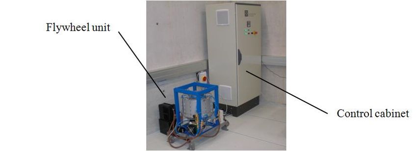
20                                                        I Energy Storage Technologies

Figure 1:       Typical landscape view of South-west regional district of Heilbroon-Frao-
                ken [I] and University Electric car during winter overnight charging

   Intense discussions with electric car manufacturers in 2009 led to the procure-
ment of a CITYSAX vehicle [2]. In close discussions with the manufacturer and
the local service partner Auto Neff Heilbronn this Chevrolet Matiz conversion
vehicle was supplemented by measurement and recording equipment. Figure 2
shows 8 of 26 traction batteries located in the space of the former engine cooling
unit. The asynchronous electric motor with a permanent power of 16 kW and a
peak power of 26 kW is adapted to the 5 -speed gearbox clutch that is adopted
from the gasoline-driven model. On top of the front traction battery unit and the
electric motor a platform holds the 220 V DC to AC charging device, the AC to
DC motor converter equipment and the 83.2 V DC to low voltage 12 V DC
converter.
   Further batteries are located in the former spare wheel compartment of the
vehicle, battery charging and overall control units are located in the inner

                               AC to DC charging device                12 V supply battery

 8 front traction batteries     Asynchronous motor conv erter

Figure 2:       Electric car and components, front car view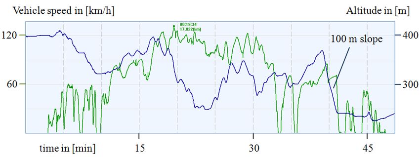
Electric Car Operation and Flywheel Energy Storage                                        21

   Vehicle speed in [km/h]                                              Altitude in [m]

 120 --l-~-'"

  60                                                                               - 300

         time in [min]       15                     30                     45

Figure 3:     Vehicle speed and GPS logging of topographic profile of electric vehicle in
              50 Ion driving cycle

compartment of the vehicle. The rear cargo volume provides space for additional
equipment like fast charging or future range-extending prototype devices.
   Now, the Heilbronn Uuiversity team has tested more than 11000 km with the
CITYSAX electric car in autumn, winter and spring conditions, see [3]. Even in
cold winter conditions of 2012 (including partially overnight parking with no
weather protection) an operation was reliable, due to the gasoline-driven parking
heater the internal compartment heating had no effects on range. It was decided
to choose a set of realistic urban-regional driving cycles divided into ranges of 5,
12, 25, 50 and 75 Ion. The 50 km driving cycle is a one-way driving scenario, the
reverse direction of 50 km is passed after recharging the car. Figure 3 shows the
topographic profile and the vehicle speed in the 50 km cycle from Stuttgart to
Heilbronn, Figure 4 shows the velocity and the power consumption from data
loggings in the reverse direction.
   It is remarkable that a peak power of 26 kW is sufficient to compete in
today's high-speed motorway traffic. Also, Figure 4 shows the energy regenera-
tion advantage by braking indicated by negative power consumption values.
   The Heilbronn University team is convinced that electric car operation in
mixed urban - regional areas is feasible for commuter traffic today. However,
range is an issue for electric car operation today and in the future. Therefore
range-extending techniques were investigated immediately and in close relation
to the test driving cycles.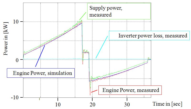
22 I Energy Storage Technologies
Vehicle speed (red, top fi gure) in [km/h] and power consumption (green, bottom) in [kW]
120 + ················· c ················· , ··········· W~.
time in [min] 20 40 60
Figure 4: Vehicle speed and power consumption in 50 Ion cycle, opposite direction
2.2 Flywheel range extending approach
Range-extending techniques for electric vehicles are in lively discussion today.
One of the first-ever series plug-in hybrid cars available today is the Chevrolet
Volt unveiled in 2007 by the General Motors Company. The Chevrolet Volt and
the similar model Opel Ampera or Vauxhall is called a plug-in hybrid electric
vehicle that can be operated as a purely battery electric vehicle. When its battery
capacity reaches a defined discharge state, its gasoline combustion piston engine
powers an electric generator to extend the vehicle's range, see e.g. [4]. Further
range-extending approaches are based on the Wankel rotary engine or on super-
capacitors. The range-extending scenario described here is based on the flywheel
energy storage system principle. Flywheel energy storage and propulsion sys-
tems have been investigated in some industrial applications, primarily for statio-
nary emergency energy supply or for the delivery of high energy rates within a
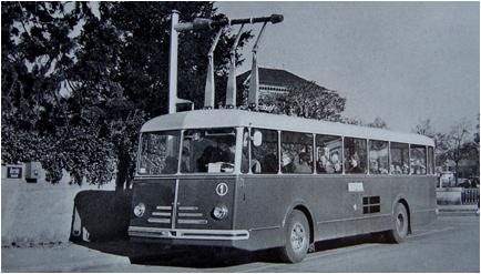
short time period. Figure 5 shows the Gyrobus as an automotive application that
was built and operated 1953 in Switzerland. Its flywheel had a weight of 1.5 tons
and revolved with a maximum speed of3000 l/min, see [5].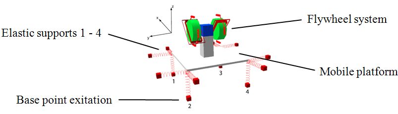
Electric Car Operation and Flywheel Energy Storage                                23

FigureS:     Gyrobus [5]

   New flywheel materials like carbon fiber and further progress in high speed
power electronics led to a renaissance of the flywheel approach. Recent deploy-
ments of flywheel storage systems are described in Porsche race technology
applications, see [6]. Here the flywheel which is connected to an electric drive
system rotates with a maximum speed of 40000 1Imin. Also the Volvo Motor
company announces an additional flywheel storage system with a maximum
speed of 60000 1Imin, see [7] and Figure 6.
   There are several advantages in a flywheel energy storage system. On the one
hand, its basically mechanical assembly allows multiple discharges and rechar-
ges that are not possible for modero lithium batteries. Also the short-term delive-
ry of high energy rates is not compatible with a long duration of battery life. On
the other hand, high speed flywheels need additional devices for the reduction of
air and bearing friction that enlarges self-discharge. Also, the installation within
a mobile platform may cause vibrations and may need appropriate suspension
devices, see [8].

Figure 6:    Porsche (left) and Volvo (right) flywheel energy stomge application des-
             criptions from [6] aod [7]
24 I Energy Storage Technologies In the scope of this research project two basic scenarios of preview range ex- tending and fast recharging are considered that differ from todsy's range-extend- ing strategies. Preview range extending In this case the Range extension via flywheel energy storage is supposed to be done before starting a car ride for which more energy is needed. For this pur- pose, the flywheel range extender is charged on demand and its energy is con- sumed at the beginning of the ride. During this phase the flywheel range exten- der saves traction battery energy. This also takes into account of the fact that the flywheel energy may be needed for trip specific compartment heating, compart- ment cooling, peak acceleration or extreme uphill slope requirements. This pre- view operation mode takes into account that nowadsys an average continuous battery electric car ride does not exceed 1-2 hours. It is designed to prevent fly- wheel power demands in the case of disadvantageous self-discharge conditions. Fast recharging In this operation mode range, extension via flywheel energy storage is supposed to be available when an unexpected recharge due to trip conditions is necessary. Here, the flywheel principle is advantageous since fast charging reduces the life- span oftoday's lithium-type batteries. A mid-term goal is an emergency recharg- ing suitable for an additional 20 min or 20 Ian electric car trip. For both cases it has to be decided if energy regeneration via braking is transformed into the flywheel or the traction battery capacity. Further flywheel energy storage applications may include emergency power supply for a vehicle's electric network balance or even for stabilizing the ride comfort. From initial discussions of the research scenarios it became clear that research activities are advantageously decoupled. One research subtopic comprises ques- tions about energy conversion between flywheel and electric motor/generator unit including power electronics devices. All results from simulations and ex- periments for this subtopic were generated in the Master study project and thesis [9]. Another important research subtopic is the dynamic interaction between the flywheel and the supporting mobile platform. All results from simulations and experiments for this subtopic were elaborated during the master study project and thesis [10] and will be explained in the next chapter.
Electric Car Operation and Flywheel Energy Storage                                       25

2.3    Flywheel and mobile platform interaction
After theoretical prestudies on flywheels, see e.g. [II] it was decided to establish
a simulation model for mobile platforms close to the University Electric Vehicle
design. Therefore, the mobile platform simulation model is provided with an in-
tegrated flywheel unit with a maximum of two revolving disks. All model setups
and simulations were performed with the computer simulation tools MATLABI
Simulink and SIMPACK. A proper validation of the simulation model and its
results was an important goal of the project. Initial validation plans for a new
smaller scale laboratory mobile flywheel design and manufacturing were dis-
cussed and abandoned due to project time and costs. Instead of this, the research
project team decided to follow the practical idea described in [10]. Here, the
mobile platform testbed is simulated by the programmable movements ofan arti-
culated industrial robot available in the Heilbronn University robot laboratory. It
allows the indication and reproduction of typical yaw and move motions to a
versatile adapter that connects with a smaller scale flywheel device. The connec-
tor itself includes a torque and force measurement unit to identify the internal
forces and torques applied during the euforced robot motion. Finally, a commer-
cial camera flywheel stabilizing device from Keynon company [12] was chosen
and mounted to the connector, see Figure 7.
   The flywheel device consists of two hinged flywheels with external power
supply and a maximum speed of20 000 lImin rotating in a helium-tight housing.
   Comprehensive work was necessary on the set-up, calibration and validation
of this approach. Since an internal design of the cardanic hinges and force
elements of the flywheel device was not documented, intensive work including
X-Ray video recordings was required to identify the flywheel device parameters

 Articulated                                                             Connector, here in
       robot                                           .."', ...."...- yaw position around
                                                                              vertical axis

                                                                               Flywheel
                                                                            stabili zation
                                                                                   device

Figure 7:      Mobile platfonn testbed with articulated robot, conoector aod flywheel
               device
26 I Energy Storage Technologies
_ _ _ _ Measurements
.::
o
Time in [sec] 4 8 12 16 20
FigureS: Vertieal torque of flywheel stabilization device during yaw motion
itself. Figure 8 shows the vertical torque from measurements and simulations
induced from a yaw movement with 24°/sec. Due to the internal elasticity of the
force aod torque sensor, all measurements were superimposed by vibrations.
After these preceeding investigations a validated simulation model was set up
in Simulink and SIMPACK aod finally ready for adaptioo aod scaling to a
mobile platform. This platform is a first approximatioo with the parameters of
the subcompact electric vehicle. The simulation model now allows variable para-
meter aod hinge design modifications aa well as different flywheel speeds, orien-
tations aod moments of inertia, see Fignre 9.
First simulations show the influence of flywheel hinging modificatioos on the
vehicle movements including stabilizing effects. Further simulation and analysis
work on the basis of this validated aod scalable simulation model is planned.
_ - -- - Flywheel system
Elastic supports 1 - 4
---~ Mobileplatfonn
••
Base point exitation - - - - ~
Figure 9: Simulation model of flywheel on mobile platformElectric Car Operation and Flywheel Energy Storage 27
2.4 Energy Dynamics
All basic work concerning the interaction between flywheel, power electronics
and the electric motor/generator unit is comprised in the research study [9]. To-
gether with the power electronics company ARADEX GmbH and the flywheel
manufacturing company Rosetta GmbH a stationary flywheel system was simu-
1ated, designed, manufactured, installed and tested, see Figure 10. All simula-
tions were done with MATLAB/Simulink.
Flywheel unit
Control cabinet
Figure 10: Stationary flywheel testbed with flywheel unit and control cabioet
The simplified laboratory flywheel prototype without carbon fibre wheel body
has a maximum speed of approx. 40 000 lImin and an energy content of70 kWs.
To reduce complexity no vacuum was generated, the energy was consumed via
electric recovery into the University electric supply network. The double-pole
synchronous electric motor/generator unit has a peak power of 15 kW.
Parameters for the moments of inertia and especially for bearing friction were
calculated and measured in close collaboration with the flywheel supplier. The
characteristic curves for friction torque modeling are determined from decelera-
tion tests. Comprehensive tests including high speed acceleration, constant speed
runs and fast deceleration show a very good compliance between simulation
model and measurements, see Figure II.
This testbed is now designed for flywheel devices with a higher energy con-
tent and higher speed. It also became clear that self-discharge is one of the main
optimization targets for flywheel energy storage systems. Based on the simula-
tions and measurements, a flywheel model with an energy content of 1.5 kWh
was simulated together with the University electric car and Heilbronn drive cycle
parameters. A theoretical drive length of 8 min including the ascending slope of28 I Energy Storage Technologies
Supply power,
measured
10 20 30 Time in [sec]
Figure 11: Flywheel power characteristics from fast acceleration and deceleration
within 35 s
Figure 3 shows that further work must be done on the fly-wheel layout and
especially on the bearing and air friction. In the next step the energy recovery
into the University electric supply network will be replaced by a controllable
resistance energy consumption.
2.5 Conclusion
From 11000 km test experience with a 26 kW powered electric car of 13 kWh
range, the Heilbronn University team is convinced that electric car operation in
mixed urban - regional areas is feasible today especially for commuter traffic.
However, range is and will be an issue for all battery electric vehicles. In this
paper, a fly-wheel range-extending approach is investigated by theoretical,
simulation and laboratory research.
Therefore, two new basic operation strategies are proposed. A ''preview range
extending" strategy consumes the precharged flywheel energy content early at
the beginning of a travel not ouly for traction but also for heating and cooling
purposes. This strategy compensates the effects of flywheel energy losses due to
friction. The "fast recharging" strategy holds if uoexpected range extensions
occur. Here, the flywheel capability of multiple fast charging without reduction
of lifetime is utilized. During further initial work, two basic research tracks forYou can also read