In-Plane Impact Dynamics Analysis of Re-Entrant Honeycomb with Variable Cross-Section
←
→
Page content transcription
If your browser does not render page correctly, please read the page content below
Computer Modeling in
                                                                                                      Tech Science Press
            Engineering & Sciences

DOI: 10.32604/cmes.2021.014828

ARTICLE

In-Plane Impact Dynamics Analysis of Re-Entrant Honeycomb
with Variable Cross-Section
Yuanxun Ou1,2 , Shilin Yan1,2 and Pin Wen1,2,*
1
    Department of Engineering Structure and Mechanics, Wuhan University of Technology, Wuhan, 430070, China
2
    Hubei Key Laboratory of Theory and Application of Advanced Materials Mechanics, Wuhan, 430070, China
*
    Corresponding Author: Pin Wen. Email: wenpin@whut.edu.cn
Received: 02 November 2020 Accepted: 11 December 2020

     ABSTRACT
     Due to the unique deformation characteristics of auxetic materials (Poisson’s ratio μ < 0), they have better shock
     resistance and energy absorption properties than traditional materials. Inspired by the concept of variable cross-
     section design, a new auxetic re-entrant honeycomb structure is designed in this study. The detailed design method
     of re-entrant honeycomb with variable cross-section (VCRH) is provided, and five VCRH structures with the
     same relative density and different cross-section change rates are proposed. The in-plane impact resistance and
     energy absorption abilities of VCRH under constant velocity are investigated by ABAQUS/EXPLICIT. The results
     show that the introduction of variable cross-section design can effectively improve the impact resistance and
     energy absorption abilities of auxetic re-entrant honeycombs. The VCRH structure has better Young’s modulus,
     plateau stress, and specific energy absorption (SEA) than traditional re-entrant honeycomb (RH). The influence
     of microstructure parameters (such as cross-section change rate α) on the dynamic impact performance of VCRH
     is also studied. Results show that, with the increase in impact velocity and α, the plateau stress and SEA of VCRH
     increase. A positive correlation is also found between the energy absorption efficiency, impact load uniformity
     and α under both medium and high impact speeds. These results can provide a reference for designing improved
     auxetic re-entrant honeycomb structures.

     KEYWORDS
     Auxetic re-entrant honeycombs; variable cross-section design; in-plane impact; finite element simulation

1 Introduction
    Different from traditional materials, auxetic materials (Poisson’s ratio μ < 0) are wider per-
pendicular to the tensile direction, and narrower perpendicular to the compression direction.
Due to their great advantages in shear resistance, indentation resistance, fracture resistance and
energy absorption properties [1–4], auxetic materials have been applied in various fields, including
sound insulation, shock absorber, sandwich panel composite core and artificial prosthesis [5–8].
Various microstructure models have been developed to enhance the mechanical properties of
auxetic materials [4]. Especially in the impact process, the dynamic response characteristics of
auxetic re-entrant honeycomb are heavily dependent on its non-uniform deformation. Moreover,

                                 This work is licensed under a Creative Commons Attribution 4.0 International License,
                                 which permits unrestricted use, distribution, and reproduction in any medium, provided the
                                 original work is properly cited.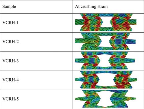
210                                                                         CMES, 2021, vol.127, no.1

the cellular structure has a great influence on the evolution of macro/micro dynamic stress [1].
Therefore, researchers are continually focused on designing better cell structure to enhance the
impact resistance and impact energy absorption abilities of auxetic material, and to ultimately
achieve better dynamic performance in line with the engineering requirements.
     Significant efforts have been made by researchers to study the relationship between the
geometric structure and mechanical properties of auxetic material. Xiao et al. [9] predicted the
crashworthiness of re-entrant auxetic honeycomb under quasi-static loads and dynamic loads of
different impact velocities by using finite element method. The results showed that different load
conditions have great influence on the load-bearing, energy absorption and deformation modes
of re-entrant auxetic honeycomb. Hu et al. [10] and Hou et al. [11] analyzed the cell structure
parameters of re-entrant auxetic honeycomb, including cell wall angle, ratio of wall thickness
to wall length, etc. Tan et al. [12] designed two levels of re-entrant auxetic honeycomb based
on hexagon substructure and equilateral triangle substructure. It was found that the designed re-
entrant auxetic honeycomb has higher energy absorption capacity. Dong et al. [13] studied the
influence of wall thickness on re-entrant auxetic honeycomb deformation mode and the effect
of negative Poisson’s ratio on crushing stress through experimental and numerical methods. They
found that there are great differences in deformation modes and energy absorption between
re-entrant auxetic honeycomb with thin-wall and thick-wall. Sun et al. [14] proposed a multi-
functional layered honeycomb structure, whose mechanical properties such as Young’s modulus
were derived based on the Euler beam theory. Lu et al. [15] designed a new honeycomb structure
with a narrow rib in the inner concave honeycomb structure. Fu et al. [16] derived the analytical
solutions of equivalent Young’s modulus and Poisson’s ratio for a new chiral three-dimensional
auxetic material by using beam theory. Li et al. [17] designed a two-dimensional multi-level con-
cave honeycomb structure, and studied its energy absorption effect under different levels by finite
element method. Hou et al. [18] improved the two-dimensional multi-level concave honeycomb
structure. Then, they used the finite element method to analyze the dynamics of the improved
honeycomb structure in order to further improve the energy absorption effect. Zhang et al. [19]
proposed a bio-inspired re-entrant arc-shaped honeycomb, and studied the influence of cellular
microstructure on its impact dynamic response characteristics. The above literature review shows
the mechanical behavior of auxetic re-entrant honeycombs has been widely studied, but most of
the previous studies assume that the cross-section of the structure remains unchanged. There are
few studies on auxetic re-entrant honeycomb with variable cross-section.
    Recently, some researchers have introduced the idea of variable cross-section, which can
improve the impact resistance and energy absorption abilities of structures. In order to improve
the crashworthiness of the front longitudinal beam (S-shaped thin-walled beam), Xu et al. [20]
designed a variable cross-section S-shaped thin-walled beam. Zhang et al. [21] proposed a kind
of multi-cell thin-walled structure with variable cross-section, and studied the influence of wall
thickness on its energy absorption abilities. Xiaofei et al. [22] proposed a new rhombic dodeca-
hedron lattice structure with variable cross section, which has better mechanical properties and
energy absorption than the original one.
     In this paper, based on the variable cross-section design concept and the traditional re-entrant
honeycomb structure, a re-entrant honeycomb with variable cross-section (VCRH) was proposed.
Different cell wall structures were designed to improve the impact resistance and energy absorption
abilities. Then, the dynamic mechanical behavior of VCRH was compared to that of traditional
re-entrant honeycomb (RH). Finally, the effects of impact velocity and cell microstructure on the
impact deformation characteristics, plateau stress and specific energy absorption (SEA) of VCRH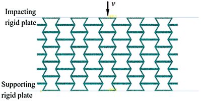
CMES, 2021, vol.127, no.1                                                                        211

were studied by numerical simulation. This study provides a new way to improve the mechanical
properties and impact resistance of cellular materials.

2 Design of Structures
     The cell structures of RH and VCRH are shown in Fig. 1. The geometric dimensions of
inclined cell wall length l, horizontal cell wall length a and inclined cell wall angle θ of the two
cell structures are consistent. In this study, l = 20 mm, a = 10 mm, and θ = 120◦ . All cell walls
of RH cells have uniform cross-section with thickness of t, while horizontal cell walls of VCRH
cells have variable cross-section. The maximum and minimum thicknesses are found at both ends
and at the middle of the horizontal cell wall, which are t1 and t2 respectively.

                            Figure 1: Unit cell structures: (a) RH, (b) VCRH

     Different from other materials, the most important characteristic of a cellular material is its
relative density. The purpose of using the relative density is to eliminate the influence of the mass
of porous structure on the mechanical properties. The relative density is defined as follows:
       ρ0
Δρ =                                                                                              (1)
       ρs
where ρ0 is the initial density and ρs is the material density of the structures. For the RH
structure, the formula for calculating the relative density is as follows:
       (2l + a)t
Δρ =                                                                                              (2)
          la sin θ2

    The VCRH cell is composed of two kinds of cell walls, including four inclined cell walls with
uniform cross-section and two horizontal cell walls with variable cross-section. The relative density
of honeycomb with variable cross-section can be given by the following formula:
       4S1 + 2S2
Δρ =                                                                                              (3)
          ab
where S1 and S2 represent the areas of inclined and horizontal cell walls:
S1 = lt                                                                                           (4)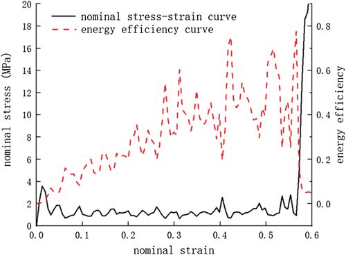
212                                                                              CMES, 2021, vol.127, no.1

                        t      t
       (t1 + t2 )(a − sinθ + tanθ )         t21
S2 =                                  −                                                                (5)
                    2                     tanθ
     In order to quantify the change in horizontal cell wall cross-section, the cross-section change
rate α is proposed:
          t2 t1 − t2
α =1−        =                                                                                         (6)
          t1    t1

     The cross-section change rate α ranges from 0 to 1. The VCRH will degenerate into RH when
α = 0. In the following research, the effective relative density Δρ remains unchanged. Notably, the
relative density is not exactly the same due to errors. Different combinations of thickness t1 and
t2 are selected to obtain the representative α. Tab. 1 lists all the cellular configurations considered.

                                  Table 1: Geometric parameters of VCRH
                             Sample               Δρ       t1     t2       α
                             VCRH-1               0.2235   1      1        0
                             VCRH-2               0.2236   1.11   0.89     0.2
                             VCRH-3               0.2238   1.25   0.75     0.4
                             VCRH-4               0.2237   1.42   0.57     0.6
                             VCRH-5               0.2241   1.65   0.33     0.8

3 Finite Element Simulation Analysis
3.1 Finite Element Model
     In order to analyze the influence of cross-section change rate α on the impact resistance and
energy absorption abilities of VCRH, ABAQUS/EXPLICIT software was used to simulate the
conventional and new-type re-entrant honeycomb structures. The finite element model of VRCH
is shown in Fig. 2 (taking VCRH-1 for example). The matrix material in the numerical simulation
is aluminum with density ρ of 2700 kg/m3 , Young’s modulus E of 69 GPa, and Poisson’s ratio ν
of 0.3 The ideal elastic-plastic model obeys Mises yield criterion, where yield stress σys is set to 76
MPa. In the simulation process, the supporting rigid plate is fixed by setting the reference point
degree of freedom to 0, and the upper rigid plate is squeezed vertically by constant impact load.
The mass of impacting rigid plate is 20 kg. The honeycomb is modeled by three node plane stress
triangular element (cps3). The out of plane thickness of honeycomb structure is 10 mm, so the
plane stress/strain thickness is set to 10. General contact is applied on the surfaces of the model.
In addition, face-to-face contact is made between the VCRH structure and the two rigid plates,
and the friction coefficient is set to 0. The free boundary is adopted for left and right edges of
the sample.

3.2 Key Performance Indicators
     The nominal stress–strain curve (solid line) of the VCRH is shown in Fig. 3. As seen from the
figure, the process of deformation can be divided into three stages: the initial elastic deformation
of honeycomb, progressive plastic yield of honeycomb cell, and significant amount of cell yield
which leads to densification. Plateau stress (σm ) is an important index to evaluate the energy
absorption abilities of cellular structures. The plateau stress value of cellular structure can be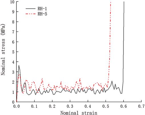
CMES, 2021, vol.127, no.1                                                                         213

obtained by taking the average value of the platform stage stress in the stress–strain curve, which
can be expressed as follows:
             εd
        1
σm =             σ (ε)dε                                                                        (7)
     εd − εy εy

                            Figure 2: Finite element model of VCRH-1

     Figure 3: Nominal stress–strain curve and energy absorption efficiency curve of VCRH

     Here, σ () represents the change in nominal stress with the strain; y represents the nominal
strain corresponding to the peak value of initial stress, which is set to be 0.02 here; and d is the
maximum strain before the material is compressed and compacted. Previous research shows that
the densification strain d is largely decided by the impact velocity and the topological structure
of the cell [23]. In order to eliminate the influence of subjective factors, the densification strain
was obtained by energy absorption efficiency method:
          ε
 d     1
               σ (ε)dε      =0                                                                   (8)
 dε σ (ε) 0              ε=εd

     As shown in Fig. 3, there are many local peaks in the energy efficiency curve. The nominal
strain corresponding to the final peak value (i.e., the point at which the energy efficiency curve
begins to decline rapidly) is regarded as the densification strain. In order to study the impact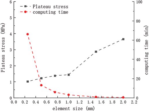
214                                                                           CMES, 2021, vol.127, no.1

resistance and energy absorption abilities of VCRH, the following key performance indicators
based on densification strain are proposed.
    A cellular material with good impact behavior should maintain impact load uniformity during
impact. In other words, the maximum stress peak value should be less than the damage critical
value, and the fluctuation of stress should be as small as possible. The impact load efficiency
(ILE) represents the impact load uniformity of cellular material, which is expressed as:
        σm
ILE =                                                                                        (9)
       σmax

    Here, σMax and σm are two parameters corresponding to the nominal stress–strain curve,
the maximum peak stress and the plateau stress. In order to obtain better energy absorption
structure, the value of σMax should be smaller and the value of ILE should be higher. For
an ideal energy absorbing structure, ILE = 1, which means σMax is equal to σm . The minimum
cushioning coefficient Cmin is an evaluation index of honeycomb structure crashworthiness, which
is defined as:
            1
Cmin =                                                                                            (10)
         ILE × εd

    Here, Cmin represents the energy absorption efficiency of honeycomb structure under the
impact load. The impact resistance of honeycomb structure is negatively correlated with the value
of Cmin.
    In order to evaluate the energy absorption abilities of honeycomb structure, specific energy
absorption (SEA) is defined as the ratio of total energy absorption to mass:
         ε            εd
       V 0 d σ (ε)dε       σ (ε)dε
SEA =                = 0                                                                    (11)
             m             ρ0
where m, V and ρ0 are the mass, volume and density of the honeycomb model, respectively.

3.3 Analysis of Mesh Sensitivity
    In this part, the accuracy and reliability of numerical simulation are verified. In order to verify
the accuracy and reliability of the finite element model, the deformation mode of traditional re-
entrant honeycomb under impact load is simulated and compared with the literature results [24].
Fig. 4 shows the deformation comparison between the simulation results and the literature results
under dynamic impact load (v = 20 m/s). When the impact velocity, material properties and geo-
metric parameters are the same, the local deformation and global deformation of the simulation
results are in good agreement with the literature results [24].
     Before the simulation, the sensitivity of the numerical results to the mesh size was analyzed.
Fig. 5 shows the effect of element size on the plateau stress and the calculation time. The results
show that when the element size decreases to 1 mm, the platform stress tends to be stable and
converges gradually. However, with the decrease in element size, the calculation time increases
rapidly. Considering the accuracy and efficiency of finite element simulation, the mesh size of
honeycomb structure is set as 0.5 mm. A large number of convergence tests show that the existing
finite element model is accurate and effective, and is suitable to analyze the dynamic characteristics
and energy absorption performance of honeycomb structures under impact load. Therefore, the
finite element model described above is reliable and can be used for subsequent research.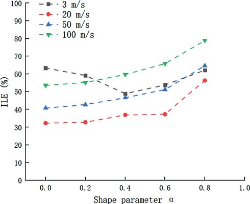
CMES, 2021, vol.127, no.1 215
(a) (b)
Figure 4: Comparison of impact deformation for traditional re-entrant honeycomb at v = 20 m/s
(a) the simulation results and (b) the reference results
Figure 5: Effect of element size on plateau stress and calculation time of VCRH
4 Results and Discussion
4.1 Deformation Mode
In order to study the influence of the cross-section change rate α on the deformation mode of
the re-entrant honeycomb structure, the in-plane impact numerical simulation with velocity of 20
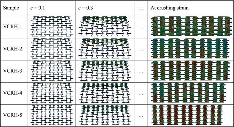
m/s was carried out for all the designed samples. Fig. 6 shows the deformation mode and stress
distribution of conventional and VCRH structures under in-plane impact. At the initial stage of
impact, when = 0.1, the deformation of honeycomb structure is concentrated on the cell unit
near the impact end, and the “necking” phenomenon occurs at the two free surfaces of the impact
end. When the strain increases gradually, the shock wave cannot propagate to the bottom of the
model in a short time due to the high velocity, so it is mainly concentrated near the impact end.
In other words, the cells closest to the impact end deform greatly, while the other cell units of
the model are not deformed to a great extent. Therefore, the cell units of the model are crushed
layer by layer.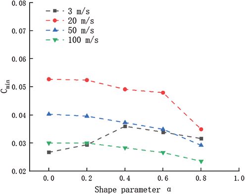
216                                                                       CMES, 2021, vol.127, no.1

      Figure 6: Deformation mode comparison of VCRH structures through simulation results

     It can be seen from Fig. 6 that the VCRH can enter the deformation mode of layer-by-
layer collapse more quickly, which means the cells nearest to the impact end are crushed more
quickly. This is mainly because the two ends of horizontal cell wall of VCRH cell are thicker,
and the strain value required for cell collapse is smaller. Fig. 7 shows the comparison of the
deformation modes of VCRH unit cells at crushing strain. Tab. 2 shows the strain of re-entrant
cellular structure under different cross-section change rates. The larger the cross-section change
rate α, the earlier the complete collapse stage appears.

          Figure 7: Deformation mode comparison of VCRH unit cells at crushing strain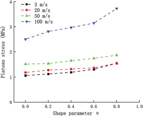
CMES, 2021, vol.127, no.1                                                                          217

                        Table 2: Crushing strain data of VCRH structures
Sample                  VCRH-1           VCRH-2           VCRH-3          VCRH-4           VCRH-5
Crushing strain         0.591            0.578            0.566           0.546            0.509

4.2 Mechanical Characteristics of VCRH
4.2.1 Young’s Modulus
     In order to obtain the elastic modulus of the structure, the quasi-static compression simulation
of the model was carried out. The total displacement of top surface of VRCH is assumed to
be 1 mm under the loading rate of 0.6 mm/min. In this case, the elastic moduli of five models
with different values of cross-section change rate α are given in Tab. 3. As can be seen, there is
a positive correlation between the elastic modulus and α.

                       Table 3: Young’s modulus values of VCRH structures
Sample                          VCRH-1           VCRH-2      VCRH-3         VCRH-4         VCRH-5
Young’s modulus (MPa)           396              437         489            556            761

4.2.2 Plateau Stress
     According to Eq. (7), the effects of cross-section change rate α and impact velocity on the
plateau stress σm of VCRH are studied. Fig. 8 shows the change in plateau stress relative to α
under different impact loads. The results show that the plateau stress of VCRH structure is greater
than that of RH structure. When the impact velocity is constant, the plateau stress increases with
α. For the honeycomb structure with the same α, the plateau stress increases with impact velocity.

Figure 8: Effect of cross-section change rate α on plateau stress of VCRH under different
impact velocities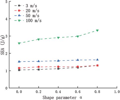
218                                                                      CMES, 2021, vol.127, no.1

4.2.3 Impact Load Uniformity
     As a critical indicator for good impact resistant structure, the impact load uniformity of
VCRH was also investigated. The dynamic response curves of VCRH structure with cross-section
change rate α = 0.8 and RH structure at v = 20 m/s are shown in Fig. 9. Due to the introduction
of variable cross-section cell wall structure, the maximum peak stress of VCRH structure is less
than that of RH structure under the same impact velocity.

                 Figure 9: Dynamic response curves of VCRH-1 and VARH-5

Figure 10: Effect of cross-section change rate α on ILE of VCRH under different impact velocities
CMES, 2021, vol.127, no.1 219
The impact load uniformity is quantified as ILE for better understanding the influence of
cross-section change rate α on the energy absorbing ability of VRCH. Fig. 10 shows the curve
of α vs ILE under different impact velocities. At low velocity impact (v = 3 m/s), ILE decreases
first and then increases with α. Especially when α = 0.8, the crush load uniformity of VCRH
structure is the same as that of RH structure. However, under the conditions of medium velocity
(v = 20 m/s, v = 50 m/s) and high-speed impact (v = 100 m/s), the impact load uniformity of
VCRH structure is better than that of RH structure, and the ILE of VCRH structure increases
with α.
4.3 Energy Absorption Characteristics
In order to evaluate the energy absorption efficiency of honeycomb structure, the minimum
dynamic cushioning coefficient (Cmin ) is proposed. Cmin is inversely proportional to the cushioning
performance of honeycomb. Fig. 11 shows the effect of cross-section change rate α on Cmin of
VCRH structure at different impact velocities. At low velocity impact (v = 3 m/s), Cmin , like the
ILE, increases first and then decreases with α. Under the conditions of medium velocity (v = 20
m/s, v = 50 m/s) and high-speed impact (v = 100 m/s), the Cmin of the new honeycomb structure
decreases with the increase in value of α. Under the condition of medium and high velocity
impact, Cmin decreases with the increase in impact velocity for re-entrant honeycomb structure
with the same α.
Figure 11: Effect of cross-section change rate α on Cmin of VCRH under different impa-
ct velocities
Fig. 12 shows the effect of cross-section change rate α on the specific energy absorption (SEA)
of VCRH under different impact velocities. The results show that the SEA of VCRH structure
is greater than that of RH structure, that is, the VCRH structure has better energy absorption
characteristics. The SEA increases with α under the same impact velocity. For the honeycomb
structure with the same α, the SEA increases with impact velocity.220 CMES, 2021, vol.127, no.1
Figure 12: Effect of cross-section change rate α on SEA of VCRH under different impa-
ct velocities
5 Conclusions
In this study, a re-entrant honeycomb with variable cross-section (VCRH) is proposed based
on the concept of variable cross-section design. Compared with the traditional re-entrant honey-
comb (RH), the impact resistance and energy absorption of VCRH are significantly improved. The
dynamic impact response and energy absorption characteristics of VCRH under different in-plane
impact velocities are evaluated by studying the micro-structure parameters. The main conclusions
of this paper are obtained by simulation analysis.
The deformation mode of honeycomb structure is determined by impact velocity and cell
microstructure. The introduction of variable cross-section into RH leads to the change in
macro/micro deformation characteristics during impact. Compared with RH, VCRH can enter the
complete collapse stage earlier. Moreover, the crushing strain of VCRH is negatively correlated
with the cross-section change rate α.
Compared with RH, the elastic modulus of the VCRH structure is significantly increased. In
addition, at the same impact velocity, the VCRH has higher dynamic platform pressure and SEA
than the RH. It is found that the RH has better impact load uniformity and energy absorption
efficiency at low speed, while the VCRH structure has better impact load uniformity and energy
absorption efficiency at medium and high speed. The results also show that the dynamic platform
pressure and SEA are positively correlated with the cross-section change rate. At medium and
high impact velocities, the impact load uniformity and energy absorption efficiency are positively
correlated with the cross-section change rate. These results can provide a reference for designing
improved auxetic re-entrant honeycomb structures.
Funding Statement: This research is supported by the National Natural Science Foundation of
China (No. 11902232).
Conflicts of Interest: The authors declare that they have no conflicts of interest to report regarding
the present study.CMES, 2021, vol.127, no.1 221
References
1. Gibson, L. J., Ashby, M. F. (1997). Cellular solids: Structure and properties. Cambridge: Cambridge
University Press.
2. Sun, Y., Li, Q. M. (2018). Dynamic compressive behaviour of cellular materials: A review of phe-
nomenon, mechanism and modelling. International Journal of Impact Engineering, 112(2), 74–115. DOI
10.1016/j.ijimpeng.2017.10.006.
3. Ren, X., Shen, J., Tranc, P., Ngo, T. D., Xie, Y. M. (2018). Design and characterisation of a
tuneable 3D buckling-induced auxetic metamaterial. Materials & Design, 139(2), 336–342. DOI
10.1016/j.matdes.2017.11.025.
4. Lim, T. C. (2015). Auxetic materials and structures. Singapore: Springer.
5. Bertoldi, K., Reis, P. M., Willshaw, S., Mullin, T. (2010). Negative Poisson’s ratio behavior induced by an
elastic instability. Advanced Materials, 22(3), 361–366. DOI 10.1002/adma.200901956.
6. Ma, Y., Scarpa, F., Zhang, D., Zhu, B., Chen, L. et al. (2013). A nonlinear auxetic structural
vibration damper with metal rubber particles. Smart Materials & Structures, 22(8), 084012. DOI
10.1088/0964-1726/22/8/084012.
7. Wu, Y., Liu, Q., Fu, J., Li, Q., Hui, D. (2017). Dynamic crash responses of bio-inspired aluminum hon-
eycomb sandwich structures with CFRP panels. Composites Part B Engineering, 121b(7), 122–133. DOI
10.1016/j.compositesb.2017.03.030.
8. Scarpa, F. (2008). Auxetic materials for bioprostheses. IEEE Signal Processing Magazine, 25(5), 128–126.
DOI 10.1109/MSP.2008.926663.
9. Xiao, D., Kang, X., Li, Y., Wu, W., Fang, D. (2019). Insight into the negative Poisson’s ratio effect of
metallic auxetic reentrant honeycomb under dynamic compression. Materials Science and Engineering: A,
763, 138151. DOI 10.1016/j.msea.2019.138151.
10. Hu, L. L., Zhou, M. Z., Deng, H. (2018). Dynamic crushing response of auxetic honeycombs under large
deformation: Theoretical analysis and numerical simulation. Thin Walled Structures, 131(10), 373–384.
DOI 10.1016/j.tws.2018.04.020.
11. Hou, X., Deng, Z., Zhang, K. (2016). Dynamic crushing strength analysis of auxetic honeycombs. Acta
Mechanica Solida Sinica, 29(5), 490–501. DOI 10.1016/S0894-9166(16)30267-1.
12. Tan, H. L., He, Z. C., Li, K. X., Li, E., Cheng, A. G. et al. (2019). In-plane crashworthiness of re-entrant
hierarchical honeycombs with negative Poisson’s ratio. Composite Structures, 229(12), 111415 1–111415 15.
DOI 10.1016/j.compstruct.2019.111415.
13. Dong, Z., Li, Y., Zhao, T., Wu, W., Liang, J. (2019). Experimental and numerical studies on the compressive
mechanical properties of the metallic auxetic reentrant honeycomb. Materials & Design, 182, 108036. DOI
10.1016/j.matdes.2019.108036.
14. Sun, Y., Pugno, N. M. (2013). In plane stiffness of multifunctional hierarchical honeycombs with neg-
ative Poisson’s ratio sub-structures. Composite Structures, 106(12), 681–689. DOI 10.1016/j.compstruct.
2013.05.008.
15. Lu, Z. X., Li, X., Yang, Z. Y., Xie, F. (2016). Novel structure with negative Poisson’s ratio and enhanced
young’s modulus. Composite Structures, 138(3), 243–252. DOI 10.1016/j.compstruct.2015.11.036.
16. Fu, M. H., Zheng, B. B., Li, W. H. (2017). A novel chiral three-dimensional material with nega-
tive Poisson’s ratio and the equivalent elastic parameters. Composite Structures, 176(9), 442–448. DOI
10.1016/j.compstruct.2017.05.027.
17. Li, D., Yin, J., Dong, L., Lakes, R. S. (2017). Numerical analysis on mechanical behaviors of hierar-
chical cellular structures with negative Poisson’s ratio. Smart Material Structures, 26(2), 025014. DOI
10.1088/1361-665X/26/2/025014.
18. Hou, J., Li, D., Dong, L. (2018). Mechanical behaviors of hierarchical cellular structures with negative
Poisson’s ratio. Journal of Materials Science, 53(14), 10209–10216. DOI 10.1007/s10853-018-2298-0.
19. Zhang, X., An, C., Shen, Z., Wu, H., Yang, W. et al. (2020). Dynamic crushing responses of bio-inspired re-
entrant auxetic honeycombs under in-plane impact loading. Materials Today Communications, 23, 100918.
DOI 10.1016/j.mtcomm.2020.100918.222 CMES, 2021, vol.127, no.1
20. Xu, C., Pang, T., Kang, H. (2019). Crashworthiness research and design of thin-walled s-shaped beams with
variable cross-section. Machinery Design and Manufacture, (2), 100–103,106.
21. Zhang, Y., Xu, X., Li, Q., Lu, M., Liao, S. (2017). Study on Crashworthiness of Novel multi cell thin-walled
structures with variable cross-section. China Journal of Highway and Transport, 30(7), 151–158.
22. Xiaofei, C., Shengyu, D., Jun, L., Weibin, W., Daining, F. (2018). Mechanical properties of an improved
3d-printed rhombic dodecahedron stainless steel lattice structure of variable cross section. International
Journal of Mechanical Sciences, 145, 53–63. DOI 10.1016/j.ijmecsci.2018.07.006.
23. Liu, Y., Wu, H. X., Wang, B. (2012). Gradient design of metal hollow sphere (mhs) foams with density
gradients. Composites Part B, 43(3), 1346–1352. DOI 10.1016/j.compositesb.2011.11.057.
24. Zhang, X. C., An, L. Q., Ding, H. M., Zhu, X. Y., El-Rich, M. (2014). The influence of cell micro-structure
on the in-plane dynamic crushing of honeycombs with negative Poisson’s ratio. Journal of Sandwich
Structures and Materials, 17(1), 26–55. DOI 10.1177/1099636214554180.You can also read