EVSE Wallbox, DIN, W16 - datasheet - openWB
←
→
Page content transcription
If your browser does not render page correctly, please read the page content below
EVSE
                                  Wallbox, DIN, W16
                                             datasheet

*) these are 3D generated models, real product can look differently and have different accessories

Last document update: July 12, 2019

                                                     1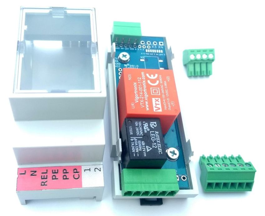
Table of Contents
Introduction.............................................................................................................................3
      Read me first.................................................................................................................3
      Theory of operation.......................................................................................................3
      Compatibility..................................................................................................................3
General description EVSE WB, DIN, W16.............................................................................4
EVSE WB - board description................................................................................................5
EVSE DIN - board description...............................................................................................7
EVSE W16 - board description..............................................................................................9
Customizations.....................................................................................................................11
      Current limitation A – using PROG pin 5.....................................................................11
      Current limitation B – using PROG pin 4.....................................................................11
      Precise current setting with Analog Input....................................................................11
      Current limitation based on PV production..................................................................11
Application examples...........................................................................................................12
      3phase wallbox with keyswitch and low tarif signal input............................................12
      3phase wallbox including a cable and plug.................................................................12
      32A EVSE with connector J1772.................................................................................14
      Recommended contactors..........................................................................................15
      Using external 12V relay.............................................................................................15
      Continuous EVSE current regulation using a pot (e.g. 6-32A)...................................16
      0 - 10V configuration...................................................................................................16
      Cable selection guide..................................................................................................17
      Customer solutions and projects.................................................................................18
FAQ......................................................................................................................................19
      1) How many PP resistors do I need?.........................................................................19
      2) EVSE does not work (config problem)....................................................................19
      3) LED indication explained.........................................................................................19
      4) How to keep current settings after grid failure?......................................................19
Advanced configuration.......................................................................................................20
      HC06 bluetooth module + Android app.......................................................................20
      Flashing new firmware.................................................................................................21
      Bootloader mode.........................................................................................................21
      Troubleshooting...........................................................................................................22
      How to determine firmware version?...........................................................................22
      Analog input control.....................................................................................................22
Firmware updates................................................................................................................26
Communication examples....................................................................................................28
      Read holding registers example..................................................................................28
      Reading the data out with Python (USB – serial adapter)..........................................28

                                                                    2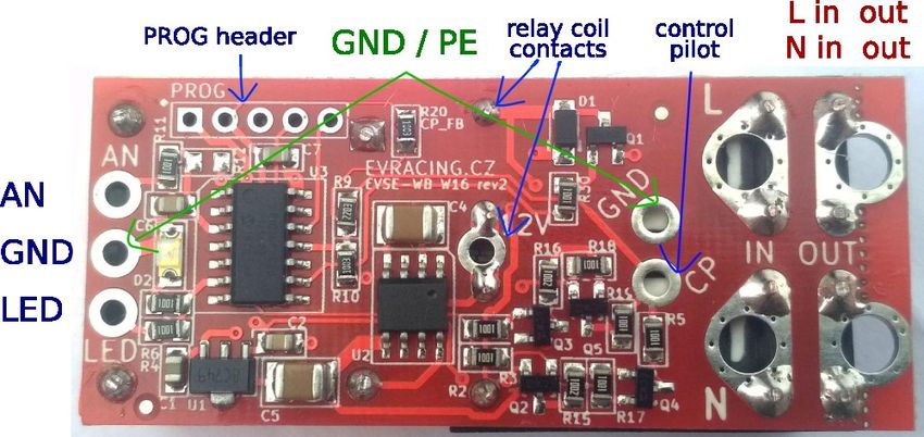
Introduction
EVSE stands for electric vehicle supply equipment. It is an element that supplies electric
energy for the recharging of electric or plug-in vehicles.
Read me first
The EVSE board is supplied with default 32A settings (or 16A for EVSE W16). Please
check the chapter “Customizations” for more information about further possibilities of
changing maximum charging current. 220 Ohm R PP is included with the kit (EVSE WB).
Theory of operation
Pilot signal duty cycle provided by EVSE defines maximum charging capacity. The car can
define several states by pulling the pilot signal down to certain voltage levels (3V, 6V, 9V).
Based on this feedback EVSE will trigger the relay for the vehicle to charge or evaluate the
state as an error (electricity will not be provided to the output socket/connector).
For more information please check:
     •   http://en.wikipedia.org/wiki/IEC_62196
     •   http://en.wikipedia.org/wiki/SAE_J1772
     •   https://github.com/kortas87/simple-evse/wiki (https://code.google.com/p/simple-evse/)

Resistance PP-PE (max cable throughput)
Resistance [ohm]                 Current limit [A]             Wire cross-section [mm2]
> 1500 *                         6                             --
1500                             13                            1.5
680                              20                            2.5
220                              32                            6
100                              63                            16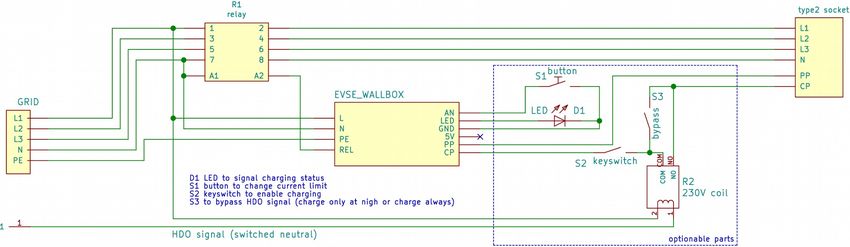
General description EVSE WB, DIN, W16
Parameters
Supply voltage                            90 – 265 VAC
Power consumption
EVSE WB - board description
Parameters
Dimension (without connectors) 60 x 30 x 25 mm
Mounting holes spacing 30 x 20 mm
Relay 5A 250V
Weight 80 g
Order code EVSE-WB
Options HC06 bluetooth, UART-USB converter
EVSE WB board has 2 connectors. 4-pin X1 for high voltage side and 6-pin for signaling
wires and control purposes. There is also PROG connector used for flashing new firmware
(ICSP), additional communication and can be further used for adjusting EVSE current (see
“Customizations” chapter).
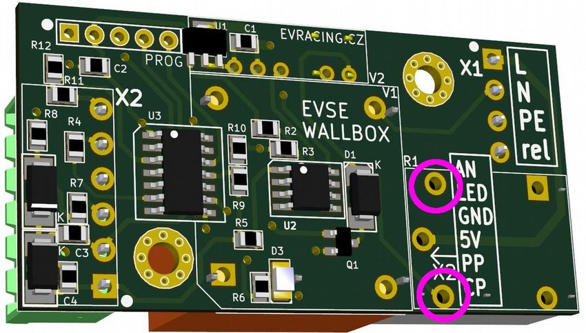
Picture 1: EVSE WB
5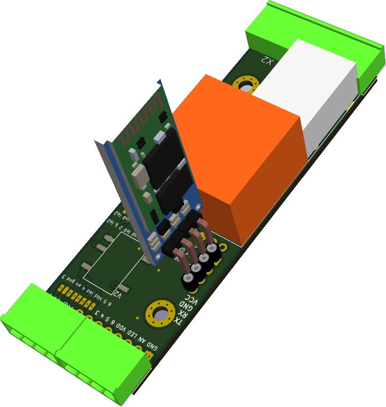
X1 connector = 4pins
pin           name               description
1: L          phase              230V power supply for EVSE board and external
2: N          neutral            contactor

3: PE         protection-earth   Ground reference
4: rel        relay output       This output drives coil of an external contactor
                                 Maximum allowed current is 3A.

X2 connector = 6pins
pin           name               description
1: CP         control pilot      To vehicle connector
2: PP         proximity pilot    To vehicle connector
3: 5V         5V power output    Used as a power supply for external components
                                 (max 40mA)
4: GND        ground             Ground reference
5: LED        external LED       Includes 1k resistor onboard, connects to LED
                                 anode against ground
6: AN         analog input       Used for button or current sensor input

PROG connector = 5pin header
pin           name               description
1             VPP                ICSP** / RFU* [marked by rectangle]
                                 from Jan 2018 bootloader enable pin
2             VDD                5V
3             GND                Ground
4             DAT / TX           ICSP** / current boost / communication function
5             CLK / RX           ICSP** / current limit / communication function
* reserved for future use
** firmware upgrade interface

                                       6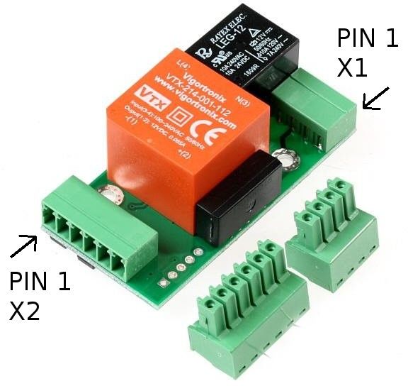
EVSE DIN - board description
Parameters
Dimension (without connectors)      86 x 29 x 25 mm
Mounting holes spacing              54 x 18 mm
Relay                               5A 250V
Weight                              85 g
Order code                          EVSE-DIN
Options                             RS485 driver, HC06 bluetooth, UART converter, 3W
                                    AC/DC

For the minimum installation you can only wire 6pin X1 connector (required:
L,N,REL,PE,PP,CP).

                                 Picture 2: EVSE DIN

                                            7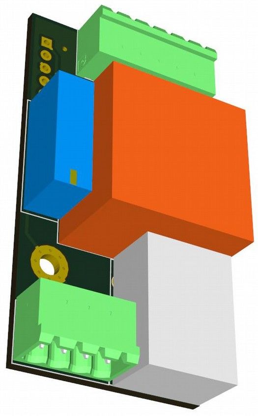
X1 connector = 6pins
pin        name                      description
1: L       phase                     230V power supply for EVSE board and external
2: N       neutral                   contactor

3: rel     relay output              This output drives coil of an external contactor
                                     Maximum allowed current is 3A
4: PE      protection-earth          Ground reference
5: PP      proximity pilot           To vehicle connector
6: CP      control pilot             To vehicle connector

X2 connector = 2pins (OPTION)
pin        name                      description
1:1                                  function defined by extension module
2:2                                  function defined by extension module

X3 connector = 4pins
pin        name                      description
1: 5V      5V power output           Used as a power supply for external components
                                     (max 40mA)
2: LED     external LED              Includes 1k resistor onboard, connects to LED
                                     anode against ground
3: AN      analog input              Used for button or current sensor input
4: GND     ground                    Ground reference

X4 connector = 4pins (OPTION)
pin        name                      description
1:3                                  function defined by extension module
2:4                                  function defined by extension module
3:5                                  function defined by extension module
4:6                                  function defined by extension module

PROG connector = 5pin header (OPTION)
same function as EVSE WB

UART connector = 4pin header (OPTION)
can be used for direct connection of HC06 (female header)

                                           8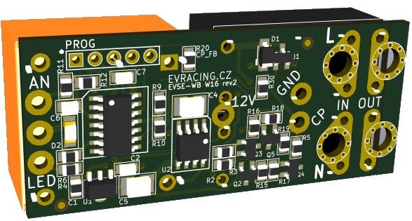
EVSE W16 - board description
Parameters
Dimension                            59 (55) x 26 x 22 mm
Relay                                2x16A 250V
Weight                               50 g
Order code                           EVSE-W16
Options                              HC06 bluetooth, UART converter

EVSE W16 is the smallest board and also includes power relays for 16A. It can be
considered as a successor of the original Simple EVSE, but with improved CP driver to
support all vehicles, new software and AC/DC + relay integration. Solderable terminals
instead of plugs keep it smaller. It can be mounted in many kinds of small boxes including
Type1 or Type2 female connectors.

                                 Picture 3: EVSE W16

                                             9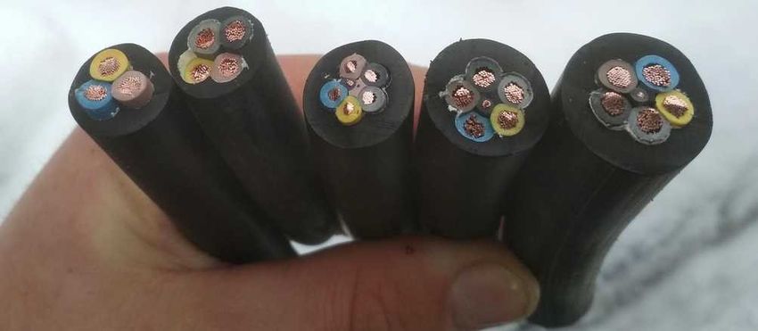
Picture 4: EVSE W16 wiring details

pins overview
pin       name                       description
L in      phase                      230V power supply for EVSE board + power input
N in      neutral
L out     phase                      switched power output for the EV connector
N out     neutral
PE        protection-earth           = GND
CP        control pilot              To vehicle connector (Type1 or Type2)
LED       external LED               Includes 1k resistor onboard, connects to LED
                                     anode against ground
AN        analog input               Used for button or current sensor input
GND       ground                     Ground reference (+ second GND between AN and
                                     LED), this is also PE reference
12V, -    relay coil contacts        can be used for adding relays for 3phase charger
                                     or using a 32A relay

PROG connector = 5pin header (OPTION)
same function as EVSE WB

                                           10
Customizations Current limitation A – using PROG pin 5 Check the table for details of how you can set the maximum current. This settings will override PIN 4 settings. PROG connector connection current limit pin5 > 4.5 V open (internal pull-up only) 32 A [default] 2.5 V < pin5 < 4.5 V 100-200k* resistor to GND 25 A 0.2 V < pin5 < 2.5 V ~3-20k* resistor to GND 16 A pin5 < 0.2 V tied to GND 10 A * resistor value may differ since internal pull-up has no defined value from production (~50k supposed), in most cases 100k for 25A and 5k for 16A is recommended Current limitation B – using PROG pin 4 Check the table for details of how you can set the maximum current. PROG connector connection current limit pin4 > 4.5 V open (internal pull-up only) 32 A [default] 2.5 V < pin4 < 4.5 V 100-200k* resistor to GND 48 A 0.2 V < pin4 < 2.5 V ~3-20k* resistor to GND 63 A pin4 < 0.2 V tied to GND 80 A * resistor value may differ since internal pull-up has no defined value from production (~50k supposed), in most cases 5k for 63A and 100k for 48A is recommended Precise current setting with Analog Input Press and hold button connected to Analog input AN of for a few seconds until LED starts to blink rapidly. Then count LED blinks which correspond to number of ampers. Please note that this limit will be set until you reboot the EVSE (make a power cycle). Button is connected the way that it pulls the signal down to ground (level
Application examples
In these application examples we suppose that customer uses appropriate contactor with
230V coil. Please check section “Recommended contactors”.
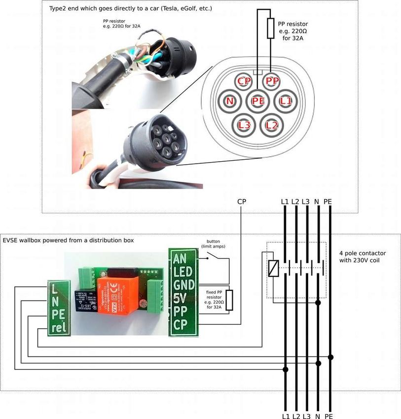
3phase wallbox with keyswitch and low tarif signal input
3phase wallbox including a cable and plug
In this example we make 3 phase Wallbox using DSIEC-2E cable. PWM duty will be
limited by the size of RPP (refer to the Theory of operation chapter). If you do not connect
any RPP current will be limited to only 6A. If your EVSE includes a cable which is fixed then
you can hard-wire RPP resistor for cable's nominal value.
12Picture 5: EVSE WB type2 fixed cable
1332A EVSE with connector J1772
With EVSE Wallbox board you can quickly build a
charging station for your Nissan Leaf 6.6kW or any other
vehicle equipped with J1772 plug.
Optional Analog Input connection:
The internal J1772 connection allows to use S1
proximity button as an auxiliary button for EVSE. With
the help of this button you can easily change charging
current with the smallest step of 1A (see Features -
Precise current setting).
Picture 6: J1772 proximity
button connection detail
Picture 7: J1772 connector - signal and power wires
14Recommended contactors
You should use relays / contactors equipped with 230V coil and connect them directly to
the board connector X1. Here are some examples which relays can be used. The most
common one (4pole contactor 25A) can be easily obtained in local electrical accessories
shop (Conrad, K&V Elektro...)
• 3-phase, maximum current 20A (e.g. Tesla 11 kW):
Noark Ex9CH25 40, Elko VS420
• 3-phase, maximum current 40A (e.g. Tesla 16.5 / 22 kW, ZOE 22 kW):
Elko VS440, Eaton Z-SCH 230V/25-40
• 1-phase, maximum current 16-20A (e.g. Peugeot iOn 3 kW, Tesla 3-4kW):
Eaton Z-R230/S
• 1-phase, maximum current 40A (e.g. Nissan Leaf 6.6 kW):
RELPOL R40N
or use normal 4-pole contactor
Picture 9: 40A 1phase relay
Picture 8: 20A 3phase relay
Using external 12V relay
In some cases it would be possible to use another 12V coil relay (maximum 0.8W coil
consumption), however this approach requires desoldering of the original relay and is
recommended only to advanced users. Automotive relays can handle sufficient currents
however their voltage rating is not high enough.
Pins marked by pink are connected to a 12V relay coil:
15Picture 10: EVSE WB - connecting 12V relay directly
Continuous EVSE current regulation using a pot (e.g. 6-32A)
Use AN as EVSE voltage input and connect a potentiometer wiper. The other two
terminals are to be connected to GND and 5V. Minimum 6A and maximum 32A can be
adjusted in registers as needed.
- set 2003 = 0 analog input current regulation
- set 2000 = 32A maximum current (AN = 5V)
- set 2002 = 6A minimum current (AN = 0V)
See the register table for more details. If you do not know how to change register values,
please check “Advanced configuration” chapter.
0 - 10V configuration
Add a 1k resistor R12. R11 is also 1k and it will create a divider 1:1. Please note that this
setup is recommended to use only with I/O modules having 0-10V analog output
galvanically isolated.
16Cable selection guide
rubber cables suitable for electric vehicles (type H07RN-F 450/750V)
type diameter current weight application
[mm] [A] [kg/m]
5G6 + 0,75 18-22 38 0.7
5G4 + 0.75 16-20 30 0.5 Type2 female 3phase charger, Type2
male to Type2 female extension cable
5G2.5 + 0.75 13-17 20 0.4
4G6 16-20 37 0.6 Type1 1phase charger, Type2 male to
Type1 extension cable
3G6 14-18 40 0.4Type1 or Type2 1phase charger with
EVSE built into the connector *)
*) other variants: 3x2.5mm 1phase, 5x2.5mm 3phase
Picture 11: 3G6, 4G6, 5G2.5+0.75, 5G4+0.75, 5G6+0.75
17Customer solutions and projects
Picture 12: 3D printer box for EVSE
WB in comparison to EVSE DIN
Picture 13: EVSE WB
in custom box with
4position current
switch
Picture 14: Charging cable made with EVSE DIN
together with 4pole contactor in a box
Picture 16: Wifi interface for EVSE WB
Picture 15: SDM630 electric meter + (https://github.com/CurtRod/SimpleEVSE-
EVSE DIN RS485, web interface (http:// WiFi)
openwb.de)
18FAQ
1) How many PP resistors do I need?
As described in more detail above in the schematic (page 12), there must be one resistor
in Type2 female (car side) and other resistor connected to an EVSE. Both are usually part
of the extension cable Typ2 female (car side) to Type2 male (EVSE side). When using a
fixed cable (not possible to disconnect from the EVSE) then the size of EVSE PP resistor
can be “hardcoded” (modbus versions only, see register 2007 below) or a resistor of a
fixed size have to be connected (usually 220 ohm for 32A cable).
2) EVSE does not work (config problem)
Make sure that the EVSE is not turned off (2005 configuration register). If the board does
not respond at all, make sure the the UART parameters are correct (9600 baudrate,
RX/TX+GND wired correctly). Did not the Modbus address change by accident (reg.
2001)?
Any kind of software / firmware / settings problem can be solved using a PicKIT and
reprogramming the board from scratch using MPLAB IPE (do not forget to erase the chip
too!). PicKIT 4 can be bought on Farnell (https://uk.farnell.com/search?st=pickit%204).
EVSE firmware is ready for download from this link:
http://evracing.cz/evse/evse-wallbox/fw_pickit/ .
Parameters and options:
- chip name is PIC16F1825
- “power target circuit from tool” (use 2-2.5V)
- “use high voltage program mode entry”
- pin1 is always marked (both on Pickit and the board too)
- if “power target circuit from tool” does not work, power the board externally
3) LED indication explained
Using the pin LED you can directly connect LED to indicate EVSE status. The output
includes 1k resistor. External LED has the same indication function as on-board LED.
LED connection
1x fast + pause pilot signal is steady +12V, no vehicle connected
2x fast + pause PWM signal is generated, vehicle is present
1x long + pause vehicle requested power, contactor is ON
20x fast in 0.5s enter or leave current setting mode
1x each 0.3s current setting mode – one more amper set
3x fast + pause EVSE is disabled in software, FW >=6
5x fast + pause pilot signal check failed (no charging), FW >=11
194) How to keep current settings after grid failure?
- see “advanced configuration” and enable communication (if necessary), see NOTE#1
- see HC06 bluetooth module + Android app
- set 2004 = 1 to save current set by button OR
- set 2000 = “desired amp value” to keep this maximum current every time
20Advanced configuration
Beginning January 2018 all boards can be configured by MODBUS. By default MODBUS
interface is disabled and old functions of PROG pins are kept. However you can enable it
by grounding PIN4 and PIN5 of PROG connector while powering the board up please see
NOTE#1 instead.
Physical layer is not galvanically isolated UART (0-5V) or optionable isolated RS485 EVSE
DIN only.
The default device ID is 1 (can be changed in register 2001).
Some values can be then read or written over MODBUS protocol. PROG pin header is
used for this purpose with following pinout:
PROG connector connection
pin3 GND
pin4 TX
pin5 RX
This feature is useful for further development and testing with EVSE Wallbox board and
can be also a great way to interface other devices such as Raspberry PI, Ethernet UART
bridges (e.g. WIZnet or USR serial-to-ethernet boards), various WiFi modules etc.
HC06 bluetooth module + Android app
Preferred way is to use HC06 Bluetooth converter and Android application developed for
this purpose. By default the communication is disabled (see NOTE#1 below register table),
because the original analog functions of RX,TX pins are kept (for changing current by
resistors).
You can download and install the app from here (*.apk extension): http://evracing.cz/evse/
evse-wallbox/
HC06 is connected to PROG connector.
1. power up the board, HC06 should start blinking
2. pair your Android device with the adapter (default pin 1234)
3. open the EVSE app and choose the paired bluetooth adapter in its settings
4. hit connect button and wait for connection
5. read & write registers you need
21Flashing new firmware
Flashing new firmware using Android phone is supported (with bluetooth adapter) on all
EVSE DIN devices and on EVSE Wallbox devices only with “modbus firmware”. In order to
flash new version of firmware bootloader mode must be enabled (last bit of the register
2005 - see the below).
Bootloader mode
If bootloader mode is activated the LED is solid on or off and it toggles when there is active
communication. Bootloader mode can be turned off by changing the configuration register
or it happens automatically after successful flashing of new firmware or there is a timeout
of approximately 4 minutes.
When bootloader mode is activated, modbus slave address is set to 1.
The other way to enter bootloader mode is to keep analog input down when the device is
booting (before powering on) for about 12 seconds (CHECK: or some more complicated
way to prevent accidental bootloader turn on? CONCLUSION: if divider 1:1 used for AN =>
colision, result: this option disabled)
Bootloader change with board having initial revision 10: bootloader can be enabled by
pulling MCLR (pin 1 PROG header) down for at least 12 seconds. This is needed for the
case that software upgrade fails and there is no possibility to enable bootloader by
changing the register.
22Troubleshooting
If the download of a new firmware was not completed then you need to try it again,
otherwise the board will not function properly. Last chance to fix badly programmed board
is using PICKIT programmer (you can order PicKIT 4 on Farnell to get it fast).
How to determine firmware version?
If you power up the EVSE board and the LED is on for about 2 - 3 seconds you have
Modbus firmware onboard and it is disabled. You can enable it this way NOTE#1.
Firmware revision can be then read from register 1005.
Analog input control
Charging current can be changed based on analog input AN voltage (when register 2003 =
0). Minimum value is set in register 2002 and maximum in register 2000. Default supported
range is 0 - 5V. Analog input is referenced to GND and is not isolated
Charging current (IPWM) for the vehicle is calculated:
IPWM = UAN / 5 * IMAX
Where UAN is the voltage measured at the input AN and IMAX is actual maximum current.
Default is 32A, however it can be adjusted by settings or “current boost” / ”current limit”
feature or change in configuration register.
If the resulting current is smaller than 6A then the EVSE state will change to “pilot steady
12V” and vehicle stops charing. Minimum current can be also adjusted in the register.
23Register table
Register R/W def Description
address ault
1000 R/W Actual configured amps value (from reg 2002 to 80A)
1001 R Actual amps value output
1002 R Vehicle state:
1: ready
2: EV is present
3: charging
4: charging with ventilation
5: failure (e.g. diode check)
1003 R 6 / 13 / 20 / 32 / 63 / 80 A
Maximum current limitation according to a cable based on PP
resistor detection
1004 R/W bit0: turn off charging now
bit1 - bit15: not used
1005 R Firmware revision
1006 R EVSE state
1: steady 12V
2: PWM is being generated
(only if 1000 >= 6)
3: OFF, steady 12V
... ...
2000 R/W 32 Default amps value after boot (max 80A, min 6A)
2001 R/W 0 Function of PROG PIN 4 + 5, slave address
(default 0: current limit or boost functions available)
0: analog inputs enabled
> 0: MODBUS communication enabled
This value also means the slave address.
2002 R/W 5 Minimum amps value, allowed 0 - 13
if set to 0 the EVSE will completely stop charging during
analog input mode (2003 = 0) and AN = 0V
24Register R/W def Description
address ault
2003 R/W 1 Analog input config:
0: analog input current regulation, input 0 - 5V corresponds to
the range:
minimum amps --> default amps
note that there is a weak pullup resistor enabled for this input
(no input connected --> 5V)
1: each blink 1 amp step (default), starts from 0
2: each blink 2 amps step, starts from 0
3: each blink 3 amps step, starts from 0
.....
10: each blink 10 amps step, starts from 0
11: mapping table: registers 2010 - 2017
1x blink = value from 2010
2x blink = value from 2011
...
2004 R/W 0 Amps settings after power on (applies only to a changes made
by the button), whether to save amps settings to eeprom each
time it changes or not
0 - do not save amps value (default)
1 - save amps value to register 2000 every time it changes
2005 R/W 1 bit0:
Enable button for current change (no sense when 2003 = 0)
0: disabled
1: enabled (default)
bit1:
Stop charging when button pressed
0: disabled (default)
1: enabled
charging will automatically start after you manually unplug and
plug the cable to the vehicle
bit2-12: reserved
bit13: disable EVSE after charge (write 8192)
bit14: disable EVSE (write 16384)
bit15: enable bootloader mode (write 32768)
NOTE: if both bit0 and bit1 are enabled then “interrupt
charging” will have higher priority, when charging
2006 R/W 0 RFU: Current sharing mode is active
(two or more EVSEs connected to a single breaker)
0 - charging current is half of the default current
amps > 0: this amps value will be used
2007 R/W 0 PP detection
0: PP detection enabled (default)
value > 0: detection disabled, fixed PP limit entered [A]
25Register R/W def Description
address ault
2008 R/W reserved
2009 R Bootloader firmware revision
2010 R/W 6 Amps value 1
2011 R/W 10 Amps value 2
2012 R/W 16 Amps value 3
2013 R/W 25 Amps value 4
2014 R/W 32 Amps value 5
2015 R/W 48 Amps value 6
2016 R/W 63 Amps value 7
2017 R/W 80 Amps value 8
Register addresses are in decimal format!
NOTE#1: By default MODBUS is NOT enabled, so the original analog input switches can
be used (current limit and current boost functions). MODBUS can be enabled by pulling
AN input down to GND while booting (= when you power the device up) at least 5 times
within 3 seconds seconds (button activated). This will change register 2001 to the value 1,
but it will not save the value permanently. Value will be saved after first successful R/W
operation over MODBUS (register number >=2000).
NOTE#2: You can restore default settings of all registers by saving a value 65535 to the
register 2010
NOTE#3: Only functions 03 (Read Holding Registers) and 16 (Preset Multiple Registers)
are implemented. For more details please check: http://www.simplymodbus.ca/FAQ.htm
RFU: reserved for future use
26Firmware updates
2019-04-26 revision 12:
- RX buffer limit fix (mainly for RS485 systems)
2018-12-10 revision 11:
- improved CP signal check (implements status E), requires feedback resistor 100k (rev3
board R20, rev2 board R13, DIN version R21)
- if you do not upgrade feedback resistor, do not use firmware 11+
2018-10-30 revision 10:
- fix evse status register 1002 initial value (probably caused problems in OpenWB)
- modbus timeout set to 5 steps
2018-08-28 revision 9:
- combined code for EVSE DIN 485 and EVSE WB (but 2 different hex files)
- uart communication fix (RX overflow error check)
- weak pullup disabled for PP detection pin
- modbus timeout set to 3 steps
2018-02-06 bootloader v3:
- fix: removed reconfiguration from bootloader code (causing rewriting reg 2002)
2017-11-18 bootloader v2:
- added possibility to turn bootloader on by hardware pin 1 (Vpp/MCLR)
2017-11-18 Androi app v2:
- fixed .hex file parser (firmware upgrade), always use latest app version for firmware
flashing!
2017-10-31 revision 8:
- added “disable EVSE after charge” bit (register 2005)
- fixed issue with voltage AN input - now follows minimum amps and does not turn off
2017-06-23 revision 7:
- interrupt routine rewritten (modbus communication)
- correct vehicle status update, if pwm is not being generated
- modbus timeout set to 20 steps
2017-06-07 revision 6:
- new configuration bits, register 2005 (disable EVSE, interrupt charging, change current)
- error code signalization
2017-05-03 revision 5:
- fixed current limit based on cable PP resistor (and analog pin input)
2017-04-26 revision 4:
- fixed amps value from AI (e.g. for max 32A reached only 31A and 5V input)
27- fixed minimum amps value (was not taken into account)
2017-04-21 revision 3:
- added bootloader (Android application)
- fixed bug with analog input not working while modbus enabled
- added control register 1004
2017-04-13 revision 2:
- changeable slave address in reg 2001
- stop charging button function reg 2005 (no timeout, but wait for unplug & plug), bitfield
introduced for more possible options
- added register 1005 (firmware revision number)
2017-02-17 revision 1:
- initial version
28Communication examples
Read holding registers example
01 03 03 E8 00 02 AA 2D (request)
bytes description
01 The slave address (always 01 unless changed by customer)
03 Function code (03 is for read holding registers function)
03 E8 The data address of the first register to read
00 02 The total number of registers requested.
AA 2D CRC (cyclic redundancy check)
01 03 04 8F B5 8F BA B4 0F (answer)
bytes description
01 The slave address (always 01)
03 Function code (03 is for read holding registers function)
04 The number of data bytes to follow (2 registers x 2 bytes each = 4)
8F B5 The contents of register 1000 (36789 → 3678.9 mV)
8F BA The contents of register 1001 (36794 → 3679.4 mV)
B4 0F CRC (cyclic redundancy check)
Reading the data out with Python (USB – serial adapter)
You can use almost any MODBUS master utility for Windows / Linux / Mac. For common
users we recommend using QModBus (http://qmodbus.sourceforge.net/). There is also
QModMaster (http://sourceforge.net/projects/qmodmaster/) utility, but there may be a
problem with write multiple registers function (there is bug in the software which causes
register shift) - so use it carefully.
Advanced users can use Python / pymodbus (https://github.com/bashwork/pymodbus) for
further development or similar libraries.
In following example we read out first 7 registers
#!/usr/bin/python3
from pymodbus.client.sync import ModbusSerialClient
client = ModbusSerialClient(method = "rtu", port=”/dev/ttyUSB0, baudrate=9600,
stopbits=1, bytesize=8, timeout=1)
rq = client.read_holding_registers(1000,7,unit=1)
print(rq.registers)
#Reading the data out with Python (USB – serial adapter)
29You can also read