SOUNDWAVE FAST, EFFICIENT, INNOVATIVE - Improve Your Workflow, Enhance Your Productivity
←
→
Page content transcription
If your browser does not render page correctly, please read the page content below

FAST, EFFICIENT, INNOVATIVE

SOUNDWAVE™
Improve Your Workflow, Enhance Your Productivity
SOUNDWAVE
                                                         Quick Reference Cards

Contents
 1   Programming Guidelines: . .  .  .  .  .  .  .  .  .  .  .  .  .  .  .  .  .  .  .  .  .  .  .  .  .  .  .  .  .  .  .  .  .  .  .  .  .  .  .  .  .  .  .  .  .  .  .  . 2
     New Patient . .  .  .  .  .  .  .  .  .  .  .  .  .  .  .  .  .  .  .  .  .  .  .  .  .  .  .  .  .  .  .  .  .  .  .  .  .  .  .  .  .  .  .  .  .  .  .  .  .  .  .  .  .  .  .  .  .  .  .  .  .  .  .  .  . 4
     Return Patient . .  .  .  .  .  .  .  .  .  .  .  .  .  .  .  .  .  .  .  .  .  .  .  .  .  .  .  .  .  .  .  .  .  .  .  .  .  .  .  .  .  .  .  .  .  .  .  .  .  .  .  .  .  .  .  .  .  .  .  .  .  . 7

 2   Neptune Programming Guidelines . .  .  .  .  .  .  .  .  .  .  .  .  .  .  .  .  .  .  .  .  .  .  .  .  .  .  .  .  .  .  .  .  .  .  .  .  . 9

 3   Harmony™ Upgrade for C1 Implant Recipients . .  .  .  .  .  .  .  .  .  .  .  .  .  .  .  .  .  .  .  . 14

 4   Bilateral Patient Management . .  .  .  .  .  .  .  .  .  .  .  .  .  .  .  .  .  .  .  .  .  .  .  .  .  .  .  .  .  .  .  .  .  .  .  .  .  .  .  . 18

 5   Clinical Programming Tools. .  .  .  .  .  .  .  .  .  .  .  .  .  .  .  .  .  .  .  .  .  .  .  .  .  .  .  .  .  .  .  .  .  .  .  .  .  .  .  .  .  .  .  . 24

 6   NRI Steps and Procedures . .  .  .  .  .  .  .  .  .  .  .  .  .  .  .  .  .  .  .  .  .  .  .  .  .  .  .  .  .  .  .  .  .  .  .  .  .  .  .  .  .  .  .  .  . 28

 7   NRI Troubleshooting . .  .  .  .  .  .  .  .  .  .  .  .  .  .  .  .  .  .  .  .  .  .  .  .  .  .  .  .  .  .  .  .  .  .  .  .  .  .  .  .  .  .  .  .  .  .  .  .  .  .  .  . 33

 8   Performing NRI in the OR. .  .  .  .  .  .  .  .  .  .  .  .  .  .  .  .  .  .  .  .  .  .  .  .  .  .  .  .  .  .  .  .  .  .  .  .  .  .  .  .  .  .  .  .  .  . 35

 9   Program Window Keyboard Shortcuts . .  .  .  .  .  .  .  .  .  .  .  .  .  .  .  .  .  .  .  .  .  .  .  .  .  .  .  .  .  .  . 39
1

                   Programming Guidelines:
               New Patients and Return Patients

            SOUNDWAVE
                   Programming Quick Reference Cards

2 Programming Guidelines
Programming Guidelines
Get Started
      • Launch SoundWave™.

   Software
   Options
                                                  Fitting Hardware

                                                            Management Grid

                  Action
                  Pane
                                                                  Preview Pane

                                                                                                Programming Quick Reference Cards
      • C
         onnect the sound processor to the fitting hardware and place the headpiece on the
        patient’s head.
          o Check the Fitting Hardware Task Group in the Ribbon Bar.
          o The task group should indicate the implant is ready.

       Tip: Click on an icon in the Fitting Hardware task group to access hardware options.
       For example, click on the sound processor to initialize or backup the sound processor.

3 Programming Guidelines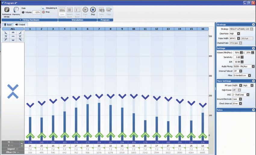
Programming Steps: New Patient

   Step 1: Create the Patient File
           • Select New in the Action Pane, enter the required information, and select OK.
           • The New Implant Window will open. Enter the required information and select OK.

   Step 2: Condition Electrodes
           • Select the Impedances Tab and then click on Condition Right or Condition Left in the
              Action Pane. Alternatively, select to Run Conditioning from the implant icon in the Fitting
              Hardware Task Group.

           Impedances run by default when communication is established between the patient file and the
           implant, and following Conditioning.

   Step 3: Create Programs
           • Go to the Programs Tab and select New Right, New Left, or New Bilateral in the Action
              Pane.

          Example: Program Window

Input Tab: Gain                            Save, Copy, and                                 Program Parameter
  Adjustments                              Close Programs                                        Groups

                                                                                                                Programming Quick Reference Cards
Shaping
 Tools

Global
 Tool

Auto T

                                                                                                   Frequency
                                                                                                   Allocation

   4 Programming Guidelines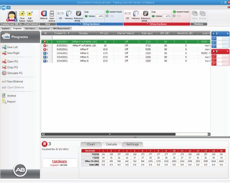
• Select a Strategy (HiRes – P is the default).
       • Verify Audio Mixing in Settings. Consider the following and refer to the SoundWave
          manual for detailed information on Audio Mixing:
           o T-Mic™ program: Select Aux Only
           o Program for use with FM or External Aux input: Select 50/50 – Mic/Aux
       • Volume and Sensitivity dial setting
           o Harmony™, PSP, and PBTE

                                                             During programming, if the sound processor
                                                             has a Volume or Sensitivity dial, this read out
                                                                      will reflect the dial setting.

            o Neptune™

                                                               Neptune Volume and Sensitivity dials are
                                                              on the Neptune Connect, which is removed
                                                              during programming.  Therefore, these dial
                                                               settings are managed in the Ribbon Bar.

        In all cases, the read out in the Ribbon Bar is an absolute value between -100 and +100%
        independent of the program Volume and Sensitivity Settings.

       • Set M levels with Speech Burst™ or Live Speech stimulation (Speech Burst is the default).

                                                                                                               Programming Quick Reference Cards
       • Fine tune the settings, for example: increase the Input Dynamic Range from 60dB to 80dB
          to improve access to softer sounds or manage Gains from the Input Tab.
       • Save the Program
            o Select Save and Close from the Program task group. The program will be assigned an
               ID in the Patient Management Window.
            o Create additional programs. Highlight a program and select Copy from the Action
               Pane or follow the previous steps for a new program.

        Remember: A program remains editable until loaded to a sound processor, a report is gener-
        ated, stimulated on within the Patient Record Window, or the patient file is closed.

Step 4: Initialize Processor
        • Initialize to prepare the sound processor for programming or to download programs.
              o Select Initialize from the Processor Pane or the Fitting Hardware Task Group.
              o Enter the serial number if it is not already populated (optional).
              o Select side from the drop-down menu to assign processor for Left, Right, or Both ears.
              o Select Yes.

5 Programming Guidelines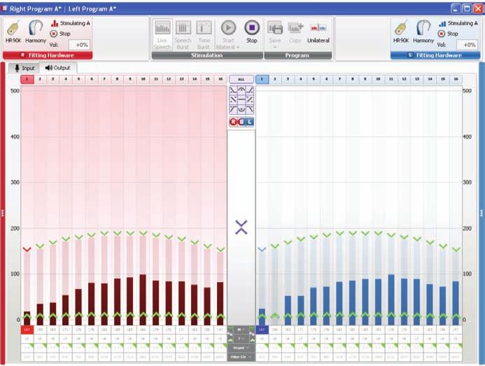
Step 5: Download Programs
        • Click and drag or type the program ID into the desired program slot in the Processor Pane.
        • Manage LEDs and/or alarms on a program-by-program basis as available in the sound
           processor by clicking on the status LED in the Processor Pane. *Status LED and alarm
           details for associated sound processors are available in the SoundWave manual.
        • Click Download in the Processor Pane.

Step 6: Generate Reports
The following reports are available in SoundWave: Program, Visit History, Impedance, and NRI.
        • To generate a report, go to the associated tab.
            o For example, to generate a program report, go to the Programs Tab.
        • Select the items in the Management Grid that will be included in the report.
            o For example, highlight programs 1, 2, and 3 in the Management Grid.
        • Click on Report in the Action Pane.
        • Select Print or Save.  Reports can be saved as a .PDF.

                                                                                                       Programming Quick Reference Cards

6 Programming Guidelines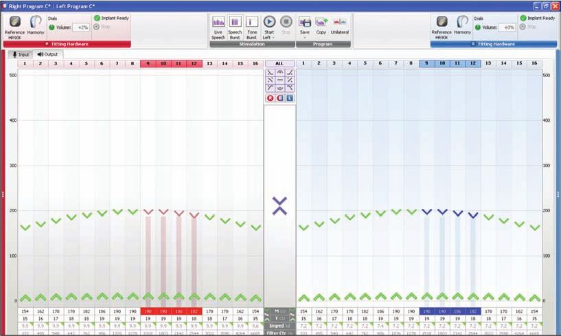
Programming Steps: Return Patient

Step 1: Open the Patient File
        • Select the patient name from the Patient Management Grid.
          If this is a transfer patient, the patient name may be listed in the Action Pane.
        • Double click on the name or choose Open from the Action Pane.

Step 2: Review Impedances
        • Impedances will run automatically by default when the patient file is opened and commu-
           nication (lock) established with the implant.

Step 3: Manage Programs
        • Select a program from the Patient Record Window and Copy or Open. Alternatively, select
           New and create a new program.
        • Manage settings. Consider the following and refer to the SoundWave™ manual for detailed
           information on strategy, settings, and program management:
             o Audio Mixing
                 - T-Mic™ program: select Aux Only
                 - Program for use with FM or External Aux input: select 50/50 – Mic/Aux
             o Volume Range
                 - Disable volume control using -/+ 0% volume range
             o Sensitivity
                 - Create environmental-specific programs by modifying this up to -/+ 10 dB
             o Internal Telecoil (Harmony™ only)
                 - Enable with appropriate Audio Mixing and provide access to auxiliary input via

                                                                                                           Programming Quick Reference Cards
                 telecoil compatible devices
             o Input Dynamic Range
                 - Expand to provide access to softer-level sounds and enhance music listening
        • Save the Program
             o Select Save and Close from the Program task group. The program will be assigned an
                ID in the Patient Management Window.
             o Create additional programs. Highlight a program and select Copy from the Action
                Pane or follow the previous steps for a new program.

        Remember: A program remains editable until loaded to a sound processor, a report is generated,
        stimulated within the Patient Record Window, or the patient file is closed.

Step 4: Download Programs
        • Initialize the sound processor as required.
        • Click and drag or type the program ID into the desired program slot in the Processor Pane.
        • Manage LEDs and/or alarms on a program-by-program basis as available in the sound
           processor by clicking on the status LED in the Processor Pane. *Status LED and alarm
           details for associated sound processors are available in the SoundWave manual.
        • Click Download in the Processor Pane.

        Load a back-up sound processor from the Visit History tab: click, drag, and drop a Visit History
        record onto the Processor Pane. Click Download.

7 Programming Guidelines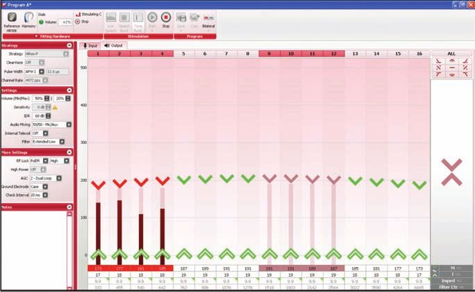
Step 5: Generate Reports
        • To generate a report, go to the associated tab.
            o For example, to generate a program report, go to the Programs Tab.
        • Select the items in the Management Grid that will be included in the report.
            o For example, highlight programs 1, 2, and 3 in the Management Grid.
        • Click on Report in the Action Pane.
        • Select Print or Save. Reports can be saved as a .PDF.

Managing a Version 1 Sound Processor:
Data on a sound processor programmed in a previous version of SoundWave (e.g., version 1.1, 1.4, or
1.6) can be imported to the patient database.

The database will update with the imported information, and the sound processor icon will no longer
display “Version 1” once initialization has been performed. Follow these steps:

                                         Click on the sound

                                                                                                      Programming Quick Reference Cards
                                         processor and then
                                       Import Version 1 Patient
                                     from the drop down menu.

  Additional information is available in the associated manuals and user guides. Should you have
 questions or need programming support, please contact the Advanced Bionics Audiologist-On-Call
       at 877.271.6727 (within the US and Canada) or contact your local AB representatives.

8 Programming Guidelines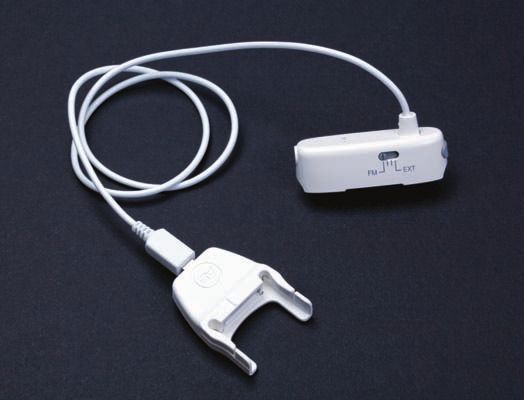
2

          Neptune Programming Guidelines

            SOUNDWAVE
                   Programming Quick Reference Cards

9 Neptune Programming Guidelines
Neptune Programming Guidelines
Neptune Sound Processor
Flexible wearing options, advanced signal processing, and a waterproof design make Neptune™ an
excellent choice for both pediatric and adult implant recipients.* Programming steps for Neptune will
be similar to those followed with previously released sound processors from Advanced Bionics with a
few distinctive considerations, which are outlined below.
*Compatible with the HiRes 90K, and CII Bionic Ear™ internal devices.
Fitting Hardware Configuration
The Neptune sound processor connects to the Clinician’s Programming Interface (CPI) utilizing the
Platinum Series™ Processor (PSP) Programming Cable, the Neptune Programming Cable Adapter,
and the Neptune Programming Cable.
Neptune
Programming
Cable
Programming Quick Reference Cards
Programming
Neptune Programming
Header
Cable Adapter
• Connect the Neptune Programming Cable as follows (the associated user guide provides
additional detail):
o Connect the PSP Programming Cable to the Neptune Programming Cable Adapter.
o Connect the Neptune Programming Cable to the Adapter.
o Remove the Neptune Connect or color cover from the Neptune sound processor.
o Push the programming header snugly onto the Neptune sound processor. The circle
on the underside of the header must align with the circular depression on the top of
the Neptune sound processor.
Circular depression on Neptune
sound processor
Note: To remove the programming header, press the release latch until the header disconnects
from the Neptune sound processor.
10 Neptune Programming Guidelineso Verify that the Neptune sound processor appears in the SoundWave™ Fitting
Hardware Task Group.
Programming Neptune
Neptune supports programming parameters and sound processing strategies that are available
and approved for use with the Harmony™ sound processor including CIS, MPS, HiRes-P, HiRes-S,
Fidelity 120™, and ClearVoice™. Following are unique considerations for programming the Neptune
sound processor.
Volume and Sensitivity
• In fitting mode, Neptune does not have an available volume or sensitivity dial; therefore,
adjustments are made via the Ribbon Bar. The sensitivity information in the Ribbon Bar
overrides the sensitivity setting in the Program Window.
Type a value into the field or use
the up/down arrow to adjust.
• Similar to other Advanced Bionics sound processors, volume range and sensitivity can be
set on a program-by-program basis. For example:
Programming Quick Reference Cards
o Disable the Volume Dial for a specific program: Set the Volume (Min/Max) in the
Program Window Settings to -/+ 0.
o Manage the Sensitivity Dial for a specific program:
- The Neptune Connect sensitivity dial is enabled by default. The sensitivity dial
overrides a program-specific sensitivity setting.
- To allow the recipient to utilize a program-specific sensitivity setting (-/+ 10 dB)
disable the Neptune Connect sensitivity dial in the Processor Pane prior to
download.
Select the arrow next to the program slot number and click to manage
the sensitivity. ✓ = Neptune Connect sensitivity dial is active and
overrides the program’s sensitivity setting. No check = Neptune Connect
sensitivity dial is inactive and the program’s sensitivity setting is active.
11 Neptune Programming GuidelinesPhonak MLxi and Battery-Operated External Audio Input
During programming of a Neptune sound processor, Live Speech stimulation with real-time parameter
adjustments is possible for an auxiliary input. Follow these steps:
• With Neptune attached to the Neptune Programming Cable and visible in the Fitting
Hardware Task Group, connect the Phonak MLxi receiver or external audio input device
per the steps outlined in the Neptune Programming Cable instructions for use.
• In the Program Window under settings, select Audio Mixing:
Audio Mixing
o Aux Only = Aux input on at 100%; Mic input off
o 50/50 = Equal level from Mic input and Aux input
o 30/70 = Mic input is approximately 10 dB less than Aux input
o Aux Only (Atten.) = Aux input reduced by 20 dB; Mic input off
• Set the switch on the programming header to FM for the Phonak MLxi receiver or EXT for
a battery-operated external audio input device.
Programming Quick Reference Cards
FM / EXT
programming switch
• Select Live Speech stimulation from the Stimulation Task Group and select Start. Be aware
that settings on the FM or external audio device may impact the sound delivered to the
recipient.
If the recipient does not hear FM input, verify that:
o A Mic-only setting is NOT being used as the Audio Mixing setting in the active
program in SoundWave.
o The programming header switch is in the FM position.
o The FM transmitter has been synced with the FM receiver.*
*Important: The Phonak MLxi should be programmed for an Advanced Bionics sound
processor via the Phonak SuccessWare. Programming support is available through the AB
Audiologist-On-Call.
12 Neptune Programming GuidelinesIf the recipient does not hear input from the external audio device, verify that:
o A Mic-only setting is NOT being used as the Audio Mixing setting in the active
program in SoundWave.
o The programming header switch is in the EXT position.
o The external device is powered and set to an adequate volume level.
Neptune Processor Pane Options
Processor Pane options include status LED, audible alarms, and lock. In addition, there are options
only available with Neptune.
• Status LED and audible alarms Default settings:
Alarms disabled
LED enabled
Click the symbol(s) to enable.
Program Slot Options
• Clear Slot: Provides the ability to remove an already downloaded program from a specific
program slot.
• Stimulate: Provides the ability to stimulate a specific program from the Processor Pane.
• Aux Source has three options: Auto-Detect, EXT, and FM.
Programming Quick Reference Cards
o Auto-Detect: This is the default setting and allows Neptune to automatically accept
FM input* or Aux input from a device connected to the 3.5 mm Auxiliary Connector.
FM input takes precedence over Aux input if both are connected to Neptune Connect.
*FM receiver and transmitter must be synced
o EXT: Transmits only input from a device connected to the 3.5 mm Auxiliary Connector
as the Aux input. (No input from FM.)
o FM: Transmits only FM input to the recipient as the Aux input. (No input from a device
connected to the 3.5 mm Auxiliary Connector).
• Enable/Disable Sensitivity (described under managing volume and sensitivity) on a
program-by-program basis.
• Enable/Disable IntelliLink™: Available on a program-by-program basis. This is an important
safety feature for AB recipients. Contact the AB Audiologist-On-Call or your Clinical
Specialist before disabling.
Additional information is available in the associated manuals and user guides. Should you have
questions or need programming support, please contact the Advanced Bionics Audiologist-On-Call
at 877.271.6727 (within the US and Canada) or contact your local AB representatives.
13 Neptune Programming Guidelines3
Harmony™ Upgrade for C1 Implant Recipients
SOUNDWAVE
Programming Quick Reference Cards
14 Harmony™ Upgrade for C1 Implant RecipientsHarmony™ Upgrade for C1 Implant Recipient
Getting Started
Print Program(s) from SCLIN.
Step 1: Open SoundWave™.
Step 2: Select New and enter patient and implant information.
Electrode array information is
found in the upper right-hand
corner of the SCLIN Report.
IntelliLink™ is not an available
option for a C1 implant.
Programming Quick Reference Cards
Select OK when done.
Step 3: Run Impedances and review values.
un impedances from the Fitting Hardware Task Group in the Ribbon Bar or the Impedance Tab.
R
By default, impedances will automatically run when a patient record is opened and the fitting
hardware is locked to the implant.
15 Harmony™ Upgrade for C1 Implant RecipientsStep 4: Initialize the Harmony™ sound processor.
Click on Harmony™ in
the Fitting Hardware task
group and then
Initialize Processor from
the drop-down menu.
Step 5: Create a program.
• Open a New Right or a New Left Program from the Action Pane in the Programs Tab.
• Enter the program settings from the SCLIN report.
o Select strategy and settings in the Action Pane.
o Enter Adjusted M and T levels from the SCLIN report.
Important: When creating a program for a patient with an S-Series sound processor, select the
Programming Quick Reference Cards
S-Series Filter setting and the S-Series AGC.
Step 6: Verify comfort in Live Speech.
• Select Live Speech Stimulation.
• Turn down the volume control on the sound processor or reduce M levels globally. Start
stimulation.
• Gradually increase the sound processor volume control. Alternatively, slowly increase
M levels to the user comfort level.
• Adjust program settings for sound quality.
16 Harmony™ Upgrade for C1 Implant RecipientsStep 7: Set the RF level.
• Set RF level
o Start Live Speech stimulation.
o Decrease the RF value until lock is lost (Live Speech Stimulation stops).
o Increase RF by two or three steps and restart stimulation.
o Live Speech Stimulation should resume. Introduce a loud sound, such as clapping.
Lock should be maintained, if not then increase RF one step and restart stimulation.
Introduce a loud sound. Repeat until lock is maintained.
This level is expected to provide stable lock for the user; however, verify that stable lock is
maintained in stand-alone (on battery power) before the patient leaves the clinic.
Step 8: Save and Close the Program
Step 9: Create Additional Programs as Desired
Programming Quick Reference Cards
• Highlight the saved program from the Patient Record Window.
• Select Copy from the Action Pane.
• Consider:
o A program with telecoil active and an Audio Mixing setting of 50/50.
o A program for T-Mic™ use with an Audio Mixing setting of Aux Only.
Step 10: Download Programs to Harmony™.
The Status LED is
enabled/disabled by
clicking on the LED
prior to Download.
Additional information is available in the associated manuals and user guides. Should you have
questions or need programming support, please contact the Advanced Bionics Audiologist-On-Call
at 877.271.6727 (within the US and Canada) or contact your local AB representatives.
17 Harmony™ Upgrade for C1 Implant Recipients4
Bilateral Patient Management
SOUNDWAVE
Programming Quick Reference Cards
18 Bilateral Patient ManagementBilateral Patient Management
Management and programming of your bilateral patients have been elevated to new levels of care in
SoundWave™. Using SoundWave, you can program both ears simultaneously in real-time, manage
programs and hardware within the same Patient Record, and easily view or update patient details.
The Patient Record Window for a Bilateral Recipient
Verify hardware Initialize, download,
Click to view/edit patient
connections and set LEDs/alarms
information specific to
quickly for for ear-specific sound
each ear within a single
processors with
patient record. both ears. one click.
Programming Quick Reference Cards
View and manage programs
for R & L ears.
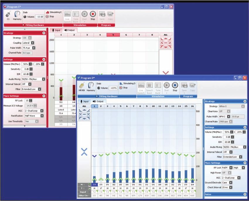
19 Bilateral Patient ManagementThe Bilateral Program Window*
Stimulate, Save, and Copy programs
Right Ear Left Ear
Fitting Fitting
Hardware Hardware
Click to Click to
expand the expand the
Strategy Strategy
and Settings and Settings
Panes. Panes.
Global Modifier Tools
Programming Quick Reference Cards
Stimulate, Save, and Copy programs:
Purple means that options are available for both the right and left ear.
Click to choose a
stimulation mode.
Click Start Bilateral to
see a drop down menu
of stimulation options.
*This feature available for HiRes 90K™ and CII implants only
20 Bilateral Patient ManagementFocus:
Focus for bilateral, right ear only, or left ear only stimulation. Program changes can be done with live
stimulation, in real-time and are implemented on the ear or marker with focus:
• Select side from the Global Tools for stimulation.
Bilateral Right Side Left Side
Focus: Focus: Focus:
Choose ‘B’ Choose ‘R’ Choose ‘L’
Programming Quick Reference Cards
• After selecting the area of focus for stimulation, refine the selection for adjustment by
clicking on a level marker.
Bilateral
focus for Refined focus for
stimulation. level adjustment.
21 Bilateral Patient ManagementSynchronous Task Management for Bilateral Patients
Running Conditioning (CII/90K Recipients Only)
Measuring Impedances
Programming Quick Reference Cards
Initializing the Sound Processor
Downloading to the Sound Processor
22 Bilateral Patient ManagementProgramming Bilateral C1+CII/90K Recipients
Management of a C1+CII/90K recipient in SoundWave is similar to management of a bilateral
CII/90K recipient. There is one important exception: to create a bilateral view of programs and make
program adjustments to both, open two fitting windows (one for each implant), start stimulation for
each, and independently modify program parameters.
Programming Quick Reference Cards
23 Bilateral Patient Management5
Clinical Programming Tools
SOUNDWAVE
Programming Quick Reference Cards
24 Clinical Programming ToolsClinical Programming Tools
Sweep and Balance
Sweep and Balance utilizing Tone Burst or Speech Burst™ stimulation modes.
Sweep
Programming Quick Reference Cards
Balance
Sweep: Delivers alternating stimulation across three or more selected electrodes or speech burst
bands in an apical to basal direction.
Balance: Delivers alternating stimulation between two selected electrodes or speech burst bands.
Note: The stimulation of adjacent electrodes is not required to sweep or balance.
25 Clinical Programming ToolsSteps to Sweep and Balance:
Step 1: Open a new or saved program.
Step 2: Select Speech Burst or Tone Burst in the Stimulation Task Group.
Step 3: Select the electrodes or speech burst bands for stimulation by clicking on the electrode
contact number at the top of each channel in the Program Window.
Note: The first electrode or Speech Burst selected retains focus.
Step 4: Open the drop-down menu below the Start button to refine the stimulation level:
Set stimulation level based on % M level
Set number of presentations per electrode or Speech Burst band
Step 5: Select Start
Sweep and Balance Tips:
• Increase the number of presentations to allow more time to observe the patient response
on each electrode or speech burst band.
Programming Quick Reference Cards
• The electrode or speech burst band with focus responds to keyboard commands, such as “s”
to start stimulation, ▲ arrow to increase stimulation, and ▼ arrow to decrease stimulation.
• Focus to a new electrode or speech burst band by clicking on a channel marker or using
the left and right arrow keys.
• Adjustments to stimulation level can be done in real-time during stimulation.
• The Global Tool simultaneously adjusts all enabled electrode M or T levels.
Electrodes selected
for balancing.
Focused Global
M levels Tool
26 Clinical Programming ToolsElectrode Management Options
From the Program Window, right-click over the electrode contact or speech burst band to be
managed. SoundWave™ displays the following menu:
Electrode Contact Menu
• Electrode: Enable or disable selected electrodes.
• Clipping: Enable clipping to prevent stimulation from exceeding a specified level.
• Interpolation: Enable interpolation on one or more electrodes to establish M levels based
on measured values in the Program Window. This option is available only in Live Speech or
Tone Burst stimulation.
• tNRI: Display or hide tNRI markers.
Frequency Allocation Tables
Extended Low Filter (default setting)
Standard Filter
Programming Quick Reference Cards
Center frequency information is available on the Output/Input Tabs of the Program Window and full
frequency information is found in the Program Report.
27 Clinical Programming Tools6
NRI Steps and Procedures
SOUNDWAVE
NRI Quick Reference Cards
28 NRI Steps and ProceduresNRI Steps and Procedures
NRI Measurement Window
Parameter
Settings
Indicates Data Point is selected
for N1/P2 adjustment
To enlarge individual tracings,
double-click on the tracing or
select a tracing and click on
the three small triangles
Key
Indicates data point is included in the EP Growth Function
Indicates data point is excluded from the EP Growth Function
Represents N1
NRI Quick Reference Cards
Represents P2
Indicates data point is selected
NRI Measurement Tab
Management Grid
Action
Pane
Preview Pane
29 NRI Steps and ProceduresStep 1: Enter NRI Measurement Settings
Stimulating Electrode
• Select a stimulating electrode.
Note: If only conducting NRI measurements on a subset of electrodes, select electrodes that are
distributed across the electrode array, such as 3, 7, 11, and 15.
Recording Electrode
• Set the electrode that SoundWave™ will use to measure the response during the NRI
measurement.
o The default setting is 2 apical unless the stimulating electrode is at the apical end of
the array.
Note: Do not use extracochlear electrodes, electrodes with shorts, electrodes with opens, or elec-
trodes exceeding compliance limits when conducting NRI measurements.
Stimulation Range:
NRI Quick Reference Cards
• Set the starting and ending stimulation levels in Clinical Units (CU) as desired.
o The default setting is from 100–200 CUs.
Note: Stimulation Range may be set as ascending or descending.
Data Points
• Set the number of points to achieve an increment step size of 20–30 CU.
o The default setting is 5 data points.
Stimulation Sequence
• Set the polarity of the pulse used during NRI stimulation.
o The default is Cathodic First.
Averages per Data Point
• Set the number of stimulus presentations that will be delivered and averaged at each
stimulation level.
o The default is 128 averages.
30 NRI Steps and ProceduresRecording Gain
• Set the gain applied by the recording amplifier.
o The default is 300.
Note: Recording Gain may need to be increased if NRI responses are noisy.
Step 2: Run and Save NRI Measurement
• Select Start from the Recording Task Group in the Ribbon Bar.
• NRI will run on each data point until completion of the NRI measurement.
Note: Select Next, found in the Data Point Task Group on the Ribbon Bar, to move on to the next
data point if a response is obtained before 128 averages are completed.
• Select Save from the NRI Measurement Task Group in the Ribbon Bar.
Step 3: Using Interpolation to Create Programs Based on NRI
• After completing NRI, go to the Programs Tab.
NRI Quick Reference Cards
• Select New Right or New Left from the Action Pane to open a new program. If tNRI values
are not displayed in the Fitting Window, perform the following steps to display them:
o Right-click on any electrode.
o Select tNRI – Show All.
Note: By default, tNRI values will not display in a program window; however, this can be
changed in Preferences.
31 NRI Steps and Procedures• Select Live Speech or Tone Burst from the Stimulation Task Group in the Ribbon Bar.
• Right-click on any electrode and select Interpolation – Enable All.
o Select Yes when a pop-up window is displayed asking if you would like to only interpo-
late zero value channels.
• Set M levels for electrodes with tNRI measurements.
• Electrodes with set M values now have filled M markers and become anchors for interpolation.
o M levels for the non-anchor electrodes will be automatically set based on the M levels
for anchor electrodes.
• Lower the volume control on the sound processor or reduce M levels globally and turn on
stimulation.
• Gradually increase volume control or M levels to user settings.
Note: M levels may be set initially at the more conservative 10–20% below tNRI. After verifying
comfort at the initial setting, increase Ms while monitoring performance.
• Verify settings (using Ling Sounds, for example).
• Select Save from the Program Task Group in the Ribbon Bar.
Step 4: Create Additional Programs Based on NRI
NRI Quick Reference Cards
Use the following recommendations for creating programs using the data obtained using NRI.
If tNRI is7
NRI Troubleshooting
SOUNDWAVE
NRI Quick Reference Cards
33 NRI TroubleshootingNRI Troubleshooting
If NO NRI response is obtained, try the following:
1. Connect a Platinum Series™ sound processor (body worn), if you are not already using
one, and repeat the measure.
2. Change the Recording Electrode. Start with the closest neighboring electrode (+1 apical,
then basal).
3. Increase the number of averages.
4. Increase the maximum stimulation level.
5. Change the Stimulating Electrode and perform the NRI measurement on a different
electrode.
For a clinical programming session, these additional troubleshooting steps may apply:
6. Increase Stimulation Range by 25 CU (set this new level in both Stimulation Range boxes
and set to collect 1 Data Point).
7. Continue to increase in increments of 25 CU as needed. Do not exceed 600 CU (based on
average compliance limits) or exceed compliance limits for stimulation of the selected
electrode. Exceeding compliance limits is indicated by a warning message that appears to
the right of the Stimulation Range.
NRI Quick Reference Cards
e cautious. Watch patient for any behavioral response suggesting stimulation is
B
uncomfortable or loud.
Additional information is available in the associated manuals and user guides. Should you have
questions or need programming support, please contact the Advanced Bionics Audiologist-On-Call
at 877.271.6727 (within the US and Canada) or contact your local AB representatives.
34 NRI Troubleshooting8
Performing NRI in the OR
SOUNDWAVE
NRI Quick Reference Cards
35 Performing NRI in the ORPerforming NRI in the OR
Getting Started
Set up fitting equipment as shown in the photo below. Be sure to connect the Clinician’s Programming
Interface (CPI) to the power supply and to the computer. Then, connect the sound processor to the
CPI via the programming cable.
PC with SoundWave Professional
Suite Software
CPI
Headpiece
Programming
Cable
PSP with Cable lock attached
Step 1: Open SoundWave™ and Select New in the Action Pane.
NRI Quick Reference Cards
Step 2: Input Patient Information and Implant Information and select OK.
Patient Information Implant Information
36 Performing NRI in the ORStep 3: Place the headpiece on the recipient’s head. Confirm that the fitting hardware (CPI,
Processor, and Implant) is recognized as shown below.
Step 4: Run Conditioning and review impedance values for each electrode.
NRI Quick Reference Cards
Important: It is recommended that NRI is run on valid (green) electrodes only.
Step 5: Go to the NRI Measurements Tab and select New Left or New Right from the Action Pane.
37 Performing NRI in the ORStep 6: Under Settings, select the Stimulating Electrode from the drop-down menu. Set the Stimulation
Range from 400 CU–50 CU. Use the default values for the remaining parameters.
If the error message below
appears next to the Stimulation Range,
reduce the upper stimulation level
Step 7: Select Start in the Recording Task Group in the Ribbon Bar. As the measurement is running,
look for an NRI response (shown below).
Step 8: After a response is visible, stop stimulation by selecting Pause in the Recording Task Group
in the Ribbon Bar or by pressing the Space Bar on the keyboard. The presence of an NRI
NRI Quick Reference Cards
response confirms that the auditory nerve responded to stimulation from the selected
stimulating electrode.
Step 9: Select Save or Save and Copy (if you would like to make additional NRI measurements) in
the Program Task Group in the Ribbon Bar.
• Run NRI on additional electrodes as desired.
Step 10: Select Save and Close when NRI measurements are complete.
Additional information is available in the associated manuals and user guides. Should you have
questions or need programming support, please contact the Advanced Bionics Audiologist-On-Call
at 877.271.6727 (within the US and Canada) or contact your local AB representatives.
38 Performing NRI in the ORSOUNDWAVE
Program Window Keyboard Shortcuts
FUNCTION KEY
Adjust All Markers Down Page Down
Adjust All Markers Up Page Up
Adjust Markers Down (M,T, Clipping, Gains) Down Arrow
Adjust Markers Up (M, T, Clipping, Gains) Up Arrow
Bilateral Window: Focus Left Side L or Ctrl + Left Arrow
Bilateral Window: Focus Right Side R or Ctrl + Right Arrow
Data Entry 0–9
Move Entire Channel Selection to the Left Alt + Left Arrow
Move Entire Channel Selection to the Right Alt + Right Arrow
Move Selection Left Left Arrow
Move Selection Right Right Arrow
Select All Markers Ctrl + A
Select Clipping Marker C
Select Gain Marker G
Select M Marker M
Select Multiple Channels to the Left Shift + Left Arrow
Select Multiple Channels to the Right Shift + Right Arrow
Select T Marker T
Toggle Input/Output Tab I/O
Toggle Stimulation On/Off S
39 Keyboard ShortcutsGLOBAL HEADQUARTERS
Advanced Bionics, LLC
28515 Westinghouse Place
Valencia, CA 91355 USA
+1.877.829.0026
+1.661.362.1400
+1.661.362.1500 Fax
info@AdvancedBionics.com
MANUFACTURER
Advanced Bionics, LLC
12740 San Fernando Road
Sylmar, CA 91342 USA
+1.877.829.0026
+1.661.362.1400
+1.661.362.1500 Fax
info@AdvancedBionics.com
INTERNATIONAL HEADQUARTERS
Advanced Bionics AG
Laubisrütistrasse 28
8712 Stäfa, Switzerland
+41.58.928.78.00
+41.58.928.78.90 Fax
International@AdvancedBionics.com
EU REPRESENTATIVE
Advanced Bionics SARL
76 rue de Battenheim
68170 Rixheim, France
+33.3.89.65.98.00
+33.3.89.65.50.05 Fax
europe@AdvancedBionics.com
ASIA PACIFIC
Advanced Bionics
Asia Pacific Limited
Suite 4203, 42/F, Tower One
Lippo Centre, 89 Queensway
Hong Kong
+852.2526.7668
+852.2526.7628 Fax
AP@AdvancedBionics.com
LATIN AMERICA
Advanced Bionics Sucursal Colombia
Carrera 7 No. 83-29
Ofinica 902
Bogota, Colombia
+571.691.59.00/05/14
+571.621.84.42. Fax
LA@AdvancedBionics.com
028-M020-03
ClearVoice is not approved nor available for sale in the United States. ©2011 Advanced Bionics, LLC and its affiliates. All rights reserved.You can also read