Davit Arm Installation Manual - July 2021 Revision 1.1 - lation Manual - Bettersafe International
←
→
Page content transcription
If your browser does not render page correctly, please read the page content below
Davit Arm
Installation Manual
July 2021
R e v i s i o n   1 . 1

                          I n s t a l l a t i o n     M a n u a l
                                        J u l y     2 0 2 1   v 1 . 1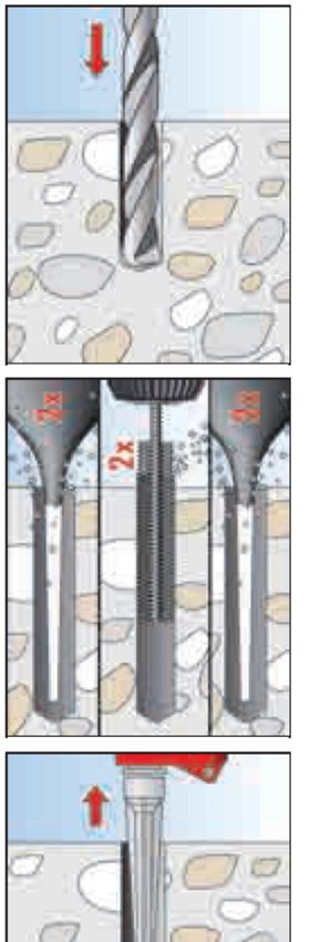
2

Installation Manual

 WARNING!
 • This manual is invalid if any unauthorised alteration has occurred.
 • Unauthorised use of this manual may lead to prosecution
 • This manual was, to the best of our knowledge, correct at its date of issue.
 • It is the user’s responsibility to ensure that all subsequent authorised amendments are incorporated
    and that the manual is to the current issue status.
 • A manual that is not to the latest issue status is invalid and must not be used.

 Contents

 Introduction                                                                                     3

 Typical System Layout & Positioning Criteria                                                     4
         Maximum & Minimum Reach and Height                                                       4
         Clearance over edge protection                                                           5
         Optimum System Layout                                                                    6

 General Fixing Information                                                                       7

 Ordering System Components & Tools                                                               8

 General Installation Information                                                                 9
        Socket Installation                                                                       9
        General Information                                                                       10

 Installation                                                                                     14
           General Information                                                                    14
           System Description                                                                     16
           Surface Mount – to concrete using FIS VT Resin and Studding                            17
           Surface Mount – to concrete using FH II Mechanical Anchor and Studding                 18
           Cast In                                                                                19

                                                                     I n s t a l l a t i o n      M a n u a l
                                                                                      J u l y   2 0 2 1   v 1 . 1
3

Introduction
General Information

   The Axxess Davit Arm System from Bettersafe International BV is designed specifically for the Rope
   Access Industry.

   Designed to be used as a re-direction anchor for live and back up systems the Davit Arm has a
   reach of maximum 1,957mm whilst still at a use height of 1,875mm

   A rope access re-direction davit arm is an accessory to an anchorage device designed to remove
   the risk of ropes running over an edge, and to facilitate the easy access and egress for the worker.
   This socket is permanently attached to the structure and is designed to protect one or more
   people during work at height and the removeable arm is designed in such a way as to offer them
   maximum freedom of movement.

   As with any anchorage device anyone connecting to the Axxess Davit Arm System must use Fall
   Protection PPE in conformity with the current regulations.

   The equipment authorised on the system must be written in to the operator’s manual which will be
   given to the end user and must appear on the sign plates near the lifeline. If the system is used
   with a different PPE from the one recommended the result may be an incompatibility of equipment
   with layout causing the system to be unsuitable for use and potentially dangerous.

   The system complies with the current standards and requirements:
   Europe: EN 795:2012, CEN / TS 16413:2016, BS 8610:2017 Tested independently by SATRA.

                                                                  I n s t a l l a t i o n      M a n u a l
                                                                                   J u l y   2 0 2 1      v 1 . 1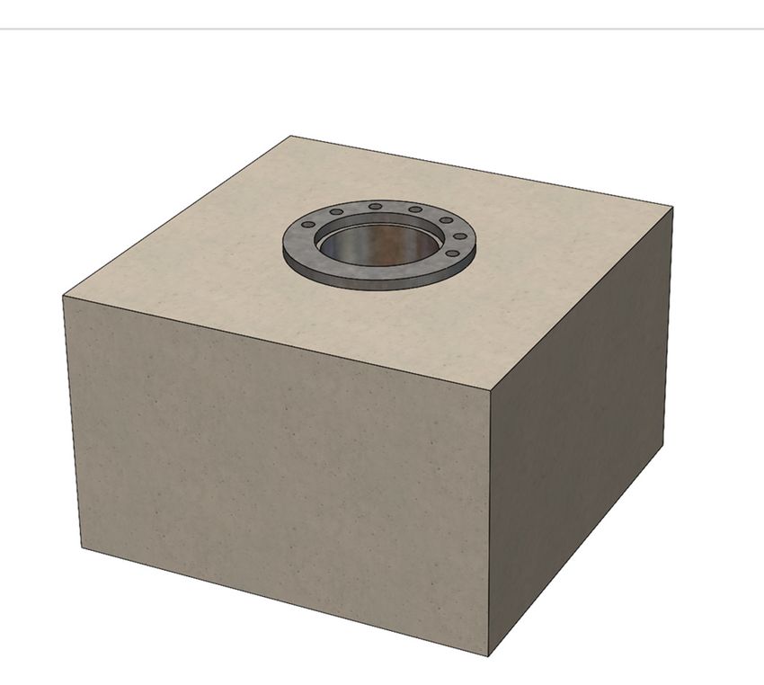
4

Typical System Layout & Positioning Criteria
Surface Mount shown for example purposes.

Maximum & Minimum Reach and Height

                                            1,489

                                            1,957

  2,238

          1,875

                                                    I n s t a l l a t i o n     M a n u a l
                                                                  J u l y     2 0 2 1   v 1 . 1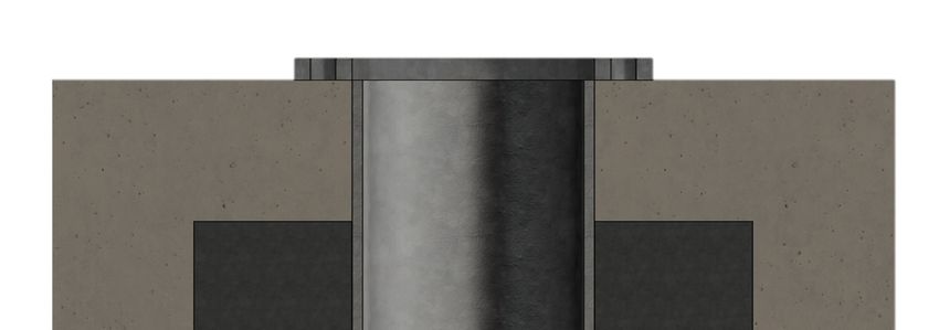
5

Typical System Layout & Positioning Criteria
Surface Mount shown for example purposes.

Clearance over edge protection

                                                                  1100

                                            745

                                                                    1100

                                              1035

                                                     I n s t a l l a t i o n     M a n u a l
                                                                   J u l y     2 0 2 1   v 1 . 1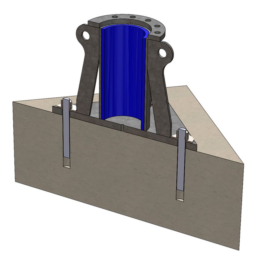
6

Typical System Layout & Positioning Criteria
Surface Mount shown for example purposes.

Optimum System Layout

                                            1222

                                                   1957

        3000

                                               1489

                                                          I n s t a l l a t i o n     M a n u a l
                                                                        J u l y     2 0 2 1   v 1 . 1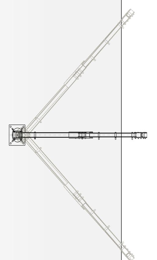
7

General Fixing Information
Guidance Only

    The sockets can be attached to various structures:

    • In all cases the structure must be investigated and subsequent calculations completed to ensure that the
      structure will withstand the calculated forces, including a safety factor of two (2).
    • The hardware to be used (nuts, bolts, washers) of all the components of the lifeline must be 316 stainless
      steel with minimum strength of 70 kg/mm2 (or A4 70 minimum) unless otherwise supplied by Bettersafe
      International.
    • Fixings shall be M16 with a complete installation minimum of 21kN per pair of fixings.

                           Concrete /      Steel
       Type of Structure                                                        Comments
                            Masonry      Structure

       Expansion Bolts          X                    According to manufacturer’s recommendations

        Chemical Plugs          X                    According to manufacturer’s recommendations

                                                     With the agreement of the building/structure owner and
            Bolting                         X
                                                     structural investigation

                                                                           I n s t a l l a t i o n            M a n u a l
                                                                                             J u l y    2 0 2 1     v 1 . 1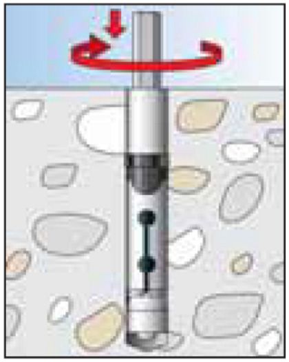
8

Ordering System Components & Tools
General Information

   System components
          When components are required, please contact Bettersafe International quoting relevant
          part number from the list. Guidance is provided in the component explanatory notes.
          Orders should be sent to orders@bettersafeinternational.com

   Amendments
   1.    Bettersafe International reserve the right to continually update their range of products and
         manufacturing processes, in the interests of reliability, durability and performance
   2.    In this respect, this installation and servicing manual will need occasional updating. Bettersafe
         International shall issue all registered holders the relevant amendments.
   3.    If in any doubt regarding the current Issue Status of a manual, please contact Bettersafe
         International.

                                                                    I n s t a l l a t i o n       M a n u a l
                                                                                     J u l y    2 0 2 1      v 1 . 1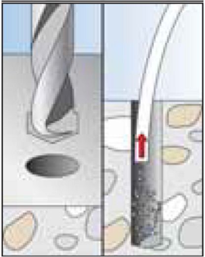
9
                                                                                                                      9

General Installation Information
Socket Installation

   Socket Installation
   Depending upon the socket type there are multiple ways that installation can be achieved.
   When installing the socket it is important to ensure that the top face is as level as possible, with
   installation being not more than 3 degrees misaligned from the horizontal.
   Socket installation should only be carried out by a competent person. If specifying the anchors, resin,
   fasteners, or any combination of the afore mentioned, it is essential that the competent person is of
   ability to specify an installation that is safe for use. If in any doubt about the calculation of loads
   contact your Bettersafe International representative.
   Verifying the Installation
   Bettersafe International strongly recommends testing the installation of the socket before initial use;
   especially when using resin bonded anchors.
   When verifying the installation, we recommend that it is tested to a maximum force of 6kN at the
   devices maximum radius if used for the lifting of personnel.
   If only used for the lifting of goods we recommend testing to no greater than 125% of the goods’
   WLL at its maximum radius. All tests should be carried out in all anticipated worst-case loading
   directions, sustained for a duration of 3 minutes.
   If unable to test the installation then each anchor can be isolated and tested individually applying the
   applicable loading, i.e. tension and/or shear loads.
   For clarification on the loads contact your equipment supplier.
   If an installation differs from the sockets referred to above or to that specified by your supplier then
   the competent person must verify by calculation that the installation can withstand:
   •    For Rope Access, 15kN at the device’s maximum radius in all anticipated worst-case loading
        directions but not test to more than 6kN at the device’s maximum radius (If Applicable)
   •    For lifting of goods, 150% of the goods WLL at the device’s maximum radius in all anticipated
        worst-case loading directions, but not test to more than 125% of the goods WLL at the device’s
        maximum radius
   •    If required a sacrificial anchor may need to be installed to verify the installation has the ultimate
        capacities required.
   Following initial socket installation verification tests, we do not recommend overload tests for the
   socket or davit and suggest thorough visual examination only. If the client feels that because of a
   visual examination that a load test is appropriate, we recommend a 100% load test and certainly no
   greater than 125%.

                                                                     I n s t a l l a t i o n       M a n u a l
                                                                                       J u l y   2 0 2 1    v 1 . 1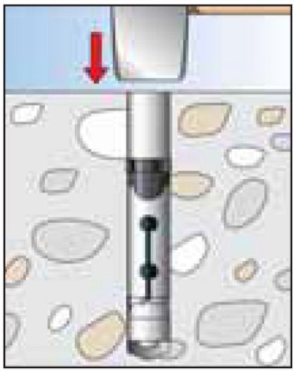
10

General Installation Information
General Information

   1.     Procedures
          To prevent injury to personnel, and damage to the system, read, understand and comply
          with the procedures as detailed in this manual.
   2.     Installation Approval
          Only Bettersafe International authorised installers are allowed to install and service the
          Axxess Davit System.
   3.     Traceability
          All components of the system can be traced back to source.
   4.     Componentry
          Only use approved components when erecting systems and when replacing worn or
          damaged items. If other parts are used, they may be of inferior or different dynamic
          specification and may cause incorrect operation of the system.
          Bettersafe International cannot accept liability in this respect.
          Modifications and alterations of components are not permitted without prior written
          agreement from Bettersafe International.
   5.     System Modifications
          If the system must be modified because of a site requirement, during or after installation,
          which causes a deviation from the original configuration, then the anchorage forces and fall
          distances will have to be recalculated for the modified system.
   6.     Fall Protection
          When working at height whilst installing the System, use an independent means of fall
          protection.
          When servicing a System, do not attach to it if it has sustained a fall or if it has been
          damaged. Use an independent means of fall protection.
   7.     Calibration
          When using equipment involving measurement (e.g. torque wrench, tension tester,
          micrometer), only use calibrated articles traceable to National Standards.

                                                                     I n s t a l l a t i o n     M a n u a l
                                                                                   J u l y     2 0 2 1   v 1 . 1
11
General Installation Information
General Information
8. Entry/Exit from System
It is important to remember that until a user has fully connected to the system, that person
is not fully protected from falling.
Accordingly, where possible, the entry/exit point should always be sited in a position of
safety. This will minimise the risk of falls during system connection.
If this objective cannot be achieved, then additional precautions must be considered.
For example, a safety barrier or fence could be erected from access point to entry-exit
point. Alternatively, anchorage points could be installed to provide a means for additional
fall arrest protection.
9. Anchorage alignment
When designing the layout of the system it is imperative that the reach of the davits and the
clearance of any obstacles is taken into account to prevent fouling.
Rescue locations also need to be considered to allow neighbouring davits to be used for
rescue where possible.
Location of the sockets should be such that the worker can access the system and then
move to the façade in a safe manner.
10. Anchorage Loadings
The loadings should be communicated to the client for confirmation that the support
structure is capable of withstanding the forces that would be applied in the event of a fall on
the system.
I n s t a l l a t i o n M a n u a l
J u l y 2 0 2 1 v 1 . 112
General Installation Information
General Information
17. Units of Measurement
Where measurement abbreviations are used in this manual, the following definitions apply:
kN (kilonewton) - SI unit of load or force
mm (millimetre) - SI unit of length
m (metre) - SI unit of length
kg (kilogram) - SI unit of mass
Nm (Newton-metre) - SI unit of torque
18. Limitations
Maximum number of persons for fall arrest purposes. This is noted on 1 (Arm)
system label 2 (Base)
Maximum mass of each person attached to system including 140kg
equipment and clothing.
I n s t a l l a t i o n M a n u a l
J u l y 2 0 2 1 v 1 . 113
General Installation Information
General Information
Note: Anchorages
In accordance with EN795 the system requires a minimum safety factor of 2 on all anchors.
This is based on the ratio of the anchor fittings ultimate load to computed dynamic load (in
the direction of force).
Example: - If a dynamic load of 6kN has been predicted, then the corresponding anchor
must be able to withstand 12kN in the direction of force.
All anchor bolts must be able to withstand a minimum of 12kN for this installation with a
combined installed load minimum of 21kN in the weakest direction depending on the
substrate.
Note:
Bettersafe International strongly recommend that all anchors are fitted in accordance with
the manufacturer’s instructions for use, and with the installation requirements of EN
795:2012, TS 16415:2013 & BS 7883:2019.
I n s t a l l a t i o n M a n u a l
J u l y 2 0 2 1 v 1 . 114
Installation
General Information
Foreword
The nature of the following text is instructional on the installation attachment of the Axxess Davit
Arm System. It does not detail anchors, anchor bolts, or plates, or any type of anchorage system to
be employed. Selection of structural anchorages is a function of the mounting structure material,
potential system forces, and the environment. As such the selection must be made by the
competent Engineer in charge of the system installation. A competent engineer is defined as: -
‘A person who has a recognised Structural or Civil Engineering qualifications, and who has had
adequate previous installation experience.’
Such an Engineer must have attended Bettersafe International training and be familiar with the
Axxess Davit Arm System
This manual does not automatically infer design approval to or for particular system configurations.
This must be obtained from architectural or site authority as appropriate, before commencement of
work.
Pre-requisite Installation requirements
Installation cannot take place until the following have been fully considered and completed.
Site Plan
A site plan must be drawn up to indicate the Davit System configuration, to include: -
• Extremities
• Entry / exit access points
• Obstacles
• Rescue Planning
• Direct Anchorage Location
I n s t a l l a t i o n M a n u a l
J u l y 2 0 2 1 v 1 . 115
Installation
General Information
Calculations
A calculation must be performed on the finalised system configuration, using the appropriate
Bettersafe International approved procedures. This will provide the installation Engineer with the
maximum anchorage forces, which could be generated in the event of a fall.
Component List
An appropriate list of components must be drawn up, including cable lengths, in order to fulfil the
contract.
Personnel
The installation team must be competent by way of qualifications, training and experience. They
must also have knowledge, and be familiar with the Davit system.
I n s t a l l a t i o n M a n u a l
J u l y 2 0 2 1 v 1 . 116
Installation
System Description
The design of the Axxess Davit Arm System is such that when any user is attached, full 360 degree
movement can be enjoyed in the work zone whilst being securely connected to a safety system. In
the event of a fall, the faller will be arrested.
With a large reach and clear height above the user, and 15 adjustments on the height and reach,
the system is extremely versatile
General Layout: -
The system consists of a base and a removeable arm. With a choice of surface mounted base of
cast in base.
The surface mounted base comes complete with anchorages, and is tested for 2 user fall arrest to
EN795:2012, CEN/TS 16415:2016 and BS 8610:2017
The surface mounted base is also complete with 7 locking locations, and this feature is also an
option on the cast in base. This feature allows for the location of the arm at a particular angle from
the centre line, allowing fixed work along a wide section of the façade from a single socket.
System height: -
The davit arm system may be installed at any practicable height in order to facilitate safe use and
access. Care should also be taken that sufficient clearance is allowed for under the arm and behind
the davit arm.
I n s t a l l a t i o n M a n u a l
J u l y 2 0 2 1 v 1 . 117
Installation
Installation Procedure
Surface Mount – to concrete using FIS VT Resin and Studding
1. For Cracked and Non-Cracked concrete.
2. Please refer to the technical manual for details on drill
depths and diameters.
3. Drill a suitable hole to suit the size of studding selected.
4. Thoroughly clean the hole using a hole brush and blower, or
similar.
5. Inject the FIS V T Injection resin into the hole in line with the
Fischer recommendations for the substrate being fixed to.
6. Allow to set according to the Fischer recommendations.
7. Place the plate over the stud heads.
8. Tighten the bolts onto the threaded rod to the required
torque
9. Have the plate sealed by a trained roofing installer.
Roof Edge
I n s t a l l a t i o n M a n u a l
J u l y 2 0 2 1 v 1 . 118
Installation
Installation Procedure
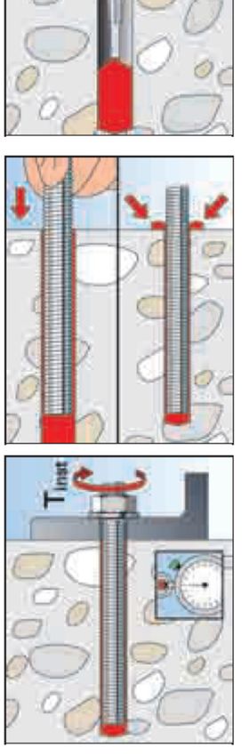
Surface Mount – to concrete using FH II Mechanical Anchor and Studding
1. For Cracked and Non-Cracked concrete.
2. Please refer to the technical manual for details on drill
depths and diameters.
3. Drill a suitable hole to suit the size of studding selected.
4. Thoroughly clean the hole using a hole brush and blower, or
similar.
5. Insert the FH II Socket into the Hole.
6. Tap the anchor into place and using the Setting tool set the
anchor in place.
7. Insert the threaded rod into the anchor and tighten to max
depth 25m into the anchor
8. Put the plate over the stud heads.
9. Tighten the nuts onto the threaded rod to the required
torque
10. Have the plate sealed by a trained roofing installer.
Roof Edge
I n s t a l l a t i o n M a n u a l
J u l y 2 0 2 1 v 1 . 119
Installation
Installation Procedure
Cast In
1. For Cracked and Non-Cracked concrete.
2. Tape over any holes such as the locking points (top and
bottom) and the main socket section
3. Place the socket into the form and secure if necessary.
4. Form the concrete
5. Remove the upper tape and insert the weather cap.
I n s t a l l a t i o n M a n u a l
J u l y 2 0 2 1 v 1 . 1NETHERLANDS UK
Azewijnseweg 12 SF Riverside, Mountbatten Way
4214 KC Congleton
Vuren Cheshire, CW12 1DY
t | + 31(0) 183 820 280 t | + 44 (0) 1260 217 437
info@bettersafeinternational.com
www. bettersafeinternational.com
I n s t a l l a t i o n M a n u a l
J u l y 2 0 2 1 v 1 . 1You can also read