Sensitivity enhanced roll-angle sensor by means of a quarter-waveplate
←
→
Page content transcription
If your browser does not render page correctly, please read the page content below
tm – Technisches Messen 2021; 88(S1): S48–S52

Chia-Wei Chen*, Matthias Hartrumpf, Thomas Längle, and Jürgen Beyerer

Sensitivity enhanced roll-angle sensor by means
of a quarter-waveplate
Empfindlichkeitssteigernder Rollwinkelsensor mittels einer Viertelwellenplatte

DOI 10.1515/teme-2021-0069 sert die Empfindlichkeit und reduziert die Komplexität
 der Systemausrichtung mithilfe einer festen Viertelwellen-
Abstract: Attitude metrology (roll, pitch, and yaw) plays
 platte. Der vorgeschlagene Sensor bietet einen einfachen
an important role in many different fields. Roll angle is con-
 Aufbau zum Messen von Rollwinkeln mit einer hohen
sidered the most difficult measurement quantity in angular
 Auflösung von 0.006∘ und einem langen eindeutigen Mess-
displacements compared to pitch and yaw angles because
 bereich von 180∘ .
the rotation axis of the roll angle is parallel to the probe
beam. In this work, a sensitivity enhanced roll-angle sen- Schlüsselwörter: Rollwinkel, Winkelsensor, Polarisations-
sor is presented. The principle is based on the polarization sensor
change of a sensing unit (quarter-waveplate). The polariza-
tion model is analyzed by Mueller matrix formalism. The
Stokes parameters are detected by a Stokes polarimeter.
 1 Introduction
The novel coaxial design improves the sensitivity and re-
 Attitude metrology (roll, pitch, and yaw) plays an impor-
duce the complexity of optical system alignment by means
 tant role in many different fields, e.g., precision machinery
of a fixed quarter-waveplate. The proposed sensor provides
 [2], remote sensing [4] and space docking [17]. Compared
a simple setup to measure roll angles with a high sensitiv-
 to pitch and yaw angles, roll angle is considered the most
ity of 0.006∘ and a long unambiguous measurement range
 difficult measurement quantity in angular displacements
of 180∘ .
 because the rotation axis of the roll angle is parallel to the
Keywords: Roll angle, angle sensor, polarization sensor probe beam[15]. State-of-the-art technologies for roll-angle
 measurements are autocollimator [10], optoelectronic level
Zusammenfassung: Winkelmessungen (Rollen, Neigen
 [5], relative position shift of two parallel laser beams [2],
und Gieren) spielen in vielen verschiedenen Bereichen eine
 rotary encoder [16] and variation of polarization states
wichtige Rolle. Der Rollwinkel wird als die schwierigste
 [14]. Except for the last two methods, the measurement
Messgröße bei Winkelverschiebungen im Vergleich zu Nick-
 range of other methods is limited to few degrees or few
und Gierwinkeln angesehen, da die Rotationsachse des
 arcminutes [16]. Rotary encoders can only be applied when
Rollwinkels parallel zum Sondenstrahl verläuft. In dieser
 the measured object has a fixed axis of rotation. In other
Arbeit wird ein sensitivitätsverbesserter Rollwinkelsensor
 words, the distance between the optical head and the
vorgestellt. Das Prinzip basiert auf der Polarisationsände-
 disk scale is fixed. This constraint limits the feasibility
rung der Sensoreinheit (Viertelwellenplatte). Das Polari-
 for long-range measurements, e.g., accuracy calibration of
sationsmodell wird durch den Müller-Matrixformalismus
 precision machines and orientation tracking for robots. In
analysiert. Die Stokes-Vektoren werden von einem Stokes-
 general, the polarization-based measurement can provide
Polarimeter erfasst. Das neuartige koaxiale Design verbes-
 a large measuring range with a high resolution and the
 distance between the sensing unit and the detector can
*Corresponding author: Chia-Wei Chen, Vision and Fusion be flexible. Li et al. proposed a compact optical roll-angle
Laboratory (IES), Karlsruhe Institute of Technology (KIT), and sensor in a range of ±30∘ with a resolution of 0.01∘ by
Fraunhofer Institute of Optronics, System Technologies and
 using a Faraday rotator as a sensing unit [12]. Kuang et
Image Exploitation IOSB, E-Mail: chia-wei.chen@kit.edu;
chia-wei.chen@iosb.fraunhofer.de al. measured the roll angle in a range of ±30∘ with a
Matthias Hartrumpf, Thomas Längle, Fraunhofer Institute of resolution of 0.04 arcminutes [11]. Shi and Guo introduced
Optronics, System Technologies and Image Exploitation IOSB a new concept for roll-angle measurements by using a
Jürgen Beyerer, Vision and Fusion Laboratory (IES), Karlsruhe half-waveplate and a right angle prism[15]. Gillmer et al.
Institute of Technology (KIT), and Fraunhofer Institute of Op-
 demonstrated a roll sensor in a working range of 43∘ with
tronics, System Technologies and Image Exploitation IOSB
C.-W. Chen et al., Sensitivity enhanced roll-angle sensor S49

a resolution of 0.002∘ by measuring the azimuthal angle Equation 2 shows the polarization model of the measure-
of a half-waveplate with modulated signals [7]. Chen et al. ment described by Stokes vectors and Mueller matrices,
presented an absolute roll-angle sensor using a retarder as where MNPBS , MQWP and MMirror are the Muller ma-
a sensing unit in a range of 180∘ with a resolution of 0.01∘ trices of the NPBS, the QWP and the mirror, and r, t,
[4]. In this paper, we propose a new roll-angle sensor based and denote the reflection and the transmission of the
on the concept of Shi and Guo[15]. We replace the right NPBS and the fast-axis orientation angle and the retar-
angle prism with a quarter-waveplate (QWP) and a plain dance of the QWP, respectively. The full form of MQWP
mirror to achieve a coaxial design. The roll angle is ob- is shown in Eq. 3. If every element is ideal, MrNPBS and
tained by measuring the change of the polarization states MMirror are diagonal matrices, where the diagonal ele-
of a sensing unit (QWP). The feature of the proposed ments are 1, 1, −1, and −1. MrNPBS is a diagonal matrix
sensor is the high sensitivity of the roll-angle measurement with diagonal elements 1, 1, 1, and 1. For simplicity, we
 ]︀T
 set 1 = 2 = 90∘ , 2 = 0∘ and Sin = 1 1 0 0 .
 [︀
with a large measurement range.
 Then, the measurement result can be expressed as:
 ⎡ ⎤ ⎡ ⎤
 0 1
2 Measurement principle ⎢ 1 ⎥ ⎢ 1 (3 + cos 8 1 ) ⎥
 ⎥ ⎢ 4
 Sout ⎣ 2 ⎦ = ⎣− sin2 2 1 sin 4 1 ⎦ ,
 =⎢ (4)
 ⎥

 3 − cos 2 1 sin 4 1
 NPBS QWP2
 where 1 can be seen as the roll angle.
 Sin Figure 2 presents simulated Stokes parameters for the
 roll angle from 0∘ to 180∘ . It is obvious that the periods
 ∘ ∘ ∘
 Linearly polarized Sout QWP1 Mirror of 1 , 2 , 3 are 45 , 90 and 180 , separately. The Stokes
 light source polarimeter can measure full Stokes parameters. There-
 fore, the roll angle can be solved by 1 , 2 or 3 in Eq. 4
 analytically. For better visualization of the evolution of
 Stokes polarimeter Sout , Sout are mapped to the Poincaré sphere as shown
 in Fig. 3. Compared to the work from Chen et al. [4], the
Fig. 1: The schematic of the roll-angle sensor, where Sin and period of 1 is reduced from 90∘ to 45∘ . In theory, the
Sout are the Stokes vectors of the linear polarized light source
 resolution could be enhanced twice. Since 1 is a cosine
and the return beam reflected by the NPBS.
 wave, it is feasible to use commercial encoders to inter-
 polate the signal. If 1 can be interpolated with a 14-bit
 Figure 1 shows the schematic of the proposed roll- encoder, the resolution can be achieved to 0.003∘ and the
angle sensor. The linearly polarized light passed through unambiguous range is 180∘ . Therefore, this configuration
a non-polarizing beamsplitter (NPBS), two quarter- has a high sensitivity and a large measurement range for
waveplates (QWP1 and QWP2), and the returned beam roll-angle measurements.
was reflected by the NPBS and ultimately received by
a Stokes polarimeter. In the system, QWP1 is a sensing
unit for the roll angle and the other components are fixed.
The polarization effect of optical elements or interaction
 3 Experiment setup
at boundaries can be described by Stokes vectors and
 Figure 4 shows the prototype of the roll-angle sensor
Mueller matrices [6]. Stoke vectors S describe the polar-
 which consists of a laser with a wavelength of 638 nm
ization state of light beams. Mueller matrices M represent
 from Integrated Optics, a linear polarizer (PGT 3.05,
the characteristics of the altering of Stokes vectors when
 B. halle Nachfl.GmbH), a NPBS (CM1-BP145B1, Thor-
light interacts with matter.
 labs, Inc.) two QWPs (WPQ10ME-633, Thorlabs, Inc.),
 a silver mirror and a Stokes polarimeter (PAX1000VIS,
 ⎡ ⎤ ⎡ ⎤
 0 11 12 13 14 Thorlabs, Inc.). QWP1 is mounted on a piezo rotation
 ⎢ 1 ⎥ ⎢ 21 22 23 24 ⎥ stage (M-660.55, Physik Instrumente GmbH). Compared
 S=⎢ ⎣ 2 ⎦ , M = ⎣ 31 32 33 34 ⎦ . (1) to polarizing beamsplitters, the NPBS has strong polar-
 ⎥ ⎢ ⎥

 3 41 42 43 44 ization distortions [9, 13, 18]. The wavelength mismatch
 between the laser and the QWPs also induces retardance
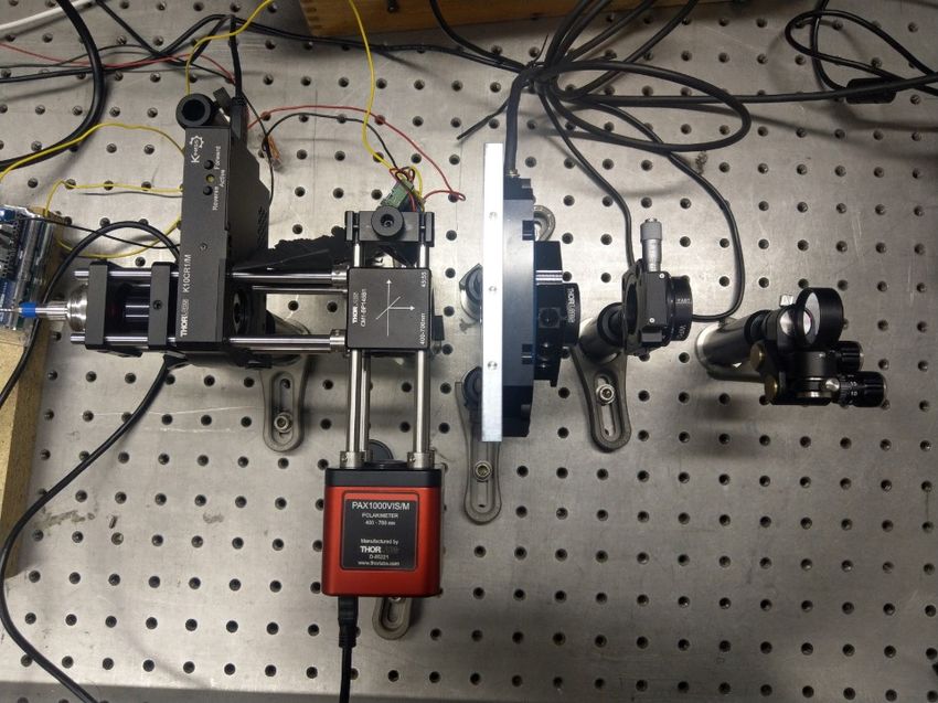
S50 C.-W. Chen et al., Sensitivity enhanced roll-angle sensor

 Sout = MrNPBS MQWP1 (− 1 , 1 )MQWP2 (− 2 , 2 )MMirror MQWP2 ( 2 , 2 )MQWP1 ( 1 , 1 )MtNPBS Sin . (2)

 ⎡ ⎤
 1 0 0 0
 ⎢0 cos2 2 + sin2 2 cos (1 − cos ) sin 2 cos 2 − sin 2 sin ⎥
 MQWP ( , ) = ⎢ ⎥. (3)
 ⎣0 (1 − cos ) sin 2 cos 2 sin2 2 + cos2 2 cos cos 2 sin ⎦
 0 sin 2 sin − cos 2 sin cos

 deviation. Therefore, these components in the prototype
 1
 should be carefully calibrated in order to obtain accurate
 0.8
 results.
 Normalized Stokes parameters

 0.6
 In this experiment, a Mueller-matrix ellipsometer is
 0.4
 applied to measure Mueller matrices of all the polarization
 0.2 elements. The Mueller-matrix ellipsometer can be easily
 0 integrated into this prototype. The details of the Mueller
 -0.2 matrices measurements and the calibration method of the
 -0.4 NPBS can be found in [3]. After calibration, we obtained
 -0.6 s
 that the retardance of the QWP1 ( 1 ) is 91.35∘ . The
 1
 s2 retardance ( 2 ) and the fast axis angle ( 2 ) of the QWP2
 -0.8
 s3
 are 90.95∘ and 0.04∘ . The measured Stokes vector after
 -1
 0 20 40 60 80 100 120 140 160 180 the NPBS and MrNPBS are [1, 1., −0.015, 0.]T and
 Roll angle (deg)

 −0.182 −0.002
 ⎡ ⎤
 1 0.0042
Fig. 2: Simulated Stokes parameters for the roll angle from 0∘ to
 ⎢−0.184 1.004 −0.002 −0.003⎥
180∘ . MNPBS =⎢ ⎥ . (5)
 ⎣−0.002 0. 0.957 0.272 ⎦
 0.003 −0.008 0.282 −0.939

 From the measurement data, it is clear that the QWPs and
 the NPBS are not perfect elements. Hence, careful calibra-
 tion of each optical element is necessary and important.

 1

 0.8
 θ = 112.5°
 θ = 157.5°
 0.6
 θ = 90°- 135°
 θ = 135°- 180°
 0.4

 0.2

 0 Laser LP NPBS QWP1 QWP2
 s3

 -0.2 θ = 0°, 45°, 90°, 135°, 180° Mirror
 -0.4
 θ = 45°- 90°
 -0.6 θ = 0°- 45° Stokes
 θ = 67.5°
 -0.8
 θ = 22.5° polarimeter
 -1
 -1 -0.8 -0.6 -0.4 -0.2 0 0.2 0.4 0.6 0.8 1
 Fig. 4: Photograph of the roll-angle sensor.
 s2

Fig. 3: Projection of the Poincaré sphere onto 2 − 3 plane for
the measured Stokes vector Sout .
C.-W. Chen et al., Sensitivity enhanced roll-angle sensor S51

4 Experimental result 0.03
 Measured angle by the proposed sensor
 Encoder readout of the piezo rotation stage
 0.025
In Eq. 4, the fast axis angle of QWP1 can be solved by
 1 , 2 or 3 analytically. Nevertheless, we used a numeri-
 0.02

 Roll angle (deg)
cal method to get higher accuracy [4]. The square error
function 2 can be written as 0.015

 3 (︁ )︁2
 0.01
 ∑︁
 2 = Exp
 − Calc
 ( 1 ) , (6)
 =1
 0.005

where the superscripts Exp and Calc indicate the experi-
mental and calculated quantities, respectively. Non-linear 0

optimization methods is applied to solve the fast axis 1 2 3 4 5 6
 Measurement times
angle of QWP1.
 We used the piezo rotation stage as an angle reference Fig. 6: Measured roll angles with steps of 0.006∘
since the stage has a high resolution (0.002∘ ) and good
repeatability (±0.004∘ ). Figure 5 shows the measurement
result of the roll-angle sensor. The sensing unit (QWP1) polarimeter. For the QWPs, the tilt angle and the incident
rotates from 0∘ to 180∘ with a step of 20∘ . Within the angle cause the deviation of the retardance [8]. From the
whole measuring range, the measurement errors are less specification of the polarimeter, the azimuth and ellipticity
than ±0.3∘ . accuracy are ±0.25∘ . For the worst case, the deviation
 of the Stokes elements is 0.009. Moreover, the surface
 roughness of the mirror and the beam deviation caused
 180 0.5 by the NPBS and the QWPs might have influences on the
 160 0.4 measured Stokes parameters.
 0.3
 Measurement error (deg)

 140
 Measured angle (deg)

 0.2
 120

 100
 0.1 5 Conclusion
 0
 80
 -0.1
 In this work, we proposed a novel roll-angle sensor with a
 60
 -0.2
 resolution of 0.006∘ and the measurement errors are less
 40
 than ±0.3∘ within an unambiguous measurement range
 -0.3
 of 180∘ . The principle is based on the polarization change
 20 Measured angle -0.4
 Measurement error of the sensing unit (QWP). The polarization change can
 -0.5
 0 20 40 60 80 100 120 140 160 180 be detected by a Stokes polarimeter. The proposed sensor
 Input roll angle (deg)
 uses a coaxial design which decreases the complexity of
Fig. 5: Results of the measured roll angles compared with the
 optical system alignment. The measurement resolution is
values of the piezo rotation stage. enhanced by using a fixed QWP and a mirror. The con-
 struction is simple and the sensor can be easily applied to
 existing measurement systems because of the non-contact
 We also conducted a sensitivity test for the proposed method and the compact design. For high-speed measure-
roll-angle sensor. The piezo rotation stage has a minimum ments, a division-of-amplitude photopolarimeter can be
incremental motion of 0.002∘ . In this test, we rotated used to achieve several s per Stokes vector [1, 19]. In the
the QWP1 five times with a step of 0.006∘ . The result is future, we plan to evaluate the uncertainty of the roll-angle
shown in Fig. 6. Because the stage is in open-loop opera- sensor and study the calibration and the stability of the
tion, the step size is not constant due to the mechanical system, especially for the Stokes polarimeter as the actual
influences, e.g., friction. It can be seen the result shows a limiting factor of roll-angle measurements. Moreover, the
high agreement with the rotation stage and the sensitivity sensor can be extended to 3-axis angle sensors by adding a
of the proposed roll-angle sensor is better than 0.006∘ . two-dimensional position sensitive detector [17] which can
 Several sources of error exist in the experiments, such
as the alignment of the QWPs and the accuracy of the
S52 C.-W. Chen et al., Sensitivity enhanced roll-angle sensor

be used for the orientation tracking. Further applications [12] S. Li, C. Yang, E. Zhang und G. Jin. Compact optical
will also be studied. roll-angle sensor with large measurement range and high
 sensitivity. Optics Letters, 30(3):242–244, 2005. ISSN
 1539-4794. 10.1364/OL.30.000242. URL https://www.
 osapublishing.org/viewmedia.cfm?uri=ol-30-3-242&seq=0.
 [13] Y.-C. Liu, Y.-L. Lo und C.-C. Liao. Opt. Commun., 361:153–
 161, 2016. ISSN 00304018. 10.1016/j.optcom.2015.09.099.
 [14] Z. Liu, D. Lin, H. Jiang und C. Yin. Roll angle interferometer
References by means of wave plates. Sensors and Actuators A: Physical,
 104(2):127–131, 2003. ISSN 0924-4247. 10.1016/S0924-
 4247(03)00003-7.
[1] R. Azzam. Division-of-amplitude photopolarimeter (doap) for [15] E. Shi, J. Guo, Z. Jia und Y. Huang. Theoretic study on new
 the simultaneous measurement of all four stokes parameters method for roll angle measurement of machines. In 2008
 of light. Optica Acta: International Journal of Optics, 29(5): IEEE International Conference on Automation and Logistics,
 685–689, 1982. ISSN 0030-3909. 10.1080/713820903. S. 2722–2726. IEEE, 92008. ISBN 978-1-4244-2502-0.
[2] Y. Cai, B. Yang und K.-C. Fan. Robust roll angular error 10.1109/ICAL.2008.4636635.
 measurement system for precision machines. Optics express, [16] Y. Shimizu, L. C. Chen, D. W. Kim, X. Chen, X. Li und
 27(6):8027–8036, 2019. H. Matsukuma. An insight on optical metrology in manufac-
[3] C.-W. Chen, M. Hartrumpf, T. Längle und J. Beyerer. turing. Measurement Science and Technology, 2020. ISSN
 Retroreflex ellipsometry for isotropic substrates with non- 0957-0233. 10.1088/1361-6501/abc578.
 planar surfaces. Journal of Vacuum Science & Technology B, [17] R. Treichel, R. Sesselmann und J. Krieger. Optical sensor
 Nanotechnology and Microelectronics: Materials, Processing, for measurement of roll + pitch + yaw angles over large dis-
 Measurement, and Phenomena, 38(1):014005, 2020. ISSN tances with high accuracy. S. 199–207. International Society
 2166-2746. 10.1116/1.5121854. for Optics and Photonics, 1999. 10.1117/12.364285. URL
[4] X. Chen, J. Liao, H. Gu, C. Zhang, H. Jiang und S. Liu. https://www.spiedigitallibrary.org/conference-proceedings-
 Remote absolute roll-angle measurement in range of 180° of-spie/3824/0000/Optical-sensor-for-measurement-of-roll--
 based on polarization modulation. Nanomanufacturing and pitch--yaw/10.1117/12.364285.full.
 Metrology, 3(3):228–235, 2020. 10.1007/s41871-020-00069- [18] S. Zhang, H. Gu, J. Liu, H. Jiang, X. Chen, C. Zhang und
 0. S. Liu. J. Opt-UK, 20(12):125606, 2018.
[5] K.-C. Fan, T.-H. Wang, S.-Y. Lin und Y.-C. Liu. Design of [19] S. Zhang, H. Jiang, H. Gu, X. Chen und S. Liu. High-speed
 a dual-axis optoelectronic level for precision angle measure- mueller matrix ellipsometer with microsecond temporal
 ments. Measurement Science and Technology, 22(5):055302, resolution. Optics express, 28(8):10873–10887, 2020.
 2011.
[6] H. Fujiwara. Spectroscopic ellipsometry: Principles
 and applications. John Wiley & Sons, Chichester, Eng-
 land and Hoboken, NJ, 2007. ISBN 9780470060186.
 10.1002/9780470060193.
[7] S. R. Gillmer, X. Yu, C. Wang und J. D. Ellis. Robust high-
 dynamic-range optical roll sensing. Optics Letters, 40(11):
 2497–2500, 2015. ISSN 1539-4794. 10.1364/OL.40.002497.
[8] H. Gu, X. Chen, C. Zhang, H. Jiang und S. Liu. Study of the
 retardance of a birefringent waveplate at tilt incidence by
 mueller matrix ellipsometer. Journal of Optics, 20(1):015401,
 2017.
[9] B. Johs und P. He. Substrate wobble compensation for
 in situ spectroscopic ellipsometry measurements. Jour-
 nal of Vacuum Science & Technology B, Nanotechnology
 and Microelectronics: Materials, Processing, Measurement,
 and Phenomena, 29(3):03C111, 2011. ISSN 2166-2746.
 10.1116/1.3555332.
[10] O. Kranz, R. D. Geckeler, A. Just und M. Krause. Modelling
 ptb’s spatial angle autocollimator calibrator. In Modeling
 Aspects in Optical Metrology IV, Band 8789, S. 87890D.
 International Society for Optics and Photonics, 2013.
[11] C. Kuang, Q. Feng, B. Zhang, Z. Zhang und S. Chen. Mea-
 surement method of the roll angle. S. 61502F. International
 Society for Optics and Photonics, 2006. 10.1117/12.676891.
 URL https://www.spiedigitallibrary.org/conference-
 proceedings-of-spie/6150/61502F/Measurement-method-of-
 the-roll-angle/10.1117/12.676891.full.
You can also read