SimpleBGC 32bit 3-Axis Software User Manual - Board all 32bit versions Firmware v. 2.63 and above GUI v. 2.63 and above Last edit: 1. Sep. 2018 ...
←
→
Page content transcription
If your browser does not render page correctly, please read the page content below
SimpleBGC 32bit 3-Axis
        Software User Manual

Board all 32bit versions
Firmware v. 2.63 and above
GUI v. 2.63 and above
Last edit: 1. Sep. 2018

© Basecamelectronics® 2013-2018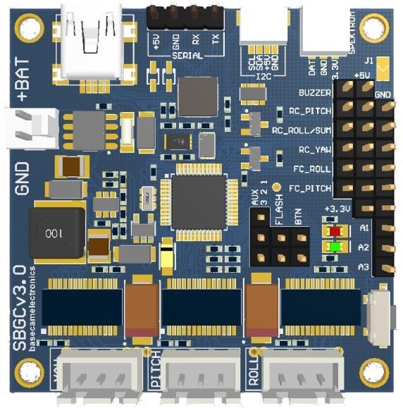
CONTENTS

                1. Overview.............................................................................................3
                2. Step-by-step setup sequence........................................................10
                3. The Basecam GUI overview............................................................14
                4. Hardware settings...........................................................................17
                5. Stabilization settings.....................................................................29
                6. PID auto-tuning...............................................................................34
                7. RC Settings.......................................................................................36
                8. Follow Mode Settings.....................................................................42
                9. Service Settings...............................................................................45
                10. System Monitoring.......................................................................54
                11. Adjustable Variables.....................................................................55
                12. Firmware update...........................................................................61
                13. System Analysis Tool....................................................................65
                14. User-written scripts......................................................................70
                15. Encoders........................................................................................71
                16. Magnetometer sensor..................................................................73
                17. Bluetooth module configuration.................................................77
                18. Using an external IMU sensor to improve the precision of
                stabilization.........................................................................................79
                19. Support of the MavLink protocol for FC connection.................85
                20. Correction of the motor's "cogging" effect.................................89
                21. Using 4th motor for a gimbal frame positioning......................92
                22. Possible problems and solutions................................................96
                23. Credits............................................................................................97

© Basecam Electronics® 2013-2018                                                                                            2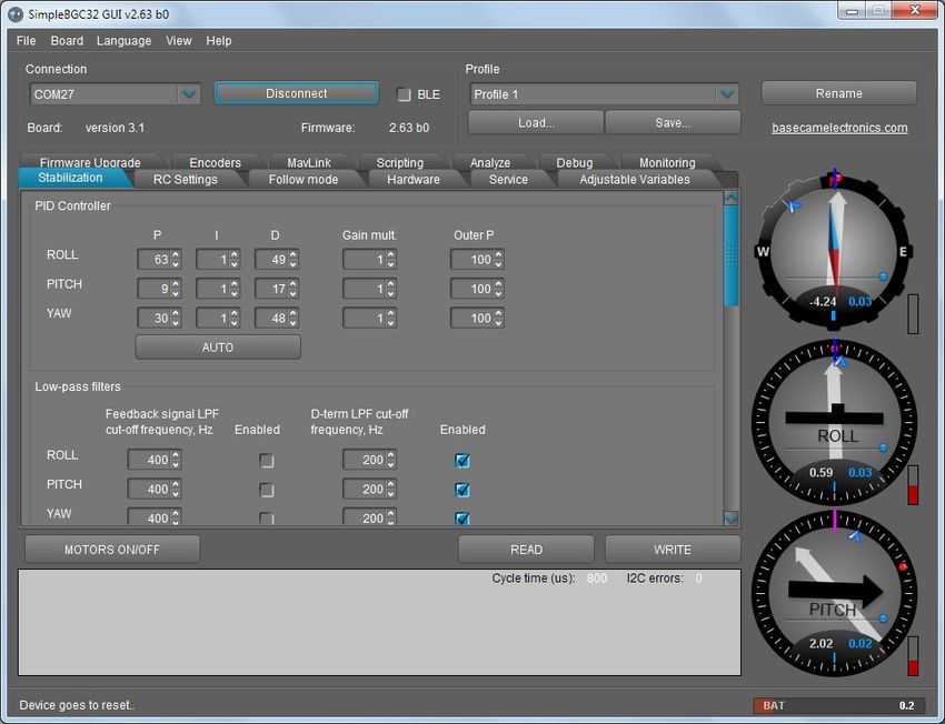
1. Overview

   1. Overview
   This manual provides directions on how to connect, adjust and calibrate the SimpleBGC 32bit 3-Axis
   controller board by Basecam Electronics. To begin using the board the following are the components that
   are necessary to assemble:
       • The controller board and additionally either one or two IMU units.
       • A USB connection to the board or an optional Bluetooth converter (a standard TTL interface
           Bluetooth module readily available in the market).
       • A computer to make and write settings to the controller via Basecam's software.
       • And the Basecam software which runs on Windows, MacOS and Linux. The software is downloaded
           from the Basecam website. Note that the GUI software version should match (or be greater than)
           the firmware version deployed on the board.

   Also needed ultimately is a gimbal with 1, 2 or 3 brushless direct-driven motors, that is well balanced in
   each dimension about its center point. The objective for gimbal design is that the center of effort be a fixed
   unmoving point- irrespective of the position of the gimbals arms and that the camera (the stabilized device)
   be mass-centered at that point. Gimbal construction should be very stiff – the only motion that is
   acceptable, is a rotation of motor's shaft. Flexible arms or shaft bearing end play may seriously impact the
   quality of stabilization.

   Additional optional components such as switches, joystick operation and interfaces to remote control
   devices (PWM, Sum PPM, or S.Bus from a standard RC receiver) are described in detail farther on.

   SimpleBGC32 actively compensates for undesirable movement in the stabilized portion of the gimbal
   (which mounts a camera or other device) that requires precise positioning irrespective of movement in the
   surrounding frame of reference. Stabilizing is accomplished by driving gimbal motors in response to
   reception of a signal from the gyroscopic sensor(s). The primary gyroscopic sensor is mounted on the
   camera to register precisely any rotation (to be compensated). Either one or two sensors can be used - a
   Primary IMU (sensor) which is attached to the camera and optionally a Frame IMU (sensor) which is
   attached to the frame in one of two positions). When two sensors are attached, a data from both is used by
   the controller board simultaneously for more precise system stabilization. To improve system performance,
   optional rotary position sensor (encoder) may be installed on each motor. More info about advantages and
   requirements of using encoders, you can find on the page http://www.basecamelectronics.com/encoders/

   SimpleBGC32 implements a simple Serial API protocol, that allows any external device to communicate
   with the gimbal controller and introduce a great possibility to apply stabilization solutions in many areas.
   Serial API specification and examples can be found at the page http://www.basecamelectronics.com/serialapi/

   © Basecamelectronics® 2013-2018                                                                         3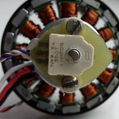
1. Overview

   Introduction
   The system controller board and software are designed and licensed by Basecam Electronics. You can
   purchase our controller directly from us at our web store (http://www.basecamelectronics.ru/store/) or you may
   purchase one manufactured under contract by one of our partners. The list of our official partners is
   available on our web site http://www.basecamelectronics.ru/wheretobuy/. Different manufacturers may alter the
   controller slightly (for example, by adding an integrated Bluetooth component or by changing its size etc.).
   In either case note the board version and relevant data published on the corresponding manufacturer's web
   site.

   Some of our partners make just the boards available and others make finished gimbal products with pre-
   installed controllers (http://www.basecamelectronics.com/readytouse/). Gimbals are also available (both with and
   without motors) but without electronic stabilization system. In these case you will need to purchase a
   controller (from us as noted above or from one of our partners providing just the boards) and install it
   yourself. If you decide to assemble a stabilization system yourself, please visit our forum where you can
   find the necessary information (http://forum.basecamelectronics.com).

   We describe in this manual both the controller board itself as well as the multi-platform (software)
   application for its adjustment. We call the software application (the) Basecam GUI. As noted it may be
   downloaded from our website and also as noted above it is necessary to get the version of it that is
   associated with the firmware version that is installed on the board (the versions should match).

   The Basecam GUI software uses the Java runtime environment and a virtual COM port to aid in portability
   to other systems. Depending on the platform you may need to issue some commands to enable the port,
   and (on some platforms) it may be necessary to install a serial driver. Once running and connected the GUI
   looks and runs the same on all platforms. Note that when Bluetooth is employed as the serial bridge
   (rather than plugging the board into a computer with a USB cable) that it may be necessary to configure the
   bluetooth device. It may be done from an external software, or using our GUI ("Board" – "Configure
   bluetooth" utility). See below for more details.

   © Basecamelectronics® 2013-2018                                                                            4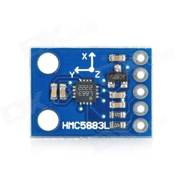
1. Overview

   Basic connections
   The connection scheme for the basic controller board is shown in figure 1:

                                                                      Battery 8-25V

                YAW motor                                                                                  USB to PC

               ROLL motor

                                                                                                           I2C to IMU
               PITCH motor

                                               Menu                       RC
                                               button                  receiver
                                                      Fig.1 Basic connections

       1. The USB port is used to connect the SimpleBGC 32bit stabilization board to PC.
       2. Gyroscopic sensor(s) (IMU's) are connected to I2C slot. When there is a second IMU their outputs are
          combined with an Y-cable and in either case a single connection is made to the port as shown.
       3. Each motor is connected to the corresponding motor output. If any output is not used, disable it in
          the GUI. Motors are configured in the "Hardware" tab.
          NOTE: It is advisable to pull each motor cable through (and make at least one loop around) a ferrite ring to avoid
          high frequency interference from affecting the IMU sensors and other electronic devices (both on and connected to
          the board).
       4. The controller board is equipped with a power cable for connection to a battery. Observe polarity at
          all times, do not make an incorrect connection! Even a brief (instantaneous) incorrect connection
          may damage (or destroy) the board.

   When handling batteries, never cross terminals, even momentarily. Particularly when handling lithium batteries,
   accidentally locking terminals may very definitely cause a fire or explosion! Use great care particularly when cutting and
   soldering battery leads to prevent any contact of opposite poles in a closed circuit.

            NOTE: Maximum allowed battery voltage is defined for each controller individually in its specifications. If you use a
            lithium-polymer battery (LiPo), and it's marked 3S, that stands for the quantity of (standard 3.6v nominal) cells in a
            given battery. The maximum voltage of a cell is 4.2V when fully charged. It means that a fully charged 3S LiPo is
            equal to 12.6V and 5S LiPo is equal to 21V. Observe all warning indications regarding safe handling of lithium
   © Basecamelectronics® 2013-2018                                                                                            5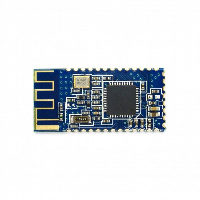
1. Overview

           polymer batteries. Remember that LiPoly batteries use only chargers specifically designed for this chemistry. Never
           connect a LiPoly battery to a charger not intended for this battery chemistry.

   A detailed description of a controller connection within a complete stabilization system can be found in the
   detailed connection scheme.

   GUI installation
   First you need to download the latest version of the GUI application from our web site
   (http://www.basecamelectronics.com/downloads/32bit/). Unpack it in any folder. To start the application you need
   to have the Java Runtime Environment (managed by Oracle Inc) installed in your system. To obtain the
   product for your system see http://www.java.com. For each of the systems, in the unpack directory:

   To run the Basecam GUI for Windows:
       •    run SimpleBGC_GUI.exe

   To run the Basecam GUI for MAC OS:
       • run SimpleBGC_GUI.jar

           ATTENTION: The Basecam GUI uses a virtual COM port. To get that to work (on MacOS) a lock file will need to be
           created (it uses the lock file to control flow back and forth through the virtual COM port). Due to security constraints,
           you need to create the lock file yourself. Start terminal (Terminal is an application in the Utilities directory).

           Into terminal- type- with great care if you are less experienced:

                    Make folder "/var/lock" by command:

               1. sudo mkdir /var/lock

                    Change permissions by command:

               2. sudo chmod 777 /var/lock

                    Either allow your system to run non-signed applications by setting this in:
                    System Preferences > Security & Privacy > General > Allow Applications downloaded from: Anywhere
                    Or you can allow just this one app to run by answering Open when prompted by the system dialog. In this
                    case, as in the other navigate to the unpack directory and

               3. double click (to run) SimpleBGC_GUI.jar

   To run the Basecam GUI for LINUX:
       • run run.sh

   Running GUI on high-DPI displays
   If GUI window appears abnormally small – you have a high-DPI display or font settings > 100% is not
   applied – you may need to perform additional actions to make it looking better.
   Option 1: Download and install Java 9 JRE from Oracle. Allow installer to remove old versions.

   © Basecamelectronics® 2013-2018                                                                                           6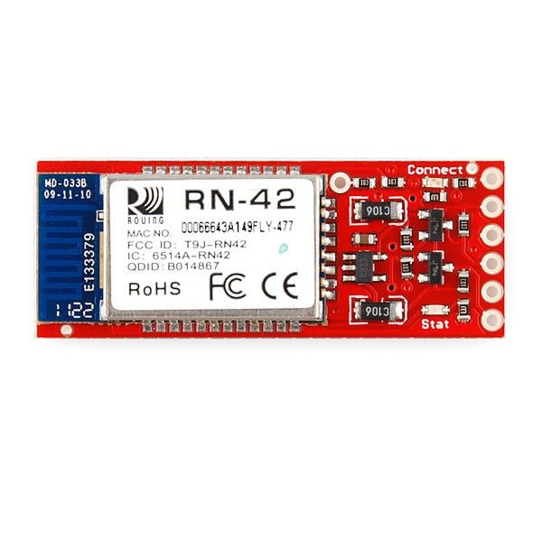
1. Overview

   At the moment of writing this article, Java 9 download was located here:
   http://www.oracle.com/technetwork/java/javase/downloads/jre9-downloads-3848532.html
            NOTE: If you have other Java applications in your system that are not compatible with the Java 9, you can keep old
            JRE, but you have to manually specify the path to the JRE 9 in the "run_console.bat" file and start GUI using it.

   Option 2: In Windows 10, you can change the "compatibility" property of the Java executable. Note that it
   affects all Java-based applications.
          • Find java.exe in the JRE or JDK installation folder
          • Right click -> "Properties"
          • Go to the "Compatibility" tab
          • Check "Override high DPI scaling behavior"
          • Set "Scaling performed by" to "System"
          • Repeat the same for the javaw.exe

   Connection to computer
   The controller has either a Mini- or Micro-USB (depending on the version). To connect the board to the
   computer you will need to install a driver to first establish a connection. If the driver is not installed
   automatically, you can download it — for all operating systems - follow the link:
   http://www.silabs.com/products/mcu/pages/usbtouartbridgevcpdrivers.aspx

            NOTE: For the "Tiny Rev. A” version the driver for Windows can be downloaded here
            http://www.st.com/web/en/catalog/tools/PF257938. This is latest official driver from ST company. But it was reported,
            that it does not work under Windows 8. In this case, try previous version, that should work:
            http://www.basecamelectronics.com/files/drivers/VCP_Setup.zip. Normally, new COM port should appear in the Device
            Manager, under "COM and LPT Ports". If it's not true and new device is located under "Universal serial Bus devices" as
            "Unknown device", you need to upgrade driver manually, selecting "STMicroelectronics Virtual COM port" driver.

            WARNING: the version 6.7.4 of the CP210x driver may work improperly with the older versions of GUI (all versions
            prior to 2.63b0), causing a big delays in serial communication. You can downgrade to previous version of a driver (can
            be downloaded by the link https://www.basecamelectronics.com/files/drivers/CP210x_Windows_Drivers_6_7_2.zip), or
            update GUI to the latest version where this problem is solved.

   After you have installed the driver and connected the controller with USB you will see a new virtual COM
   port in the GUI in the Connection dropbox. Its name should appear upon connection.

   You can connect the controller to a computer and supply power from a battery simultaneously. Again be
   careful and observe polarity of battery terminals because when a USB connection is established, the in-built
   reverse polarity protection is off (some versions are not equipped with such protection).

   Wireless connection
   To connect controller to the GUI, you can also use a wireless connection through a Bluetooth-to-Serial
   converter on the board side and USB-Bluetooth adapter from the PC side (your PC may of course have built
   in Bluetooth). On the board side working converters are, for example: HC-05, HC-06, Sparkfun BlueSMiRF
   and other Bluetooth 2.1-compatible modules (BLE modules like HM-10, HM-11 are not supported!). The
   converter should have at least 4 outputs: Gnd, +5V, Rx, Tx and it attaches to the controller at the
   corresponding slot (located near the USB port) marked with UART (or Serial). Regardless of the boards
   labeling the board's pins are TTL logic- not RS232.

   Bluetooth module connection is shown in the Appendix B.
   © Basecamelectronics® 2013-2018                                                                                        7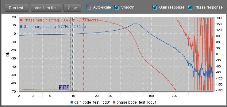
1. Overview

           NOTE: Bluetooth module should be set for baud=115200 and parity=None or Even. Under None the board can be
           connected to the GUI with parity set to either. However to update the board firmware through the Bluetooth
           connection parity on the device must be set to Even. Working with different baud rates is possible (just change
           parameter Hardware->Serial Port Speed to match module's baud rate) but some operations like realtime data
           monitoring, will be slowed down, so better to configure bluetooth module. To change Bluetooth module settings, see
           its manual. Starting from firmware version 2.55, there is a tool under “Board” →“Configure bluetooth...” that can
           configure most popular bluetooth adapters (see Bluetooth module configuration).

   Serial-over-Network (UDP) and TCP/IP connection options
   These types of connection allows to configure SimpleBGC controller remotely, when it is physically
   connected by UART to another device, that can communicate with the GUI over network (Wi-Fi, Ethernet,
   Internet).
      •    UDP: Before connecting, you have to configure local port where GUI listens for incoming UDP
           messages, and remote host and port to send outgoing messages (optional). You can do it in the “File
           → Settings..” menu. If remote port and host is not specified, it will be obtained from the first
           incoming UDP message.
      •    TCP/IP: Use this type of connection to work with the WiFi-to-UART transparent bridge. In the
           settings you have to configure remote host and port. This information comes in a specification of
           particular device. For the "Basecam WiFi UART adapter", host is 192.168.4.1 and port is 23. Note
           that first you have to connect to WiFi spot manually using a wireless network manager of your PC.

   Running the application
      1. Attach USB cable (or, if connection over Bluetooth, pair the devices. Default password is 1234 or
         0000, generally).

      2. Run GUI, select COM port from the list in the left corner dropbox of the main window and press
         Connect.

      3. When the connection to the board is established all profiles will be read and downloaded and the
         GUI will display the current profile settings. You can read the board settings again any time by
         pressing the READ button.

      4. Make sure to have installed the latest version of firmware. To check: open "Upgrade" tab and press
         "Check update". Update if a new version is available. Note that after updating the firmware you will
         need to re-download the corresponding version of the GUI and revisit this connection scenario. See
         section "Firmware Update" for more detailed information.

      5. After you have finished editing parameters, press WRITE to save them to the persistent memory of
         the controller (EEPROM). Only the currently selected profile will be saved.

      6. In order to erase the settings of ALL profiles, general settings and calibration data, go to menu
         "Board" — "Erase EEPROM".

      7.   To switch over to the settings of another profile, choose the desired profile from the drop-down list
           labeled "Profile" (you can find it in the upper right corner of application's window). It is not required
           to read the parameters by pressing READ. You can save different settings in 5 different profiles.
           Profiles can be switched over through the GUI, by RC command, or by operating the menu button on
           the board. Note that some settings are shared among all profiles. These settings concern hardware
           component configuration in particular, as well as sensor orientation and configuration, and some
   © Basecamelectronics® 2013-2018                                                                                     8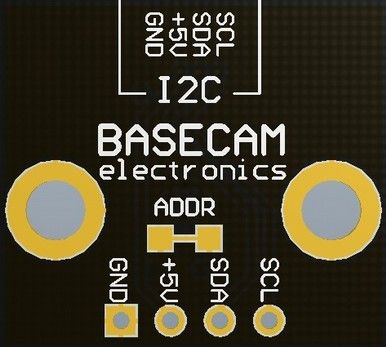
1. Overview

         others. Once you press WRITE button, currently edited profile will be written and becomes active in
         the board.

      8. You can assign random names to profiles. They will be saved on the board and will remain
         unchanged when you connect to the GUI from a different computer.

      9. When finished tuning, you can back-up your configuration several ways:

         ◦ Saving profile to a file: all parameters that are visible in the GUI (including hidden extended
           views), will be saved. But most of calibrations and scripts that are not loaded from the board on
           connection, do not go there.

         ◦ Saving EEPROM backup to a file: it contains all profiles and all calibrations, scripts and so on -
           the most complete configuration of the system.

         ◦ Saving EEPROM backup to a cloud: The same as saving EEPROM backup to a file, but you can
           access it over Internet. Also some market-available gimbals may have password-protected
           factory backup, that is impossible to overwrite and corrupt by the user.

   © Basecamelectronics® 2013-2018                                                                     9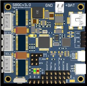
2. Step-by-step setup sequence
2. Step-by-step setup sequence
1. Adjusting the mechanics
Mount the camera on the gimbal's tray and balance the gimbal in all three axes. Stabilization quality
strongly depends on balance quality. To check your balance, take the (turned off) gimbal in your hands.
Make fast motions along all axes's - try to catch any resonance point by swinging the gimbal back and forth.
If it is hard to do - gimbal is balanced correctly.
NOTE: Good balance and low friction allows reduced power levels and still keeps good quality of stabilization.
If you rewound motors by yourself, it's recommended to check electrical resistance and connectivity of your
work! With motors removed from gimbal, connect them to controller and set parameters P=0, I=0.1, D=0 for
each axis and set enough POWER. Connect main power supply. Motors should spin smoothly, while rolling
the sensor. A little jitter is normal due to magnetic force between rotor and stator (“cogging” effect).
Pay great attention to sensor installation. Its axes must be aligned in parallel with the motors axes. Pay a
great attention to mechanical links: they must be rigid and backlash-free! Otherwise it may cause unstable
work in real conditions (frame vibrations, wind, etc), make system sensitive to impacts like steps.
2. Calibrating the sensor
Make sure IMU sensor is connected and recognized by the system: arrows on the gauge panel reflects a
rotation of a sensor.
Configure sensor orientation by setting Axis TOP and Axis RIGHT parameters. The fastest way is to use the
auto-detection utility: press AUTO button and follow the instructions (at first step, level sensor, then tilt it
on the right side). More details you can find in the Main IMU sensor section.
Calibrating Gyroscope
The Gyro sensor is calibrated every time you turn the controller on, and it takes about 4 seconds to
complete. Try to immobilize the camera sensor as hard as you can in first seconds after powering on while
signal LED is blinking. After powering on you have 1 seconds to freeze the gimbal before calibration starts.
If you activated option “Skip gyro calibration at startup” then the gyro is not calibrated each time and the
controller begins operating immediately after powering up. Be careful and recalibrate the gyro manually if
you notice anything wrong with IMU angles.
Calibrating Accelerometer
You must perform ACC calibration only once, but it's recommended to recalibrate it from time to time or
when the temperature significantly changes. Alternatively you can make a temperature calibration through
a full range of possible working temperatures (see Temperature Sensor Calibrating).
IMPORTANT: Before processing any kind of calibration, you need to reset old values by pressing "RESET" button in
the "IMU Calibration helper" window!
Simple calibration mode: set the sensor horizontally, and press CALIBRATE.ACC button in the GUI
(or the menu button, if it's assigned to “Calibrate ACC” action). The LED will blink for 2 seconds. Be
sure not to allow the sensor to move during calibration.
Advanced mode (recommended): to begin perform calibration in simple mode as above. Then turn
© Basecamelectronics® 2013-2018 102. Step-by-step setup sequence
sensor in order such that each side of the sensor looks up (6 positions at all, including base one). To
do this fix the sensor in each position, then press CALIB.ACC button in the GUI, and wait about 2-3
seconds (until the LED is stops flashing). You do not have to press the WRITE button at each step,
calibration data is written automatically (the data is written when the LED stops flashing for each
orientation performed).
To calibrate second sensor placed on the frame (if present), select it by the toggle buttons "Camera
IMU/Frame IMU". All raw sensor data, IMU angles and all calibration commands now relates to selected
sensor.
To simplify the 6-point calibration, use the "IMU Calibration helper" tool. It will show a currently
selected position and positions that are already calibrated.
NOTE: Precise accelerometer and gyro calibration is a very important for horizon holding during dynamic flying or
YAW rotation. it's advised to use a temperature compensation to keep precise operation in a wide range of
environmental temperatures (see Temperature Sensor Calibrating).
X
Z Z
X X
Z
Z X X
Z Z
X
3. Setting up basic parameters
For 1- or 2-axis system, disable unused motor outputs in the “Hardware” tab - “Motor outputs” group.
It is important to tell system how many active motors are connected, to select proper stabilization
algorithm.
Set POWER according to the motor configuration (see recommendations below)
Connect the main power supply. Motors should start to spin and if all is okay at this moment – will
stabilize camera. If motors spin randomly – check that sensor orientation is correct and motor
outputs are assigned to proper motors.
Auto-detect number of poles and motors direction in the "Hardware" – "Motor configuration" –
"AUTO". Do not proceed to next step until proper direction is detected! It is normal if number of
poles is detected with small error – in such case enter the correct value manually.
© Basecamelectronics® 2013-2018 112. Step-by-step setup sequence
Set parameters "Stabilization settings" – 'Gain multiplier' to 1.0, 'Outer P' to 100 for all axes (default
values).
Run auto-tuning for PID-controller, using default settings the first time.
Adjust PID controller settings if required. To check stabilization quality use the peak indicator in the
control panel (shown by the blue traces and blue numbers). Incline the frame by small angles and
try to minimize peak values by increasing P, I and D to its maximum. You may use gyro data from
the Monitoring tab to estimate stabilization quality too.
It is better to tune PID with the “Follow Mode” turned OFF for all axes.
Suggested algorithm for manual PID tuning:
1. Set I=0.01, P=10, D=10 for all axes. Gimbal should be stable at this moment. If not, decrease P
and D a bit. Than start to tune each axis sequentially:
2. Gradually increase P until motor starts to oscillate (you may knock the camera and see on the
gyro graph, how fast oscillation decays). Increase D a little – it should dampen oscillations, and
decay time decreases. The lower is decay time, the better.
3. Repeat step 2 until D reaches its maximum which is when high-frequency vibration begins to
appear (you may hear it or feel it in your hands and see noisy lines on the gyro graph). When
this begins current P and D values are at maximums for your setup. At this point decrease them
a little and go to step 4.
4. Increase I until low-frequency oscillation starts. Decrease I a little to keep gimbal stable. Now
you have found a maximum for all PID values for selected axis. Repeat from step 1 for other
axes.
5. When all axes are tuned in static, try to move gimbal's frame, emulating a real working
environment. You may notice that cross-influence of axes may make gimbal unstable. In this
case, decrease a little PID values from their maximum for axes that are animating.
Good tuning results in stabilization error of less than 1 degree when you slightly rock the gimbal's frame.
Further steps to improve the precision of stabilization:
• Connect, setup and calibrate second (frame) IMU (see Second IMU sensor).
4. Connecting and configuring RC
• Connect any free receiver's channel to the input labeled as “RC_PITCH “, observing the correct
polarity
In the RC Settings tab:
• Assign “RC_PITCH - PWM” input to PITCH axis.
• Leave all other axes and CMD channel as “no input”.
• For PITCH axis, set MIN.ANGLE=-90, MAX.ANGLE=90, ANGLE MODE is selected, LPF=5, SPEED=50.
• Connect the battery to the main controller and receiver, and check that RC_PITCH input receives
data in the “Monitoring” tab (slider should be blue filled and reflects stick movement).
Now you can control the camera from your RC transmitter, from -90 to 90 degrees. If you are not satisfied
with the speed of movement, adjust the SPEED setting. If stick need to be inverted, select the INVERSE
checkbox.
If your RC stick have neutral position, you can select the SPEED MODE that is commonly used for gimbal
© Basecamelectronics® 2013-2018 122. Step-by-step setup sequence
control.
Connect and tune remaining axes the same way, as required. You have 5 PWM inputs to assign to all axes
and to the “command” channel.
Analog joystick connection as well as other RC receiver protocols like S-bus, sum-PPM, Spektrum, are
discussed below in the "RC settings" section.
5. Testing gimbal in real conditions
For flight on multi-rotors, connect controller to the GUI and turn ON the vehicle's motors, holding it above
your head (and away from your face and hands). Check the vibrations on the camera by using the
Monitoring tab / ACC raw data. Try to decrease the level of vibrations using soft dampers on gimbal's mount,
balancing propellers, and so on.
NOTE: Brushless motors versus traditional servos provide faster reaction, but less torque. That's why it's hard for
them to fight against wind and air flows from props. If you are developing multi-rotor frame try to avoid these
influences (for example, lengthen arms a bit, or tilt motors away from the center or place the camera above props in
case of H-frame). Also bear in mind, when copter moves with high speed, an air flow is deflected and this affects the
gimbal as well.
© Basecamelectronics® 2013-2018 133. The Basecam GUI overview
3. The Basecam GUI overview
GUI Structure
The GUI contains different functional blocks:
1. A configuration block in the central part of the window, organized by ‘tab’:
Stabilization – settings related to stabilization algorithms, like PID gains, filters.
Hardware — Parameters related to hardware configuration of a system: motor configuration,
motor outputs, power level, IMU sensor position and calibrations and so on.
RC Settings – settings to control the gimbal roll/pitch/yaw orientation with RC inputs.
Service – service functions like menu button assignment, working positions and behavior at
startup, battery monitoring, sound.
Follow mode – settings related to special mode of the camera control when it follows the
frame.
Monitoring — real-time sensor data monitoring. This screen is extremely helpful in tuning your
gimbal performance.
Upgrade – lets you to check the version of firmware and upgrade if necessary.
© Basecamelectronics® 2013-2018 143. The Basecam GUI overview
Adjustable variables – you can change many system parameters on-the-fly by remote controller
or joystick
Analyze – tool that helps to fine tune system performance by scanning its frequency response.
Scripting – you can write user scenarios, load to EEPROM and execute by remote command.
Encoders – if gimbal is equipped by encoders, all parameters and calibrations are set there.
2. Connection — COM-port selection and connection status.
3. Profile — Profile selection, loading, re-naming, and saving.
4. Gauge Panel — graphic visualization of gimbal orientation angles in three axes.
Black arrows are displaying the angles, blue arrows are a 10x time magnification to provide higher
precision. Red marks show target angles that gimbal should keep.
Thin blue lines shows the maximum (peak) deflection from the central, neutral point.
Blue digits show peak deflection amplitude. Using these numbers, stabilization quality can be
estimated.
Vertical red bars to the right of the scales show actual power level from 0 to 100%.
Gray arrows shows the angle of a stator of each motor, if known.
5. READ, WRITE buttons are used to transfer setting from/to board.
6. MOTORS ON/OFF button is used to toggle motors state.
7. At the bottom of the screen, tips, status or error messages (in red color) are displayed . Overall
cycle time and I2C error count is also displayed.
8. Battery voltage indicator with warning sector.
HINT: If not all tabs or settings that are described in this manual, are displayed, check that the view level is set to
maximum: Menu – View – View level. Also note that the presence of some parameters depends on the hardware and
firmware versions.
File menu
• Save/Load profiles to a file – duplicates LOAD and SAVE buttons. Operates for currently selected
profile.
• Save profile using template... – sometimes it's necessary to prevent some parameters to be
included in the profile file. For example, you want to share some settings like RC or Follow
parameters between different systems, but do not want to overwrite other system-specific settings
like PIDs or hardware configuration. You can edit XML file (that profile actually is) manually,
removing unwanted parameters, but bad thing is that you have to do it each time you save profile
to a file. Alternative is to make it only once, than you can use this edited file as a template.
Templates are managed in the "File" – "Settings" dialog, where you can specify a path to a template,
then it will appear in the drop-down menu.
• Save all profiles to a file – the same as "Save profile", but saves all profiles to a single file. When it
is loaded back, you have to execute "Write all profiles to the board" under the "Board" menu.
• Settings.. - change settings related to the GUI application functionality.
© Basecamelectronics® 2013-2018 153. The Basecam GUI overview
Board menu
This menu encapsulates options related to controller.
• Read/Write settings - duplicates READ, WRITE buttons
• Execute action – execute command in the controller. The list and description of available actions
you can find in the "Service" section of this manual.
• Sensor – commands related to the IMU sensor calibration
• Configure bluetooth - makes an initial setup of the connected bluetooth module. See
corresponding section below.
• Erase EEPROM - completely reset controller by erasing EEPROM. All settings and calibrations will
be lost.
• Backup manager
It allows to make a backup of the EEPROM image, which holds the complete configuration of a
system (including all calibrations, scripts, adjustable variables and so on). It is safe to restore
EEPROM image made in older versions of firmware, in more recent versions – we maintain back-
compatibility. But restoring configuration made in recent version, from the older version, is not
possible.
There are several options available:
◦ Save/Restore to a file.
◦ Save/Restore to the server. Requires the Internet connection. You can save up to 3 user backups.
◦ Save/Restore as factory backup. It's password-protected, that makes it impossible to overwrite
or corrupt by the user.
• Backup/Restore IMU calibration – backup only calibration of the IMU sensor. You can use this
option to transfer calibration between two systems, when IMU was calibrated on one system but is
used on another.
Language menu
The GUI starts in the English version of the user interface. To change the interface language, choose the
one desired in the 'language' menu and restart the program.
View menu
• View level – you can select the level of complexity, that defines which settings will be allowed for
editing, and which will be hidden.
• Choose one of the themes - you can change a visual theme from the “View” menu. For example,
when using GUI outdoor, better to switch to one of the high-contrast themes.
• Full screen – go to full screen mode. But in this mode controls will not be resized.
Further in this manual each tab is described in details. At the end of this manual, you can find additional
step-by-step tuning recommendations.
© Basecamelectronics® 2013-2018 164. Hardware settings
4. Hardware settings
Motor configuration
POWER – maximum voltage supplied to the motors (0 - 255, where 255 means full battery voltage).
Choose this parameter according to your motor characteristics. Basic tuning:
◦ Motors should not get too hot! Motor temperatures of over 80С will cause permanent damage to
motor magnets.
◦ A Power value that is too low will not provide enough force for the motor to move the gimbal
and stabilize the camera adequately. A low power value will be most noticeable in windy
conditions, when the gimbal is not well balanced, or if the gimbal suffers from mechanical
friction. Slowly lower the Power parameter to find its optimal value. Find the lowest value that
still provides good stabilization and adequate holding torque.
◦ Raising the power equals raising the “P” and “D” value of PID settings. If you raise the POWER
value, you should re-tune your PID values as well.
BOOST POWER - additional power that will be add to the main power in case of error caused by the
lost synchronization of electrical and magnetic fields in a motor. It helps to restore sync and return
camera to the normal position.
Note: this parameter is ignored in the encoder firmware.
Overall current limit, mA (frw. ver. 2.66+ with encoders)– if this value is set to non-zero, controller
tries to estimate an overall current consumed by the motors, and limits it if exceeded. The given
limit is automatically distributed between all motors according to their demand. Use this option to
protect the battery in a case when it can provide enough current for a single motor, but all motors
being fully loaded, cause an overload. A resistance of each motor should be configured to let this
function to work. Limitations:
◦ The current is estimated according to the resistance of the motors and the sensed voltage of
the battery, and may differ from the actual current.
◦ Only the current through motors is limited. Current, consumed by the MCU (~100mA) and all
connected periphery, is not estimated and is not taken into account.
◦ If voltage of the motor driver circuit is not equal to the battery voltage (for example, the "Tiny"
controller has an internal DC/DC regulator), the estimated current will differ from actual
current.
Motor outputs — you can randomly assign hardware motor outputs for any stabilization axis, or
disable output that is not used, for 2- or 1-axis stabilizers. Options are:
◦ ROLL out, PITCH out, YAW out – motor ports labeled by corresponding names on the main
controller
◦ SBGC32_I2C_Drv#1..4 – external motor drivers, integrated directly into motors and controlled
by the I2C bus. More info: http://www.basecamelectronics.com/sbgc32_i2c_drv/
INVERT – reverse motor rotation direction. It's extremely important to choose the correct motor
rotation direction before tuning other parameters! To determine the correct direction, set the POWER
value big enough to rotate the camera without loosing synchronization. Level the camera tray
horizontally and click the AUTO button in the "Motor configuration" settings. The gimbal will make
small movement to determine its direction. Gimbal should not have any obstacles that prevent free
rotation at this range! Wait for the calibration procedure to complete for each motor. Finally, the
detected number of poles and inversion will be displayed in the GUI.
© Basecamelectronics® 2013-2018 174. Hardware settings
NUM.POLES – Number of motor poles. This value needs to be equal to the number of magnets in
your motor’s bell. During the “auto” calibration process described above, this value is automatically
detected. However, this value is sometimes not correctly determined during the “auto” calibration
process and will need to be verified and possibly corrected manually. Count your motor magnets
and enter this value if the value is not correct in the GUI.
PWM Frequency — sets the PWM frequency used to drive the gimbal motors. Two basic modes are
available : Low Frequency (in audible range) and High Frequency (~22kHz outside audible range).
Recommended mode is High. There is also third option Ultra-high (~30kHz) that may be selected
(but not recommended).
Magnetic linkage of a motor (ver. 2.60+) – this value depends only on Back-emf constant of a motor,
and does not depends on any other parameters of a system. Configuring it properly helps to
achieve better precision of stabilization and better control at high speeds of rotation of a frame or
a camera. Note that this compensation is applied only if a speed of a motor is known exactly (from
the 2nd IMU or encoders), and POWER is set below its maximum (255) to have a room for
compensation.
There is an auto-calibration routine. To make a calibration, do the following:
◦ Power ON motors and disable "Follow" mode. Gimbal should be configured and working, PIDs
should be tuned. 2nd IMU or encoders should be enabled and configured.
◦ Press AUTO button and tilt the frame with the moderate speed and amplitude by all axes
during 15 seconds (1-2 tilts per second with 20-40º amplitude). LED will flash and "calibration"
sound will be emitted.
◦ On complete, new values will be loaded into fields. Check that system operates without
problems. If precision of stabilization decreases or system becomes unstable, most probably
estimated values are too high: set values to 0 and repeat calibration.
◦ Another way to manually estimate this value, is increasing it by 1.0 step and observing the
"precision" indicator in the GUI under disturbances (i.e. shaking frame by hands). The best
achieved precision will indicate the proper value.
R, Ohm (frw. ver. 2.66+) – resistance of one phase of motor's winding (a resistance measured
between any two terminals divided by 2). Is used by the current limiter function.
Gimbal mechanics configuration
Order of hardware axes – for non-standard gimbals, you have to define the order of motors
counting from the camera. Default is "Camera – PITCH – ROLL -YAW". Currently supported
additional configurations:
◦ Camera-YAW-ROLL-PITCH
◦ Camera-ROLL-YAW-PITCH (limited series of controllers)
◦ Camera-ROLL-PITCH-YAW
Outer motor tilt angle (2.63b0+) - If the shaft of an outer motor (YAW in regular configuration) is not
orthogonal to the shaft of a middle motor (ROLL in regular configuration), set the angle of
deflection by this parameter. Viewed from the right side of a camera, if the YAW motor's axis is
rotated counter-clockwise – value is positive, if clockwise – negative.
© Basecamelectronics® 2013-2018 184. Hardware settings
M YAW
OR
outer motor tilt
OT
ROLL
angle = 45º MOTOR
PITCH
MOTOR
ROLL
MOTOR
PITCH
MOTOR
outer motor tilt
angle = -45º M YAW
OT
OR
IMU sensor settings
Gyro trust – A higher value, gives more trust to the gyro data compared with the accelerometer
data when estimating angles. It can reduce errors caused by accelerations during movement, but
also decreases gyro drift compensation resulting in horizon drift over time. For smooth flying it is
recommended to set lower values (40-80) which will give a more stable horizon longer. For
aggressive flying it's better to set higher values (100-150).
Gyro dead band - helps to cut off gyro noise around zero (that may be audible as 'white noise' in
heavy setups), and to make system more immune to self-excitation.
ACC low-pass filter, Hz - defines the cut-off frequency of 2nd order low-pass filter, applied to the
accelerometer data before it used as an attitude reference. It removes the disturbances caused by
the short movements with the lateral accelerations. Without such filter, these accelerations affects
the attitude vector, causing unwanted errors in the IMU angles, especially with the low "Gyro trust"
values. Setting the cut-off frequency a bit lower than the possible rate of accelerations during
normal use of a gimbal, can help to minimize their negative affection. The trade-off is a delay,
introduced to the accelerometer data, that increases the time of transient processes in the sensor
fusion algorithm.
Recommended value is 0.1 – 0.5 Hz. To disable the filter completely, set this parameter to 0.
Misalignment correction – angles of deflection of actual axes of a sensor from ideal axes (that
match motor shafts in neutral position). You can detect misalignment in the placement of the main
IMU sensor automatically. To do that:
1. Turn motors OFF;
2. Firmly fix the joint between the inner motor (that connects to a camera) and the middle
motor (next in order). Now the camera platform has only one freedom of rotation – over
the inner motor's shaft, that is fixed in space;
3. Press AUTO button. You have 10 seconds to rotate the camera by hands in both directions
several times (make 5-10 rotations to ±45 degrees roughly). On complete, new values will
be applied and displayed in the GUI.
I2C high speed – use 800 kHz communication speed over I2C bus. It may give positive effect by
reducing delay between gyro signal reading and correction applied, or in case if there are many
devices are connected to I2C bus. But it will increase a chance to get the I2C errors, so use this
option with care. Warning: AS5048B encoders do not support high speed I2C.
© Basecamelectronics® 2013-2018 194. Hardware settings
IMU Calibration
Basic calibrations are described in the section Calibrating the sensor. Advanced calibrations are described in
section Temperature Sensor Calibration. Also controller can calibrate gyroscope on each power-on sequence,
according to the parameter "Automatic gyro calibration":
Calibrate at system start – always do a gyroscope calibration at power on. Gimbal should be placed
on rigid surface and leaved without motion (even vibrations are not allowed!) for several seconds.
Skip Gyro calibration at startup - With this option, the board starts working immediately after
powering it on, using the saved calibration data from last gyroscope calibration call. However,
stored calibration data may become inaccurate over time or during temperature changes. We
recommend that you re-calibrate your gyro from time to time to ensure the best performance. As an
alternative, you can perform a temperature calibration (see Temperature Sensor Calibrating).
Try to calibrate or use previous values – with this option, IMU sensor will be calibrated at the
system startup, if no motion is detected. If motion is above threshold (you hold gimbal in hands at
startup), calibration will be interrupted and previously saved values will be used.
Frame IMU – configure 2nd IMU sensor
Mounting position – set the location of the frame IMU. See Second IMU sensor section of this manual.
Swap frame and main sensors – swap the roles of IMU sensors.
Estimate frame angles from motors - this uses the motor's magnetic field for rough estimation of
frame tilting, and helps to increase the range of the frame angles where the gimbal's operation is
stable. For proper operation in this mode, it is strictly required to calibrate Home position Offset
parameter in the "Follow mode" tab. Like with the Follow mode, it's not recommended to use this
option in flight, it is dedicated for hand-held systems only.
NOTE: This option is ignored if you connect second IMU, mounted on the frame, or use encoders, because the data
from these sources is more precise than from motors.
Use gyro signal as feed-forward – if enabled, signal from 2nd IMU gyroscope is passed to motors as
feed-forward signal to improve the precision of stabilization. It's enabled by default and gives
noticeable advantage in hand-held usage, but can make things worse, when the high level of
vibrations impacts 2nd IMU sensor, if it's located on the frame of UAVs (multirotors, planes).
LPF frequency, Hz – low-pass filter that is applied to filter out unwanted noise and vibrations
before applying feed-forward signal from the frame IMU. Default value is 10Hz. Setting it too low is
not recommended because phase delay will be bigger and the result of such correction will be not
precise.
Main IMU sensor
Specify your IMU sensor board’s orientation and position on the gimbal . For a standard IMU sensor
installation, look at the gimbal from behind just like the camera will view out from the gimbal. Viewing the
gimbal in this way, the UP and Right direction will match the Z and X axis. You can place the IMU sensor in
any direction, keeping its sides always parallel to the motor axis (be very accurate here, it is very important
to precisely align the sensor and mount it firmly). Configure your IMU orientation in the GUI, by specifying
axes direction in the “Top” and “Right” dropboxes, or using AUTO button to find proper direction
automatically in 3 simple steps. The correct configuration should result in the following:
◦ Camera pitches forward – the PITCH arrow spins clockwise in the GUI.
◦ Camera rolls right - ROLL arrow spins clockwise in the GUI.
© Basecamelectronics® 2013-2018 204. Hardware settings
◦ Camera yaws clockwise - YAW arrow spins clockwise.
PITCH
✔
ROLL
Supported sensor models:
• Invesense MPU6050 - not expensive MEMS sensor with precise 3-axis gyroscope and 3-axis
accelerometer. Has poor temperature stability.
• Invesense ICM20608 – slightly better signal/noise ratio compared to MPU6050; wider bandwidth
(you may need to adjust LPF filter to match it to MPU6050 to keep the same PID settings); separate
LPF filter for accelerometer makes it more immune to vibrations; better temperature stability.
• Basecam CAN_IMU (Based on ICM20608) – this device encapsulates separate MCU that reads IMU at
high rate, apply additional filtering and send data via CAN bus protocol to the main controller.
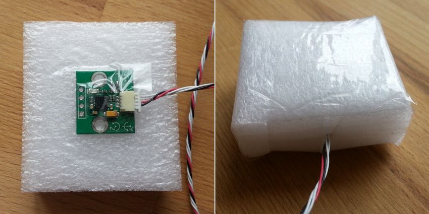
Second IMU sensor
There is an option to install the second IMU sensor on the gimbal's frame. The
advantage is more precise stabilization (you may use lower PID's to get the same
quality) and knowing frame tilting greatly helps 3-axis systems to extend the
range of working angles.
The second IMU should be connected to the same I2C bus as main (in parallel).
Sensors should have different I2C-address (Main IMU – 0x68, Frame IMU – 0x69).
On the original Basecam IMU sensor, address 0x69 may be set by cutting the ADDR bridge, located on the
back side of the sensor.
CAN_IMU can be used as 2nd IMU as well – it has soldered jumper to choose "Frame" or "Main" role.
Mounting the Frame IMU
There are two options where to place the second IMU: below YAW motor and above it. In case of 2-axis
stabilization, there is only one option – above ROLL motor.
© Basecamelectronics® 2013-2018 214. Hardware settings
Frame IMU:
above YAW
YAW
MOTOR
below YAW
(above ROLL)
ROLL PITCH
MOTOR MOTOR
Camera IMU
If the sensor is placed above YAW motor, it helps to stabilize ROLL, PITCH and YAW motors. But the system
becomes less stable during long work (because the frame heading, estimated from the second IMU, may
drift with time and auto-correction may not work in all cases).
If the sensor is placed below YAW motor, it does not help YAW axis stabilization, but its operation is more
reliable. There is a particular option you can choose for this position from: "Below YAW + PID source". It
means that if Frame IMU is mounted below YAW motor it can be used as a data source for the PID
controller. In some cases this can give better result than the main IMU, because mechanical system's “IMU-
Motor” becomes more stiff when its length is shorter and its closed-loop operation becomes more stable.
Like the main (camera) IMU, the frame IMU may be mounted in any orientation, keeping its axis parallel
with the motor's axis.
Configuring the frame IMU
To configure the frame IMU, first of all set its mounting position in the “Hardware” tab, “Frame IMU sensor”
group. Write settings to the board and go to the “Monitoring” tab. Press the button “Frame IMU”:
If the second IMU is connected properly, this button becomes active. After pressing on it, all IMU-related
realtime data corresponds to the frame IMU. You may notice the right panels with arrows are displaying
now angles not for the main, but rather for the frame IMU.
© Basecamelectronics® 2013-2018 224. Hardware settings
Change sensor orientation (axis TOP, RIGHT) and write setting to the board if necessary (board will be
restarted). After restart, calibrate the accelerometer and gyroscope like you did for the main IMU. For the
accelerometer you can do simple calibration or extended 6-point calibration. But for the second IMU,
precise calibration is not so crucial, as for the main IMU.
Precision of angle measurement
A MEMS gyroscope-based IMU gives very good precision, especially compared to single accelerometer. But
it still can be affected by environment, that can reduce the precision and give negative effects like lost
horizon, slowly drifting angles, cross-axis interference (rotation by one axis lead to declination by other
axis). Below are the most common reasons and our recommendations how to solve them:
• Vibrations: try to isolate gimbal from vibrating platform by dampeners.
• Lateral or centrifugal accelerations (fast accelerated slides or movement by a curved trajectory):
consider “Gyro trust” setting.
• Wrong calibration of accelerometer or gyroscope: carefully follow our instructions and check the
validity of calibration from time-to-time.
• Misalignment of sensor's axes and gimalbal motor's axes: pay attention to sensor orientation when
mounting sensor on the gimbal, or apply a correction by "Misalignment correction" parameters later.
• Changes in temperature than affect calibrations: do the temperature calibration
• Drift of heading angle without good reference: install and configure a magnetometer sensor.
• Over-saturation of gyro sensor: prevent rotations faster than 2000 degree/second.
The problem of mutual azimuth drifts of two IMU sensors
Gradual drift of angles taken from Gyro is a normal situation, and you need to take into account it in any
AHRS (attitude and heading reference systems). Additional sensors can be used to correct gyro drift: an
accelerometer and magnetometer.
An accelerometer corrects 2 axes of a gyro by gravitation vector.
A magnetometer corrects 3rd axis by Earth's magnetic field vector.
Complete IMU generally includes 3 sensors (called 9-axis system). Using a magnetometer in gimbals is not
very common since the precision of a magnetometer highly depends on the environment and it is difficult
to calibrate it properly. Fortunately, in the most cases of gimbals usage, the absolute precision of the
azimuth detection is not required. But using two IMUs (first installed on the camera tray, and second
installed on the frame of a gimbal), the azimuth of one sensor has to match the azimuth of another sensor.
In the SimpleBGC32 controller, special algorithms are used to correct mutual azimuth drift. It allows the
system to work stably in almost any conditions.
The following are methods which are automatically applied by the controller to correct absolute drift and
mutual azimuth drift of both sensors:
• The limits caused by a gimbal’s design. For example, if the second sensor is installed below YAW, its
azimuth in normal position always match the azimuth of the first sensor. But when the frame
inclined forward at 90 degrees, this condition is wrong and other methods should be used.
• Detecting rotation of motors by the electric field. If the second sensor is installed above YAW, its
azimuth may not match the azimuth of the first sensor. But if the rotation angle of YAW motor is
known, it is possible to match their azimuths. In the different orders of hardware axes, for example,
Cam-YAW-ROLL-PITCH, this situation appears in any position of the second sensor. Note that this
correction works if motors are switched on, and system was started in “normal position” when
azimuths of both sensors were matched (though additional algorithms are used to synchronize
azimuths, it's better to always take care about proper start position).
© Basecamelectronics® 2013-2018 234. Hardware settings
• Detecting rotation of motors by encoders. Using encoders (at least one installed on YAW axis)
significantly improves the precision of correction.
• Using magnetometer. If a magnetometer is connected to the IMU sensor (frame or camera) then its
azimuth will match True North. The second sensor will be automatically corrected by the
magnetometer by one of the above methods.
• Using precise orientation data from an external AHRS system. Using Serial API, you can provide the
precise orientation of the camera tray or a frame measured by an external system with high-grade
IMU using command "CMD_AHRS_HELPER". In this case, an appropriate sensor will be corrected
using this data, and the second sensor will be corrected by one of the above methods.
• Using AHRS data from flight controller - you can connect UAV autopilot (for example, Ardupilot or
Naza) to the SimpleBGC32 controller by MavLink protocol, to synchronize their attitudes.
There are also a number of methods to manually correct gyro drift:
• Providing the heading angle from an external source. Via adjustable variable
"FRAME_HEADING_ANGLE" you can provide the heading angle to the controller. It will be translated
to the main IMU, if possible, and used as heading reference. The possible case where it may be
used: gimbal is mount statically, so the frame angle does not change. Or, gimbal is mounted on a
crane, and its azimuth is known from it's controller.
* This method is similar to CMD_AHRS_HELPER, but the reference vector is computed automatically from
single variable taking into account frame's attitude.
• Correcting gyro offset manually. If operator can observe a picture from a camera, it can detect a
gyro drift direction and apply correction by adjusting a knob on a remote controller. It can be
linked to the "GYRO_HEADING_CORRECTION" adjustable variable.
Temperature Sensor Calibration
If the gimbal will be used in a wide temperature range, it is necessary to perform what is called a
temperature calibration of the accelerometer and gyroscope. We suggest you do this procedure once
properly for at least the temperature range you will be using the gimbal at. This will eliminate the need to
repeat calibration due to each change of ambient temperature and results in increased stabilization
accuracy for operation within the calibrated temperature range.
Temperature calibration is done through a computer connection with the use of the calibration assistant or
offline by setting the corresponding commands for the board's menu button.
Calibration with the use of GUI is described below. Offline calibration is carried out similarly.
© Basecamelectronics® 2013-2018 24You can also read