GANN HYDROMETTE UNI 1 + UNI 2 - Operating instructions
←
→
Page content transcription
If your browser does not render page correctly, please read the page content below
GANN HYDROMETTE UNI 1 + UNI 2

Operating instructions
1
All copyrights reserved

Reproduction of this manual, also in part, by print, copying or any other procedure
is not permitted unless approved in writing by GANN Mess- u. Regeltechnik GmbH.
This manual has been most carefully composed. The manufacturer and/or supplier
assumes no liability, however, for possible misprints or errors.

Copyright by GANN Mess- u. Regeltechnik GmbH.
Stuttgart, Federal Republic of Germany

                                                  2
3
Technical Specifications - Hydromette UNI 1

(1) MS Connection Socket       for connection of temperature probes PT 100,
                               all active electrodes and infrared sensor IR 40
(2) LCD Readout                for all measurements
(3) Selector Switch            »position M«
                               for measurements using the following active electrodes:
                               MH 34 for moisture measurements on coniferous
                               wood in the range between 40 and 200 % m.c.
                               MB 35 for non-destructive moisture measurements of
                               concrete surfaces
                               B 50 for non-destructive moisture measurements of set
                               inorganic construction materials (concrete, cement floor-
                               ing, etc.)
                               RF-T 28 for air humidity measurements,
                               RF-T 31 for air humidity measurements,
                               RF-T 32 for air humidity measurements,
                               IR 40 for surface temperature measurements with infrared
                               sensor,
                               »position 200°«
                               for temperature measurements up to 200 °C with elec -
                               trodes RF-T 28, RF-T 31, RF-T 32 and temperature pro-
                               bes PT 100,

                                        4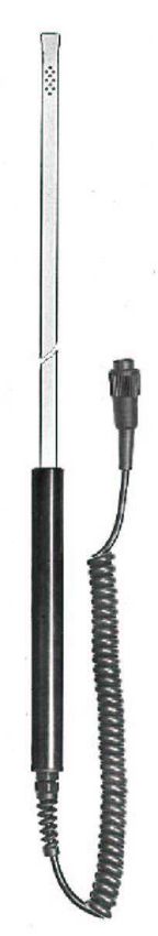
»position 600°«
                                          for temperature measurements up to 600 °C using
                                          temperature probes PT 100,
                                          »position Batt«
                                          for battery check.
(4) Measuring Key                         ON/OFF

Battery Check
Set selector switch (3) to position »Batt« and press measuring key (4). The reading displayed
should be higher than 7.5 digits. If it is 7.5 digits or lower, the battery is exhausted and should be
replaced or recharged if a rechargeable battery is being used. The cover of the battery
compartment can be lifted by means of a coin inserted into the slot. It is recommendable to replace
or recharge the battery once the reading of the battery check is below 8 digits.

Power Source
The meter is fitted, as standard, with a 9 V dry battery IEC 6 F 22 or IEC 6 LF 22.
It is recommended to use alkali-mangan batteries.
A rechargeable nickel-cadmium battery can be fitted (optional accessory). It can be recharged from
any A.C. lighting supply socket by means of the charging unit supplied with this special battery.

Calibration
The meter is fitted with an electronic setting device, making manual calibration or adjustment
unnecessary.

                                                    5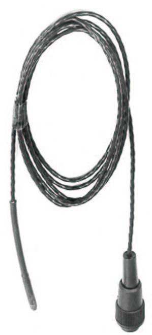
Measuring ranges

Wood Moisture, position »M«:                40 - 200 % m.c.      on coniferous wood using active
                                                                 electrode MH 34
Structural Moisture, position »M«:            0 - 199 digits     non-destructive measurement
                                                                 with active electrode B 50/B60
                                              0,3 - 8,5 %        of dry weight with active electrode
                                                                 B 50 and conversion table
                                              1-8%               of dry weight with active electrode
                                                                 MB 35 on non-destructive surface
                                                                 measurement of concrete
Air Humidity, position »M«:                   7 - 98 % R.H.      with live electrodes RF-T 28,
                                                                 RF-T 31, RF-T 32 and RF-T 36
Temperature 1, position »200°«:      -200 - +200 °C with temperature probes PT 100
Temperature 2, position »600°«:      -200 - +600 °C with temperature probes PT 100
Temperature 3, position »M«:         -20,0 - +200 °Cwith infrared sensor IR 40.

If the measured value exceeds the measuring capacity, the figure »1« appears on the left side of
the display screen (2).

Dimensions

Plastic casing: Length 140 mm x Width 90 mm x Height 42/50 mm.
Weight: about 220 g without accessory.

                                                  6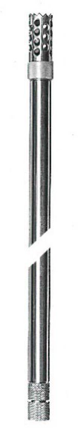
7
Technical Specifications - Hydromette UNI 2

(1) BNC Connection Socket      for connection of electrodes designed for testing set build-
                               ing materials according to the resistance method
(2) MS Connection Socket       for connection of temperature probes PT 100, all active
                               electrodes and infrared sensor IR 40
(3) LCD Readout                for all measurements
(4) Selector Switch            »position B«
                               for measurement of set building materials according to the
                               resistance measuring method
                               »position M«
                               for measurements using the following active electrodes:
                               MH 34 for moisture measurements on coniferous wood in
                               the range between 40 and 200 % m.c.
                               MB 35 for non-destructive moisture measurements of
                               concrete surfaces
                               B 50/B 60 for non-destructive moisture measurements of
                               set inorganic construction materials (concrete, cement
                               flooring, etc.)
                               »position M«
                               RF-T 28 for air humidity measurements,
                               RF-T 31 for air humidity measurements,

                                        8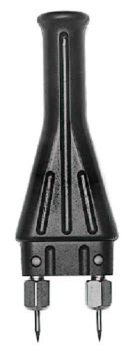
»position M«
                                           RF-T 32 for air humidity measurements,
                                           RF-T 36 for air humidity measurements,
                                           IR 40 for surface temperature measurements with infrared
                                           sensor,
                                           »position 200°«
                                           for temperature measurements up to 200 °C with elec -
                                           trodes RF-T 28, RF-T 31, RF-T 32, RF-T 36 and
                                           temperature probes PT 100,
                                           »position 600°«
                                           for temperature measurements up to 600 °C using pro bes
                                           PT 100,
                                           »position Batt«
                                           for battery check.
(5) Measuring Key                          ON/OFF

Battery Check

Set selector switch (4) to position »Batt« and press measuring key (5). The reading displayed
should be higher than 7.5 digits. If it is 7.5 digits or lower, the battery is exhausted and should be
replaced or recharged if a rechargeable battery is being used. The cover of the battery
compartment can be lifted by means of a coin inserted into the slot.
It is recommendable to replace or recharge the battery once the reading of the battery check is
below 8 digits.

                                                     9
Power Source
The meter is fitted, as standard, with a 9 V dry battery IEC 6 F 22 or IEC 6 LF 22. It is
recommended to use alkali-mangan batteries. A rechargeable nickel-cadmium battery can be fitted
(optional accessory). It can be recharged from any A.C. lighting supply socket by means of the
charging unit supplied with this special battery.
Calibration
The meter is fitted with an electronic setting device, making manual calibration or adjustment
unnecessary.
Measuring ranges
Structural Moisture, position »B«: 0 - 80 digits with graphs for converting read
ings into percent of moisture for
various building materials
Structural Moisture, position »M«: 0 - 199 digits non-destructive measurement
with active electrode B 50/B60
0,3 - 8,5 % of dry weight with live electrode
B 50 and conversion table
1-8% of dry weight with live electrode
MB 35 on non-destructive surface
measurement of concrete
Wood Moisture, position »M«: 40 - 200 % for measurement on coniferous
wood using the active electrode
MH 34
Air Humidity, position »M«: 7 - 98 % R.H. with active electrodes RF-T 28,
RF-T 31, RF-T 32 and RF-T 36
10Temperature 1, position »200°«: -200 - +200 °C with temperature probes PT 100
Temperature 2, position »600°«: -200 - +600 °C with temperature probes PT 100
Temperature 3, position »M«: -20,0 - +200 °Cwith infrared sensor IR 40.
If the measured value exceeds the measuring capacity, the figure »1« appears on the left side of
the display screen (3).
Dimensions
Plastic casing: Length 140 mm x Width 90 mm x Height 42/50 mm.
Weight: about 220 g without accessory.
General instructions for UNI 1 and UNI 2
Admissible ambient temperatures
Storage: 5 to 40 °C; temporarily -10 to 60 °C
Operation: 0 to 50 °C, short term -10 to 60 °C not c ondensing
The meter including accessory must not be stored or used in aggressive air or air contaminated by
solvents.
General Remark
The instructions for use of the meter and of the electrodes should be carefully observed to avoid
measuring errors which may occur when trying to simplify the measuring procedure.
Warning
Make sure in any case prior to drilling holes for measuring probes or before driving electrode pins
into walls, ceilings or floors that this happens away from power lines, water pipings or other supply
pipes.
11Measuring Electrodes and Other Accessory
Active electrode MH 34 (Ref.No. 3350)
with integrated measuring circuit, for measurement of high moisture
contents in coniferous wood, specially in case of water-borne storage
and pre-sorting of freshly cut timber for kiln drying.
Measuring range: 40 to 200 % m.c.
12Active electrode B 50 (Ref. No. 3750)
with integrated measuring circuit, designed for non-destructive
location of moisture concentration in construction materials and
moisture distribution in walls, ceilings and floors.
It works according to a patented measuring procedure and generates a
concentrated high frequency field with substantial penetration depth.
Measuring range: 0 to 199 digits, classification by table,
0.3 to 8.5 % of dry weight, conversion into % of
moisture by table.
0.3 to 6.5 % CM, conversion by table according
to material tested.
13Active electrode B 60 (Ref. No. 3760)
with integrated measuring circuit, designed for non-destructive
location of moisture concentration in construction materials and
moisture distribution in walls, ceilings and floors.
It works according to a patented measuring procedure and
generates a concentrated high frequency field with substantial
penetration depth.
With built-in limit value selector and acoustic signal generator.
Setting range: 20 to 140 digits.
Measuring ranges: 0 to 199 digits by table.
0.3 to 8.5 % of dry weight conversion by
table according to material tested.
0.3 to 6.5 % CM, conversion by table
according to material tested.
14Active electrode MB 35 (Ref. No. 3770)
with integrated measuring circuit, designed for surface measure-
ment of concrete, in particular prior to coating or gluing.
Measuring range: 1 to 8 % m.c. of dry weight according to oven
test, direct display, no conversion table required.
Test Standard (Ref. No. 6073)
for checking the active electrode MB 35.
15Special electrode RF-T 28 (Ref.No. 3155)
with integrated measuring circuit, for measurement of air humidity
and air temperature, complete with connection cable.
Measuring range: 7 to 98 % R.H. and -10 to +80 °C
Response time: about 20 seconds for 90 % of the humidity
difference at an ambient temperature of 20 °C,
or about 120 seconds for 90 % of temperature
variation.
Filter Cap (Ref. No. 3156)
of sintered bronze for use with electrode RF-T 28 in dust laden
air or at high air speed.
16Special electrode RF-T 31
for measurement of atmospheric moisture, water activity value or
equilibrium moisture in bulk materials and solid substances, e.g.
brickwork and other building materials.
Measuring range: 7 to 98 % R.H.
-10 to +80 °C.
Sensor tube: dia. 10 mm
Sintered filter tip 32 mm long.
Insertion length 250 mm (Ref. No. 3131)
Insertion length 500 mm (Ref. No. 3132)
Bore hole adapter
with closing plug, for use with plug-in sensor RF-T 31 for equilibrium
moisture measurement in brick-work or building materials.
For bore holes up to 150 mm in depth (Ref. No. 5615)
For bore holes up to 250 mm in depth (Ref. No. 5625)
For bore holes up to 500 mm in depth (Ref. No. 5650)
17Blade Sensor RF-T 32
for measurement of atmospheric humidity, water activity value and
equilibrium moisture in paper, leather, textile and tobacco stores, etc.
Measuring range: 7 to 98 % R.H.
-10 to +80 °C.
Flat elliptical probe abt. 10 x 4 mm.
Insertion length 250 mm (Ref. No. 3133)
Insertion length 500 mm (Ref. No. 3134)
Sensor Check
Test and calibrating box for
Probe RF-T 28 (Ref. No. 5728)
Probe RF-T 31 (Ref. No. 5731)
Probe RF-T 32 (Ref. No. 5732)
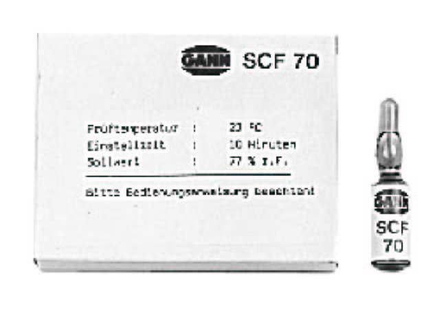
Test and Calibrating Fluid
for checking and recalibrating all electrodes type RF-T.
Package of 5 ampoules of test fluid for sensor check, including
absorbing fleece, sufficient for 5 tests or recalibrations.
SCF 30 for the range of 10 to 50 % R.H. (Ref. No. 5753)
SCF 70 for the range of 50 to 90 % R.H. (Ref. No. 5757)
SCF 90 for the range of 80 to 98 % R.H. (Ref. No. 5759)
18Special electrode RF-T 36 (Ref. No. 3136)
for measurement of air humidity and air temperature, water activity
value or equilibrium moisture in rooms, warehouses or solid
substances (e.g. concrete, subflooring, masonry, etc.)
Measuring Range: 5 to 98 % R.H.
-5 to +60 °C
Dimensions: 82 x 80 x 55 mm
Sensor tube: length 55 mm, dia. 12 mm
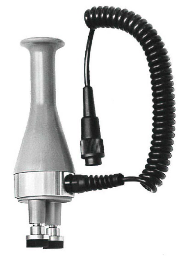
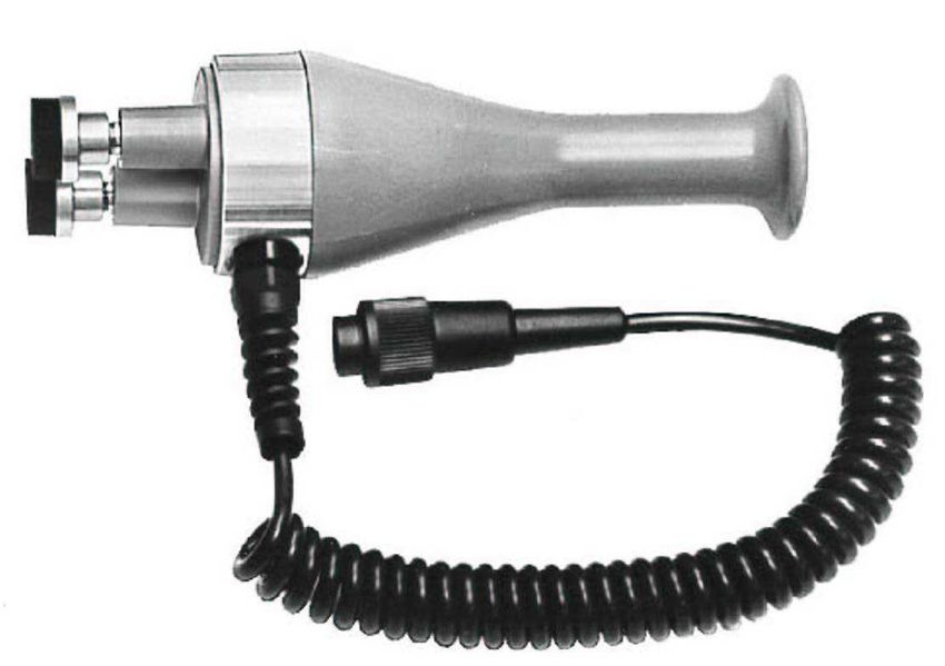
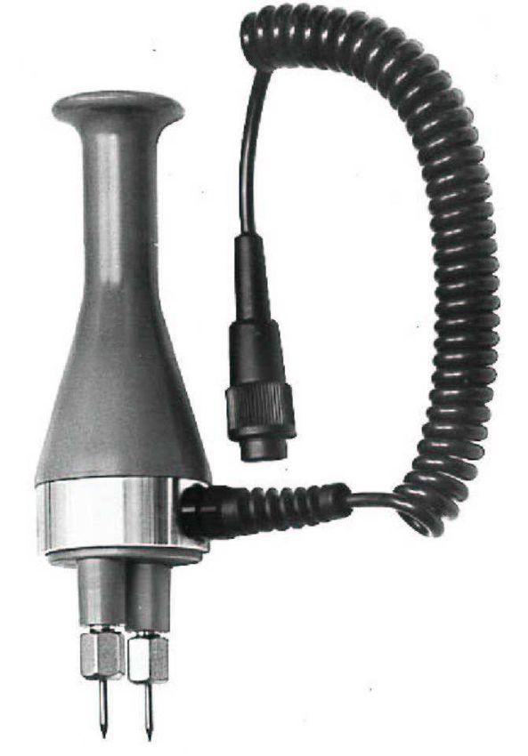
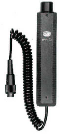
19Infrared Surface Temperature Sensor IR 40
(Ref. No. 3150)
Contactless temperature measurement from -20 to +199.9 °C,
resolution 0.1 °C, emissivity permanently set at 9 5 %, ratio of
measured area to distance 2.5:1 (Ø 45 mm at a distance of
100 mm), sensor length 185 mm x 36 x 33 mm, coiled cable
320/1200 mm.
An ideal sensor for detection of heat bridges, determination of
the dew point temperature, measurement of live, moving or vi-
brating components as well as measurement of components
with low heat capacity, e.g. wood, glass, insulating materials,
for location of the position of the heating tubes of a floor heat-
ing, etc.
Matt-black stickers IR 30/E 95 (Ref. No. 5833)
Measurement spot 30 mm Ø, emissivity 95 %, e.g. for meas-
urement of metallic surfaces.
20Pt 100 Temperature Probes
Temperature Probe ET 10 (Ref. No. 3165)
Robust stick-in temperature probe for solid and bulk materials
and liquids, measuring range -50 to +250 °C .
Temperature Probe TT 40 (Ref. No. 3180).
Robust immersion and combustion gas temperature probe with
long sensor tube, measuring range -50 to +350 °C
Temperature Probe LT 20 (Ref. No. 3190)
Quick responding air/gas temperature probe with long sensor
tube, measuring range -20 to +200 °C.
Temperature Probe TT 30 (Ref. No. 3185)
Robust immersion and combustion gas temperature probe with
short sensor tube, measuring range -50 to +350 °C.
Temperature Probe ET 50 (Ref. No. 3160)
Quick responding air/gas temperature probe for soft solid sub-
stances, bulk materials and fluids, measuring range -50 to 250 °C.
Temperature Probe OTW 90 (Ref. No. 3175)
Angled special surface temperature probe, e.g. for veneer
presses, etc., measuring range -50 to +250 °C.
Temperature Probe OT 100 (Ref. No. 3170)
Spring loaded, low mass surface temperature probe, e.g. for
wall surfaces, etc., measuring range -50 to +250 °C.
21Silicone Heat Conducting Paste (Ref. No. 5500)
To improve heat transmission on rough surfaces or where there
are contact problems. Unconditionally recommended with OT 100.
Flexible Temperature Probes with Teflon insulated connection
cable, for solid and bulk materials as well as liquids up to 120 °C.
FT 2 with Teflon cable 2 m long
(Ref. No. 3195)
FT 5 with Teflon cable 5 m long
(Ref. No. 3196)
FT 10 with Teflon cable 10 m long
(Ref. No. 3197)
FT 20 with Teflon cable 20 m long
(Ref. No. 3198)
22Use of Active Electrode MH 34
for measurement of high moisture contents (above 40 % m.c.) in coniferous wood
The active electrode MH 34 has been developed specially for measurement of very high moisture
contents in coniferous wood (pine, fir, spruce). It is suitable particularly for pre-sorting freshly cut
timber for kiln drying and for monitoring water-borne borne storage.
The measuring range extends from 40 to 199 % m.c. and the reading is displayed direct in per
cents of moisture. Moisture values below 40 % m.c. are beyond the measuring capacity of this
special electrode and readings below 40 % m.c. should, therefore, be disregarded. For
measurements in the range below 40 % m.c. the electrodes M 18 and M 20 should be used.
The active electrode MH 34 is equipped and also adjusted to pins 23 mm in length, and the
readings obtained represent the average moisture content of those section of the board or piece of
wood penetrated by the pins. We do not recommend using longer or shorter pins as this will affect
the accuracy of reading.
Press, or drive cautiously, both pins into the wood to be measured until both cap nuts touch it.
Connect electrode to the meter socket (1) (UNI 1) or (2) (UNI 2) and set selector switch (3) (UNI 1)
or (4) (UNI 2) to position »M«. Then press measuring key (4) (UNI 1) or (5) (UNI 2) and read result
in per cent of moisture.
When withdrawing the electrode, the pins can be loosened by slight sideways rocking movements
across the grain. The cap nuts should be tightened by means of a spanner prior to a series of
measurements.
23Instructions For Non-Destructive Measurement of the Moisture Con-
tent of Building Materials Using the Electrodes MB 35 and B 50/B 60
Set selector switch (3) (UNI 1) or (4) (UNI 2) to position »M«.
Connect electrode to meter socket (1) (UNI 1) or (2) (UNI 2) and apply it as described hereinafter.
Press measuring key (4) (UNI 1) or (5) (UNI 2) and read result displayed by LCD readout (2)
(UNI 1) or (3) (UNI 2).
Active Electrode MB 35
The active electrode MB 35 has specially been developed for surface moisture measurement on
concrete and sub-floorings and are suitable particularly for moisture checks prior to coating or
gluing. The measuring range extends from 1.0 to 8.0 % of dry weight (according to oven test). The
reading is displayed direct in per cent of moisture.
The electrode is fitted, as standard equipment, with the surface measuring caps M 20-OF 15 with
elastic contact pads of conductive plastic material. The pads are glued on their support which in
turn are screwed on the electrode handle. Make sure that the measuring caps are properly
screwed down. Exchange the elastic measuring pads in case of wear or damage. Fix the new pads
on the support plate by means of a commercially available instant adhesive on cyanate basis.
Use of active electrode MB 35
Connect electrode to the meter and press the measuring pads firmly on the concrete. Press
measuring key and read off result in per cent of dry weight. The surface of the concrete should be
cleaned from dust and separating agents or other contaminations to ensure correct measuring
results.
24Active Electrode B 50 und B 60
The active electrodes B 50 and B 60 are dielectric moisture sensor with integrated circuitry. It is
intended specifically for determining moisture absorption and moisture distribution in building
materials such as for example brickwork, concrete, screed, wood, insulating materials, etc.
The basis of measurement is the dielectric constant measurement method. Between the ball
electrode and the material to be measured with which it comes into contact, a measurement field is
set up, which is affected by the density of the building material to be measured and its moisture
content. If the density of the material is constant, changes in the capacity field can be matched to a
change in the moisture content of the material being measured.
The measuring range extends from 0 to 199 digits, i.e. the displayed values are relative values.
They indicate the distinction between dry and moist building material. The higher the measured
value, the higher the moisture content of the material being measured. Drawing conclusions about
the actual moisture content in per cent from the relative measured is only permissible in the case of
a normal drying process.
The bulk density of the building material to be measured is in this case a factor of influence which
has to be taken into account. High bulk densities lead to higher displayed values, independently of
the moisture content.
Use of active electrode B 50 and B 60
In order to avoid influencing of the measurement result by the hand of the operator, the electrode
should only be held by its lower half during checking and measurement. The upper half of the
electrode must remain free.
25Special feature of the active electrode B 60
The active electrode B 60 is equipped with a selector switch to set a limit value.
It allows in conjunction with the also incorporated acoustic signal generator judgement of the tested
building material without direct sight on the LCD readout.
Whenever the readings exceed the preset limit value, a whistle signal sounds.
In the range between 30 and 70 digits, the signal tolerance is ± 2 digits, and in the range between
80 and 140 digits ± 3 digits.
26Checking
Unless it is permanently fixed, push the ball rod into the socket on the top of the electrode and
connect the cable to the measuring instrument. Hold the electrode in the air and press the
measuring key of the measuring instrument. It must display a value between -5.0 and 5.0 digits. If it
fails to display an admissible value, increase or, as the case may be, reduce the reading by slightly
turning the potentiometer located behind an opening in the upper half of the grey plastic handle of
the active electrode by means of a small screwdriver.
Measurement
Press the measuring key of the moisture meter and bring the electrode ball into contact with the
surface to be tested. The electrode ball must be in firm contact with the material. As far as possible
the electrode should be held perpendicularly to the surface being measured. In corners
measurement is only possible up to a distance of approx. 4 - 5 cm from the edge. The list below is
intended to serve as a guide to the displayed values to be expected in practice and their
classification:
Wood dry 25 - 40 digits
moist 80 - 140 digits
Living area dry 25 - 40 digits
brickwork moist 100 - 150 digits
Basement brickwork dry 60 - 80 digits
moist 100 - 150 digits
Depending on the bulk density, displays of more than 130 digits would indicate the presence of free
water. In the case of covered metal parts (reinforcing steel, pipes, ducting, plaster supporting strips,
etc.) even if the environment is otherwise dry the display jumps to approximately 80 digits (if the
27covering is very thin, even higher). This should be taken into account when assessing the
displayed values.
Display Values (Digits) in Relation to the Material Bulk Density
Density
Corresponding Relative Air Humidity
(specific wt.)
of the
30 -
50 70 80 90 95 100
building
material Display in Digits
kg/m³
very normal semi very
dry dry dry moist moist wet
up to 600 10 - 20 20 - 40 40 - 60 60 - 90 90 - 110 more than
100
600 -1200 20 - 30 30 - 50 50 - 70 70 - 100 100 - 120 more than
120
1200 -1800 20 - 40 40 - 60 60 - 80 80 - 100 110 -130 more than
130
above 1800 30 - 50 50 - 70 70 - 90 90 - 120 120 - 140 more than
140
28Display Values (Digits) in Percents of Weight
Display (Digits) 40 50 60 70 80 90 100 110 120 130
Cement
weight
mortar 1.8 2.2 2.7 3.2 3.6 4.1 4.5 5.0 5.5 5.9
%
Anhydrite
weight
screed 0.1 0.3 0.6 1.0 1.4 1.8 2.2 2.5 2.9 3.3
%
Concrete
weight
B 15, B 25, 1.3 1.9 2.5 3.2 3.8 4.4 5.0 5.6 6.2
%
B 35
Cement
weight
mortar 1.8 2.7 3.5 4.6 6.0 7.0 7.8
%
Lime
weight
mortar 0.6 2.0 3.3 4.5
%
Lime-cement
weight
plaster 2.2 3.6 5.0 6.4 7.8 9.2 10.6 11.0
%
mixture
Gypsum
weight
plaster 0.3 0.5 1.0 2.0 3.5 6.5 10.0
%
29Readings in digits depending on the moisture in weight per cent. The displayed values are guide
values. They refer to a depth of 1.5 to 3 cm in the case of a measurement on the surface and a
normal drying process. Weight percentages are according to an oven test at 105 °C, for gypsum
and anhydrite binders at 40 °C.
Note
The references and tables concerning permissible or customary moisture proportions in practice
contained in the Operating Instructions and the general definitions have been taken from the
specialist literature. No guarantee of correctness can therefore be given. The conclusions each
user may draw for his own purposes from the measurement results are based on the individual
circumstances and the knowledge he has gained from his professional activities.
30Instructions for Moisture Measurement in Building Materials on the Basis of
the Measurement of the Relative Air Humidity
using the active electrodes RF-T 31 and RF-T 36
Set selector switch (3) (UNI 1) or (4) (UNI 2) to position »M«.
Connect selected active electrode to the meter socket (1) (UNI 1) or (2) (UNI 2).
Press measuring key (4) (UNI 1) or (5) (UNI 2) and read off result displayed (in % R.H.) by the LCD
readout (2) (UNI 1) or (3) (UNI 2).
Technical specifications
Measuring range: 5 to 98 % R.H. for short periods.
For continuous or long period measurements in
the range above 80 % R.H., a special calibra-
tion is required for the measuring sensors.
Admissible operating temperature -10 °C to +60 °C f or short periods,
for the meter and the electrodes: 0 °C to +50 °C for long periods.
Admissible ambient conditions
for the storage of the meter -10 °C to +60 °C for short periods
and the electrodes: 5 °C to +40 °C for long per iods.
5 % to 98 % R.H. for short periods *)
35 % to 70 % R.H. for long periods *)
*) not condensing
31Measurement of the Relative Air Humidity /
Water Activity in Building Materials
This method is usually used for depth measurements in old buildings (sandstone, rough stone, wet
walls with efflorescence, etc.) where measurements based on the resistance measurement method
give no reproducible results. For this purpose the active electrode RF-T 31 with special tube
lengths of 250 and 500 mm is used. In the case of measurements over a longer period at several
points or at various depths, the drilled holes should be secured and closed by means of a masonry
sleeve / bore hole adapter.
The method of measuring the relative air humidity / equilibration moisture in screeds is chiefly used
in Great Britain and the Scandinavian countries. The active electrode RF-T 36 has been specially
developed for this. Compared with non-destructive measurement or resistance measurement it is
however very time-consuming and required relatively large holes. Reliability for the floor layer/
finisher is but on the other hand very good, if it is possible to wait for moisture balance (relative air
humidity of the surroundings equal to that of the hole). This method also increases reliability in
cases where there is not adequate information concerning the composition of the screed.
Use of the active electrode RF-T 31
For deep measurements in building materials by means of the relative air humidity, in addition to
the probe with a sensing tube length of 250 or 500 mm a bore hole adapter consisting of a masonry
sleeve of 150, 250 or 500 mm length should be used.
32For the measurement a blind hole of 16 mm diameter should be drilled down to the required
measuring depth. It is important to use a sharp drill, with a high number of impacts and low speed.
If the hole should heat up strongly it is necessary to wait for temperature equalization (30 - 60
minutes) before taking the measurement. The hole should be cleared of dust (by blowing). Then
the hole adapter should be introduced as far as the end of the hole, pressed in and at the same
time turned to the right. The adapter should be tightened to such an extent that the entire screw
thread sits firmly in the brickwork, concrete, etc. Then the closure rod for sealing or the electrode
RF-T 31 should be inserted.
The moisture balance in the hole is achieved when temperature equalization exists (the same
temperature in the hole, adapter and sensor tube) after approximately 30 minutes. Then the
measurement value can be read off and assessed by means of the following graph.
Use of the active electrode RF-T 36
For the measurement a blind hole of 12 - 14 mm diameter and minimum 25 mm and maximum 50
mm deep must be drilled. The depth of drilling depends on the required measurement depth or
thickness of the screed. Blow the hole clear of dust and wait for temperature equalization. Push the
piece of foam enclosed on to the electrode tube of the probe and adjust the distance and to seal it,
then introduce it into the hole.
The moisture balance in the hole is achieved when temperature equalization exists (the same
temperature in the hole, adapter and sensor tube) after approximately 30 minutes. Then the
measurement value can be read off and assessed by means of the following graph.
3334
Damage to the Sensor

The sensor can be rendered irreparable as a result of various mechanical or environmental
influences. These include in particular:

- direct contact between the sensor and the fingers,
- direct contact with solid or adhesive materials or objects,
- measurement in atmospheres containing solvents, oil vapours and other high proportions of
  armful substances.

Measuring Errors

Measurements below 20 % relative humidity and above 80 % relative humidity should be avoided
over a long period as far as possible. In order to make exceeding the measuring range particularly
easy to recognize, above 98 % relative humidity a »1« appears on the left hand side of the display
instead of the measured value. Other measured value distortions can occur as a result of screening
with parts of the body (e.g. the hand) or blowing or speaking/breathing in the direction of the
sensor.

Note

The sensor is not designed for continuous measurements above 80 % relative humidity. If
continuous measurements have to be made in extreme regions special adjustments should be
made by means of sensorcheck and a calibration liquid.

                                                    35
Instructions for Air Humidity Measurement
using the active electrodes RF-T 28, RF-T 31, RF-T 32 and RF-T 36
Set selector switch (3) (UNI 1) or (4) (UNI 2) to position »M«.
Connect electrode to the meter socket (1) (UNI 1) or (2) (UNI 2).
Press measuring key (4) (UNI 1) or (5) (UNI 2) and read off result displayed (in % R.H.)
by the LCD readout (2) (UNI 1) or (3) (UNI 2).
Technical Specifications
Measuring range: 5 to 98 % R.H. for short periods.
For continuous or long period measurements in
the range above 80 % R.H., a special calibra-
tion is required for the measuring sensors.
Admissible operating temperature -10 °C to +60 °C f or short periods,
for the meter and the electrodes: 0 °C to +50 °C for long periods.
Admissible ambient conditions
for the storage of the meter -10 °C to +60 °C for short periods
and the electrodes: 5 °C to +40 °C for long per iods.
5 % to 98 % R.H. for short periods *)
35 % to 70 % R.H. for long periods *)
*) not condensing
36Use of the active electrode RF-T 28
Hold the electrode in the air or fasten it at the desired measurement site and start the measuring
process. For particularly precise measurements, especially below the usual room temperature (abt.
20 °C) or if there are substantial temperature diff erences between the electrode or meter and their
surroundings, they should be exposed to the ambient atmosphere for approx. 10 - 15 minutes until
temperature equalization. The sensor adapts itself to the surrounding atmosphere even in the
switched-off condition.
Response time of the air humidity sensor
The response time of the sensor is very short so even gently moving air (generated by a slightly
opened door or a window being not tight) may affect the reading. This is why no absolute standstill
of the value displayed can be achieved unless the sensor is installed in an airtight box.
The response time of the sensor in gently moving air is as follows for ambient temperatures from
20 °C to 25 °C
for 90 % of the humidity difference, approx. 20 seconds,
for 95 % of the humidity difference, approx. 30 seconds.
The adjustment time in still air or at very low air movement can be reduced by moving or turning
the electrode (ventilating the sensor).
Filter cap for electrode RF-T 28
For measurements in dust laden air, at emission of harmful substances or at high air speed, a
sintered filter cap can be fitted after removal of the protection cap with venting slots. For protection
of the sintered filter, fix then the plastic cap again.
If the filter becomes dirty it can be washed in residue-free cleaning liquid and/or blown from inside
outwards with compressed air. With the sintered filter inserted, the response time will be
considerably prolonged.
37Use of the active electrode RF-T 31
The sensor RF-T 31 can be supplied with insertion length of 250 or 500 mm and is mainly used for
measuring the relative air humidity or the AW value in places difficult of access, in air ducts, in bulk
materials or, in combination with a special adapter, in solid substances (e.g. brickwork, concrete,
etc.).
Hold the electrode at the point of measurement in the air or insert it or attach it at the required point
with a fixture and start the measurement process. For particularly precise measurements, in
particular at temperatures below usual room temperature (abt. 20 °C) or when there are
considerable temperature differences between the actual temperature of the electrode or of the
measuring instrument and that of the surrounding atmosphere, the instrument with its electrode
should be exposed to the ambient climate for approximately 10 to 15 minutes or until temperature
equalization.
Here too, the sensor adapts itself to the surrounding atmosphere without being switched on. If it
becomes dirty, the sintered filter cap can be washed in residue free cleaning liquid and/or blown
from inside outwards with compressed air.
Response time of the air humidity sensor RF-T 31
The response time is delayed by the sintered filter cap. In exceptional cases it can be unscrewed.
However, if this is done the danger of damage to the sensor is increased considerably. The
response time of the air humidity sensor in moving air, with an ambient temperature of 20 to 25 °C
is
- for 90 % of the moisture difference without filter approx. 20 sec., with filter approx. 5 min., and
- for 95 % of the moisture difference without filter approx. 30 sec., with filter approx. 15 min.
38Use of the active electrode RF-T 32
The sensor RF-T 32 is available with insertion lengths of 250 and 500 mm and is mainly used for
measuring the relative air humidity or the AW value in places difficult of access or in stacks of
paper, leather, textile, tobacco, etc.
Hold the electrode at the point of measurement in the air or place it at the required point and start
the measurement process. For particularly precise measurements, in particular at temperatures
below usual room temperature (abt. 20 °C) or when t here are considerable temperature differences
between the actual temperature of the electrode or of the measuring instrument and that of the
surrounding atmosphere, the instrument with its electrode should be exposed to the surrounding
atmosphere for approximately 10 to 15 minutes or until temperature equalization. The sensor
adapts
itself to the surrounding atmosphere even if it is switched off.
Note
If it becomes dirty, the filter cloth inserted cannot be washed in cleaning liquids and /or blown clear
with compressed air from inside to outside. Therefore its use in dusty media should be avoided.
Cleaning should only be carried out from outside using a soft brush.
Response time of the air humidity sensor RF-T 32
The response time is delayed by the filter cloth and the metal tube. The response time of the air
humidity sensor in moving air, with an ambient temperature of 20 to 25 °C is:
- approx. 3 minutes for 90 % of the humidity difference, and
- approx. 10 minutes for 95 % of the humidity difference.
39Use of the active electrode RF-T 36
The electrode RF-T 36 was developed among other things for semi-stationary (electrode remains
at the measuring point - display unit is mobile when in use) air humidity and air temperature
measurement in interiors, storage bays, etc.
Attach the electrode at the measuring location or at the required point and start the measuring
process. For particularly precise measurements, in particular at temperatures below room
temperature (abt. 20 °C) or if there are significan t temperature differences between the
temperature of the electrode itself and that of the surrounding atmosphere (measurement
immediately after assembly) the electrode should be exposed to the surrounding atmosphere for
approximately 10 to 15 minutes or until temperature equalization. The sensor adapts itself to the
surrounding atmosphere even while being switched-off.
Response time of the air humidity sensor RF-T 36
The response time is delayed by the filter cap. In exceptional cases it can be unscrewed.
However, if this is done the danger of damage to the sensor is increased considerably.
The response time of the air humidity sensor in moving air, with an ambient temperature
of 20 to 25 °C is:
- approx. 20 sec. for 90 % of the humidity difference without filter or
- approx. 3 min. with filter, and
- approx. 30 sec. for 95 % of the humidity difference without filter, or approx. 10 min. with filter.
40Note
If it becomes dirty, the inserted filter cloth can only be washed in distilled water and/or blown clear
with slight excess pressure from inside outwards. Therefore its use in very dusty media should be
avoided. Preferably the cleaning should be carried out from outside using a soft brush.
41Synoptical table of dew point temperatures
as dictated by the air temperature and air relative humidity
Dew point temperature in °C at an air relative humi dity of
Air
temperature
30 % 40 % 50 % 60 % 70 % 80 % 90 % Saturation moisture
°C = quantity of water
°C °C °C °C °C °C °C in g/m³
+30 10,5 14,9 18,5 21,2 24,2 26,4 28,5 30,4
+28 8,7 13,1 16,7 19,5 22,0 24,2 26,2 27,2
+26 7,1 11,3 14,9 17,6 19,8 22,3 24,2 24,4
+24 5,4 9,5 13,0 15,8 18,2 20,3 22,2 21,8
+22 3,6 7,7 11,1 13,9 16,3 18,4 20,3 19,4
+20 1,9 6,0 9,3 12,0 14,3 16,5 18,3 17,3
+18 0,2 4,2 7,4 10,1 12,4 14,5 16,3 15,4
+16 -1,5 2,4 5,6 8,2 10,5 12,5 14,3 13,6
+14 -3,3 -0,6 3,8 6,4 8,6 10,6 12,4 12,1
+12 -5,0 -1,2 1,9 4,3 6,6 8,5 10,3 10,7
+10 -6,7 -2,9 0,1 2,6 4,8 6,7 8,4 9,4
+8 -8,5 -4,8 -1,6 0,7 2,9 4,8 6,4 8,3
+6 -10,3 -6,6 -3,2 -1,0 0,9 2,8 4,4 7,3
+4 -12,0 -8,5 -4,8 -2,7 -0,9 0,8 2,4 6,4
+2 -13,7 -10,2 -6,5 -4,3 -2,5 -0,8 0,6 5,6
0 -15,4 -12,0 -8,1 -5,6 -3,8 -2,3 -0,9 4,8
42Test and Calibrating Instructions for the Relative Humidity Circuitry
of the Electrodes RF-T 28, 31 and 32 Using the Sensorcheck
General Comments
In general one has to differentiate between a test, a possibly necessary re-calibration and a special
calibration for continuous measurement of more than 80 % humidity. Three test and calibrating
liquids are available for the ranges of 10 to 50 %, 50 to 90 % and 80 to 98 %. The latter liquid is
intended for special calibration of the high humidity range and is not to be used for general test or
calibrating purposes. For testing or calibration of the standard moisture range, the liquid SCF 70 is
to be employed.
During testing or calibration, the electrode, the sensorcheck and the liquid must be of the same
temperature. This temperature must be maintained throughout the procedure. Changes of
temperature may be caused by a draft, by breathing or blowing or by holding the electrode tube,
the sensorcheck or the liquid-ampoule in one's hand. Wrapping these components in Styropor or
similar insulating material is recommended.
Please follow the instructions stated on the wrapper of the liquid-ampoule regarding test, calibration
and nominal value data closely.
43Testing
Different sensorcheck top pieces are required for each of the three types of electrodes.
The following test sequence must be observed:
1. Unscrew sensorcheck top from bottom.
2. Electrode RF-T 28: Carefully pull-off the protective cap. If used, remove the dust cap first.
Electrode RF-T 31: Unscrew the sinter filter cap and withdraw it carefully only along the
axis of the tube extension. Tilting the sinter filter may cause damage to
the moisture sensor.
Electrode RF-T 32: This electrode requires no special preparation. Do not dismantle it.
3. Electrode RF-T 28: Plug the top of the sensorcheck to the electrode and push it on lightly
(conical fit).
Electrode RF-T 31: Plug the top of the sensorcheck over the moisture sensor of the elec-
trode and screw to the thread of the electrode tubing. Use no force and
do not tighten it securely.
Electrode RF-T 32: Insert the oval tubing of the electrode, perforated side downward, hori-
zontally into the top part of the sensorcheck. Make sure that the perfora-
tions are inside the sensorcheck. To avoid temperature change, do not
handle the metal tubing of the electrode unnecessarily.
4. Store the electrode, the sensorcheck and the test liquid at a temperature-stable location until
all components have assumed the temperature given on the packaging of the test-ampoule
(e.g. 23 °C ± 2°C.).
5. Remove a piece of fleece from the plastic bag and place it in the bottom section of the
sensorcheck. Close the plastic bag containing the remaining pieces of fleece tightly.
446. Pick an ampoule containing the desired type of test liquid. Hold it vertically and tap it lightly to
return all liquid into the lower part of the ampoule. Hold the ampoule tightly and break its neck
off at the white marking. Pour all of the liquid in the ampoule onto the fleece in the lower part
of the sensorcheck.
7. Screw the lower part of the sensorcheck onto the upper part. To prevent a change of
temperature hold the items as briefly as possible or wear gloves.
8. Connect the electrode to the Hydromette by means of its cable.
9. Electrode RF-T 28: While avoiding a change of temperature, allow the electrode to be ex-
posed to the atmosphere of the sensorcheck as stated on the packaging
(e.g. 10 min. ± 1 min.).
Electrode RF-T 31: Proceed in the same way as with the electrode RF-T 31.
Electrode RF-T 32: When testing the RF-T 32 electrode, double the exposure time stated on
the packaging of the ampoule (e.g. 20 min. ± 2 min.). Avoid a change of
temperature.
10. At the end of the above stated exposure time, press the measuring key of the Hydromette and
obtain an air humidity reading. A deviation of ± 2 % from the nominal value given on the
package of the ampoule is permissible.
45Recalibration
Re-calibration of the sensors used with the electrodes RF-T is hardly ever necessary. Existing
deviations of measurement are almost always caused by improper storage of the electrode in
surroundings which are too dry or too moist. Prior to every recalibration of the electrode, it should
be exposed to a conditioning process. This means exposing the electrode to an average relative
humidity of from 45 % to 65 % R.H. for 24 hours. If the measured humidity is too low by more than
5 %, it is suggested to expose the electrode to a high humidity of 70 % to 75 % R.H. for the first 12
hours.
If the measured humidity is too high, a similar conditioning process in a dry climate of 40 % to 45 %
R.H. is recommended. At completion of such a conditioning process, a re-calibration may be found
unnecessary, as the original deviation had been caused by the effect of sorption.
If re-calibration is needed, the test and calibration fluid SCF 70 should be used. Preparation and
general procedure is as outlined in paragraph »Testing« 1 to 9 c.
Re-calibration is done by means of a small straight screwdriver with a maximum blade width of 2
mm (3/16 inch). A trimpotentiometer is located behind an opening in the middle of the black plastic
handle. By careful, clockwise turning of the trimpotentiometer, the measured humidity can be
increased; it can be decreased by turning counter-clockwise. One full rotation corresponds
approximately to a change of 7 % R.H. The re-calibration should begin exactly at the end of the
exposure time of 10 resp. 20 minutes and should take no longer than 2 to 4 minutes.
46Special Calibration
Special calibration may become necessary if continuous measurements of high humidity (more
than 80 % R.H.) or of very low humidity (less than 35 % R.H.) are to be conducted. Test liquids
SCF 90 and SCF 30 are available for this purpose. To eliminate measuring or calibrating mistakes
caused by the sorption effect, it is necessary to allow an exposure time of 6 to 7 hours for the
electrode RF-T 32.
This special calibration is done, under consideration of the longer exposure times, following the
instructions given in paragraphs »Testing« and »Re-Calibration«.
To return a specially calibrated electrode to normal usage, it must be re-calibrated according to
paragraph »Re-Calibration« after it had been subjected to a conditioning period of 24 hours.
47Operating Instructions for Temperature Measurement
Measurement using active electrodes RF-T 28, RF-T 31 and RF-T 32
Set selector switch (3) (UNI 1) or (4) (UNI 2) to position »200 °C«.
Connect electrode to meter socket (1) (UNI 1) or (2) (UNI 2).
Press measuring key (4) (UNI 1) or (5) (UNI 2) and read off result in °C displayed by the LCD
readout (2) (UNI 1) or (3) (UNI 2).
Measurement using PT 100 temperature probes
Set selector switch (3) (UNI 1) or (4) (UNI 2) to position »200 °C« or »600 °C«.
Connect temperature probe to meter socket (1) (UNI 1) or (2) (UNI 2).
Press measuring key (4) (UNI 1) or (5) (UNI 2) and read off result in °C displayed by the LCD
readout (2) (UNI 1) or (3) (UNI 2).
Measurement using active electrode IR 40
Set selector switch (3) (UNI 1) or (4) (UNI 2) to position »M«.
Connect infrared temperature probe to the meter socket (1) (UNI 1) or (2) (UNI 2).
Adjust temperature probe to the desired measuring spot and press measuring key (4) (UNI 1) or
(5) (UNI 2). Read off result in °C.
48General Information About Temperature Measurement
A temperature balance must be achieved between the measuring sensor and the object to be
measured, for correct readings to be made. This is easy to achieve when measuring liquids in large
quantities or large objects with a high heat content. One must ensure that the sensor tube and
head are not affected by another temperature such as ambient air temperature.
Therefore, it is recommended that the sensor be totally immersed or a screen be fitted to the tube.
This screen can be made of polyester or of foam rubber about 3 cm dia., and sufficiently long to
protect the exposed length of the tube which will be pushed through the middle. In the case of
surface measurements with temperature probe OT 100, the block of polyester or rubber foam with
a length of side of at least 30 mm will be sufficient to protect against convection heat or cold when
taking temperature measurements on walls.
In the case of materials which are poor heat conductors or of low heat content (e.g. rockwool,
glasswool, etc.) it is often not possible to achieve a correct temperature measurement with
electrical sensors. To obtain utilizable results, it may become necessary either to take into account
the ambient temperature or to carry out approximate measurements.
When measuring insulating materials whose surface temperature generally corresponds to the
ambient temperature, the stick-in temperature probe ET 50 should be used. Measurement or
response times do however increase considerably.
49Use of the active electrodes RF-T 28, RF-T 31 and RF-T 32
Hold the probe in the air at the measuring location and start the measurement by pressing the
measuring key (4) (UNI 1) or (5) (UNI 2). The electrodes RF-T 28, RF-T 31 and RF-T 32 are only
suitable for measuring the air temperature (besides of the air humidity) not for temperature
measurements on solid material and liquids.
For particularly precise measurements, in particular at temperatures below +10 °C or above +40 °C
or if there are significant temperature differences between the temperature of the electrode itself or
of the measuring instrument and that of the surrounding atmosphere, the electrode should be
exposed to the surrounding atmosphere of the measuring location for approximately 10 to 15
minutes or until temperature equalization.
The measuring range from -10 to +80 °C only applies to the sensor tip (length of the protective cap)
of the electrode. The electrode tube with electronics and the measuring instrument may be
exposed to temperatures above 50 °C only for a shor t time. For the instrument and probes if
possible do not allow the operating temperature to fall below 0 °C or rise above +50 °C.
Falsification of the measured values can occur by screening with parts of the body (e.g. the hand)
or by blowing or speaking/breathing in the direction of the sensor.
The adjustment time of the air temperature sensor for 90 % of the temperature jump is in the case
of moving air for the probe RF-T 28 approximately 120 sec., for the probes RF-T 31 and RF-T 32
approximately 5 minutes.
The air temperature sensor adjusts to the surrounding atmosphere also if not switched on.
50Use of the Surface Temperature Probe OT 100
The OT 100 is a special probe with low mass for measuring surface temperatures. Coat the sensor
head with heat conducting paste and press it against the object to be measured. The sensor head
must lie totally flat and in good contact. There must be no air (only a thin layer of heat conducting
paste) between the sensor head and the object to be measured.
The response time ranges between 10 and 40 seconds depending on the material to be measured.
In order to achieve good results, sufficient heat content and heat conductivity of the material to be
measured is indispensable.
Note
Avoid damage to the spring loaded tip of the probe by exerting excessive pressure or by bending
the tip.
Use of the Surface Temperature Probe OTW 90
The OTW 90 is an angled special probe with low mass for measuring surface temperatures. It is
specially designed for measurements in plate presses with an aperture of at least 17 mm. For
measurements on rough surfaces coat the sensor head with heat conducting paste and press it
against the object to be measured. The sensor head must lie totally flat and in good contact. There
must be no air (only a thin layer of heat conducting paste) between the sensor head and the object
to be measured.
The response time ranges between 20 and 60 seconds depending on the material to be measured.
In order to achieve good results, sufficient heat content and heat conductivity of the material to be
measured is indispensable.
51Silicone Heat Conducting Paste
The heat conducting paste is supplied in packages containing 2 tubes of 30 g each. Its purpose is
to improve the transfer of heat between the sensor and the object being measured. Temperature
measurements with the probes OT 100 and OTW 90 on rough surfaces should generally be carried
out in conjunction with heat conducting paste.
Use of the Stick-in Temperature Probe ET 10
The stick-in probe ET 10 is a simple probe for measuring temperatures in liquids and semi-solid
materials (e.g.frozen materials), and for measuring core temperatures in pre-drilled holes.
Dip the sensor tip to a depth of at least 4 cm into the liquid or stick it into the material to be
measured and take the reading. When measuring core temperatures, keep the hole as small as
possible. Remove dust from the hole and wait for heat generated during drilling to dissipate. Coat
sensor tip with heat conducting paste, insert and take the reading. Shallow holes can be directly
filled with heat conducting paste.
Depending on the material to be tested, the response time lies between approx. 20 seconds
(liquids) and 180 seconds.
52Use of the Stick-in Temperature Probe ET 50
The stick-in probe ET 50 is a special sensor for measuring temperatures in liquids and soft
materials, and for measuring core temperatures in pre-drilled holes.
Dip the sensor into the liquid or insert it into the soft material to be measured, in both cases at least
as far as the first swelling (or approx. 6 cm deep), and take the reading. When measuring core
temperatures, keep the hole as small as possible. Remove dust from the hole and wait for heat
generated during drilling to dissipate. Coat sensor tip with heat conducting paste, insert and take
the reading. Shallow holes can be directly filled with heat conducting paste.
Depending on the material to be tested, the response time lies between approx. 10 seconds
(liquids) and 120 seconds.
Use of the Air/Gas Temperature Probe LT 20
The LT 20 is a special probe for measuring temperatures in air or gaseous mixtures. Hold
measuring tip at least 4 cm deep into the medium to be measured and take the reading. Owing to
its length of 480 mm, it is particularly suitable for measurements in air-ducts.
Depending on the speed of the air or gas-flow, the response time lies between 10 and 30 seconds
for 10 °C each of change in temperature.
53Use of the Immersion and Combustion Gas Temperature Probe TT 30
The immersion probe TT 30 is a special sensor for measuring temperatures in liquids and core
temperatures in pre-drilled holes as well as in combustion and waste gas of burners. The sensor
tube has a length of 230 mm.
Dip the sensor tip at least 6 cm deep into the medium to be measured, and take the reading. When
measuring core temperatures, keep the hole as small as possible. Remove dust from the hole and
wait for heat generated during drilling to dissipate. Coat sensor tip with silicone heat conducting
paste, insert and take the reading.
Depending on the material to be measured, the response time lies between approx. 10 seconds
(liquids) and 180 seconds.
Use of the Immersion and Combustion Gas Temperature Probe TT 40
The immersion probe TT 40 is a special sensor for measuring temperatures in liquids and core
temperatures in pre-drilled holes as well as in combustion and waste gas of burners. The sensor
tube has a length of 480 mm.
Dip the sensor tip at least 6 cm deep into the medium to be measured, and take the reading. When
measuring core temperatures, keep the hole as small as possible. Remove dust from the hole and
wait for heat generated during drilling to dissipate. Coat sensor tip with silicone heat conducting
paste, insert and take the reading.
Depending on the material to be measured, the response time lies between approx. 10 seconds
(liquids) and 180 seconds.
54Use of the Flexible Temperature Probes of FT Series
For correct temperature measurement temperature equalization must be created between the
measurement sensor and the object being measured. This is easily possible in the case of
measurements on liquids in larger quantities or on large objects with high heat retention. Here care
must be taken to ensure that the sensor (length of the shrinkable sleeve) is not influenced at
certain points by another temperature (surrounding air temperature). Therefore it is recommended
paying particular attention to ensuring that in the case of temperatures below 60 °C the sensor be
immersed in the medium completely (minimum 6 cm).
For measuring interior temperatures (storage bays, dry kilns, etc.) the sensor should be attached to
a well ventilated point.
For measurement in bulk materials, ensure that the complete sensor tip (shrinkable sleeve with at
least 10 cm cable) is buried.
The temperature sensors FT can be used up to +120 °C. The teflon cable makes use in slightly
corrosive media also possible.
55Handling of Infra-Red Surface Temperature Probe IR 40
Technical Specifications
Measuring range: -20 °C to +199.9 °C. Resolution: 0.1 °C.
Emission factor: 95 %, permanently set.
Dimensions: Length 185 mm x 36 mm x 33 mm.
Coiled cable 320/1200 mm long.
Admissible ambient conditions
Storage: 5 °C to 40 °C;
80 % R.H. maximum, not condensing
Operation: 0 °C to 50 °C;
90 % R.H. maximum, not condensing.
56General Information Concerning Infra-Red
Temperature Measurement Technique
All bodies with a temperature above the »absolute zero« (= 0 °K or -273 °C) emit infra-red
radiation, also known as thermal radiation. The intensity of this thermal radiation serves as an
indication of the surface temperature, having regard to the degree of emission. The infra-red
measurement head receives the emitted thermal radiation in a contactless manner and converts it
into a voltage signal. This signal is converted in the display device into the measurement unit
»Degrees Centigrade«.
Advantages over contact measurement
Very quick response and measurement time
No removal of heat from the measurement object
No damage or contamination of the measurement surface
Measurement of electrically live or moving parts.
Measure
Turn selector switch (3) (UNI 1) or (4) (UNI 2) to position »M«. Insert the plug of the connection
cable into the socket (1) (UNI 1) or (2) (UNI 2) and engage by gently turning clockwise. Follow the
reverse procedure to remove the plug. Do not apply force and do not stretch the cable.
57Immediately after pressing the measuring key, the reading is displayed in °C. Depending on the
temperature »jump«, the measurement value is instantly displayed or within a few seconds.
Fluctuations in the last display digit (1/10 °C) in the range ± 0.2 °C are completely normal. Even the
second digit (1 °C) may jump backwards and forwards on account of the sensitivity of the sensor
and its extremely quick reactivity. The damping of the display was intentionally omitted.
During the measurement the measuring sensor should be held only at its lower end (cable insert).
For accurate readings the sensor tip must have adopted the ambient temperature. With
measurements of more than 5 seconds' duration in the immediate vicinity of hot or cold parts
(waste gas pipe, radiant heater or refrigeration equipment) the measurement value may be
falsified.
After waiting for about 10 - 15 minutes, as dictated by the temperature difference, a new
measurement can be taken (temperature equalization between the sensor housing and the
ambient temperature). The accuracy of the measurement depends on the temperature uniformity of
the measurement device, measurement sensor (all parts e.g. at room temperature) as well as on
the relevant degree of emission of the measurement object.
In order to avoid measurement errors and to protect the equipment against
damage, the user should not
● press the sensor opening of the measurement sensor directly against the object being meas-
ured,
● measure in an atmosphere that is contaminated or contains vapour,
● measure through a strongly heated atmosphere (flickering)
58You can also read