DK50-10S/M User manual Benutzerhandbuch Návod na použitie - EKOM
←
→
Page content transcription
If your browser does not render page correctly, please read the page content below
DK50-10S/M User manual Benutzerhandbuch Návod na použitie


COMPRESSOR
                    KOMPRESSOR      DK50-10S/M
                     KOMPRESOR

                                    EKOM spol. s r. o.
                                    Priemyselná 5031/18
                                    SK-921 01 Piešťany
                                    Slovak Republic
                                    tel.: +421 33 7967255
                                    fax: +421 33 7967223

                                    www.ekom.sk
                                    email: ekom@ekom.sk

            DATE OF LAST REVISION
DATUM DER LETZTEN ÜBERARBEITUNG     03/2020
         DÁTUM POSLEDNEJ REVÍZIE

                                    NP-DK50-10SM-5_03-2020
                                    112000455-000
CONTENTS   5

INHALT     32

OBSAH      60

CONTENTS

CONTENTS

GENERAL INFORMATION ............................................................................................................ 6
    1.       CONFORTMITY WITH THE REQUIREMENTS OF THE EUROPEAN UNION ................ 6
    2.       SYMBOLS........................................................................................................................ 6
    3.       DEVICE USE ................................................................................................................... 7
    4.       GENERAL SAFETY INSTRUCTION ................................................................................ 8
    5.       STORAGE AND TRANSPORT CONDITIONS ................................................................. 9
PRODUCT DESCRIPTION .......................................................................................................... 10
    6.       VARIANTS ..................................................................................................................... 10
    7.       PRODUCT FUNCTION .................................................................................................. 10
TECHNICAL DATA ...................................................................................................................... 13
INSTALLATION ........................................................................................................................... 15
    8.       INSTALLATION CONDITIONS ...................................................................................... 15
    9.       COMPRESSOR ASSEMBLY ......................................................................................... 15
    10.      PNEUMATIC CONNECTION ......................................................................................... 17
    11.      ELECTRICAL CONNECTION ........................................................................................ 18
    12.      FIRST OPERATION ....................................................................................................... 19
    13.      ELECTRICAL DIAGRAMS ............................................................................................. 19
    14.      PNEUMATIC DIAGRAM ................................................................................................ 21
OPERATION ................................................................................................................................ 22
    15.      SWITCHING ON THE COMPRESSOR .......................................................................... 22
PRODUCT MAINTENANCE ........................................................................................................ 23
    16.      PRODUCT MAINTENANCE........................................................................................... 23
    17.      LONG-TERM SHUTDOWN ............................................................................................ 30
    18.      DISPOSAL OF DEVICE ................................................................................................. 30
TROUBLESHOOTING ................................................................................................................. 30
    19.      REPAIR SERVCE .......................................................................................................... 31

ANNEX ........................................................................................................................................ 87
    21.      INSTALLATION RECORD ............................................................................................. 87

03/2020                                                            5                                          NP-DK50-10SM-5_03-2020
GENERAL INFORMATION

GENERAL INFORMATION

Read the User manual carefully and keep it before use of the product. The User manual provides
information on correct use – installation, operation and maintenance of the product.
The User manual corresponds with the design of the product and condition according to the
applicable safety and technical standards at the time of printing. The manufacturer reserves all
rights concerning the protection for the stated connections, procedures and names.
Slovak version is original of the User manual. The User manual has been translated in accordance
with the best available knowledge. The Slovak version is to be used in the event of any
uncertainties.

1. CONFORTMITY WITH THE REQUIREMENTS OF THE EUROPEAN UNION
This product conforms to the requirements of the European Union 2006/42/EC, 2014/29/EU,
2014/35/EU, 2014/30/EU, 2011/65/EU and is safe if used in compliance with the intended use and
if all safety instructions are followed.
User manual is in compliance with requirements of Directive 2006/42/EC.

2. SYMBOLS
The following symbols and marks are used in the User manual, on the device and its packaging:

         General warning

         Warning – risk of electric shock

         Warning - compressor is controlled automatically

         Warning – hot surface

         General caution

         Read the operating instructions

         Refer to instruction manual

         CE – marking

         Serial number

         Protecting earthing

         Fuse

         Package handling label – fragile

NP-DK50-10SM-5_03-2020                       6                                          03/2020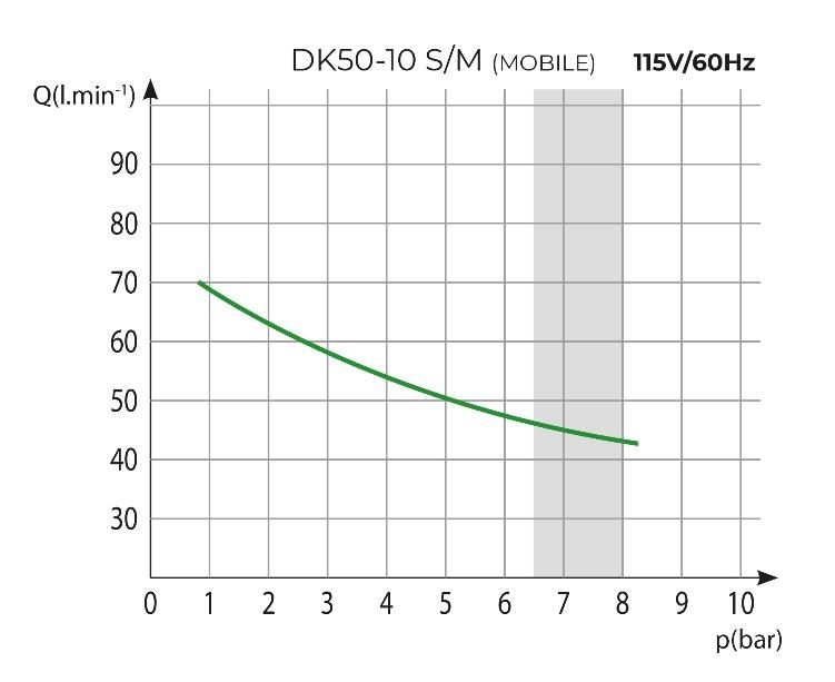
GENERAL INFORMATION

          Package handling label – this side up

          Package handling label – keep dry

          Package handling label – temperature limits

          Package handling label – limited stacking

          Package label – recyclable material

          Manufacturer

3. DEVICE USE

   3.1.   Intended use
The compressor is used as source of clean oil-free compressed air intended to be used in industry
and laboratories, where parameters and properties of the compressed air are suitable.
The compressor is exclusively intended to compress air without content of explosive or chemically
unstable substances.
The compressor is intended for operation in clean and dry rooms

   3.2.   Incorrect use
          Contamination risk.
          Air from the compressor is without additional treatment not suitable for breathing
          and direct contact with food

          Explosion risk.
          The product is not intended for operation in rooms with explosion risk.
The compressor must not be used to compress aggressive gases.
The compressor must not be operated in premises with occurrence of flammable vapors.
The compressor must not be operated in other conditions as mentioned in Technical data.
Any other use of the product beyond the intended use is considered as incorrect use. The
manufacturer is not responsible for any damages or injuries as a result of incorrect use or
disobedience to instructions stated in this User manual. All risks shall be solely borne by the
user/operator.

03/2020                                         7                        NP-DK50-10SM-5_03-2020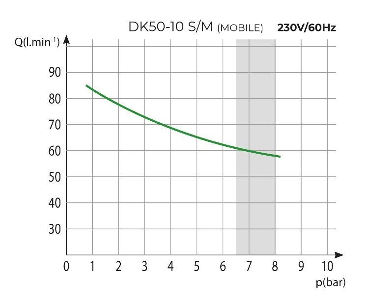
GENERAL INFORMATION
4. GENERAL SAFETY INSTRUCTION
The product is designed and manufactured so that any risks connected with its use are minimized
and the product is safe for the user and surrounding when used according to the intended use and
the instructions stated below are followed.
4.1. Required qualification of the personnel
Each user must be trained by the manufacturer or an organization authorized by the
manufacturer or instructed on the device operation by other trained user.
Installation, new settings, changes, extensions and repairs of the product may be
performed by the manufacturer or an organization authorized by the manufacturer
(hereinafter qualified technician).
- Otherwise the manufacturer is not responsible for safety, reliability and correct functioning
of the product.
4.2. General instructions
When operating the compressor, all acts and local regulations valid in the place of use
must be observed. The operator and user are responsible for following the applicable
regulations.
Before every use, the user must check, if the device is functioning correctly and safely.
Before building the compressor in other devices, the supplier must assess, if the supplied
air and construction of the device comply with the requirements of the specified intended
use. Taking this into account, follow the product technical data. Assessment of conformity
shall be performed by the manufacturer – supplier of the final product.
4.3. Protection from dangerous voltage and pressure
The device can be connected only to a properly mounted socket with protective earthing.
Before connecting the product, check if mains voltage and mains frequency stated on the
product are in compliance with the values of the mains.
Before putting the product into operation, check eventual damages to connected
pneumatic hoses and electrical cables. Replace damaged pneumatic hoses and electrical
cables immediately.
Immediately disconnect the product from the mains (pull out the mains plug) in hazardous
situations or technical disorders.
Safety valve settings must not be changed and used to depressurize the air tank.
4.4. Original spare parts and accessories
Safety of operating staff and failure-free operation of the product are guaranteed only when
original spare parts are used. Only accessories and spare parts stated in the technical
documentation or expressly approved by the manufacturer may be used.
The guarantee does not apply to damages arising from use of accessories and spare parts
other than prescribed or recommended by the manufacturer and the manufacture is not
responsible for them.
NP-DK50-10SM-5_03-2020 8 03/2020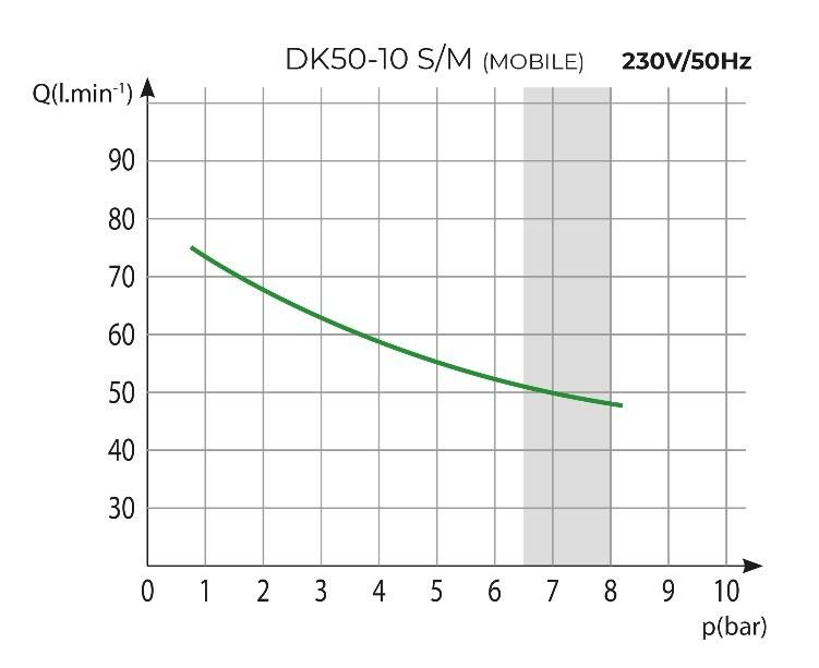
GENERAL INFORMATION

5. STORAGE AND TRANSPORT CONDITIONS
The manufacturer ships the compressor in a transport packaging. This protects the device from
damage during transport.
          Risk of damage to pneumatic parts.
          The compressor may be transported only depressurized. Vent air pressure from
          the pressure tank and pressure hoses and drain condensate from the air tank
          before transporting the compressor.

          Original packaging must be kept for eventual return of the device. If possible,
          always use the original compressor packaging for optimal protection of the
          product. If it is necessary to return the product within the guarantee period, the
          manufacturer does not guarantee for damages caused by incorrect packaging of
          the product.

          Transport the compressor in an upright position, always secured by transport
          fixing elements.

          Protect the compressor from high humidity, dirt and extreme temperatures during
          transport and storage. Do not store together with volatile chemical substances.

          If it is not possible to keep the original packaging, dispose of the packaging in an
          environmentally friendly way. Transport cardboard can be recycled with old paper.

          It is not permitted to store and transport the device outside the defined
          conditions, see below.

   5.1.   Ambient conditions
Products can be stored in rooms and means of transport that are free from any traces of volatile
chemical substances under the following climatic conditions:
 Temperature                                         from –25°C o +55°C, in 24h to +70°C
                                                     max. 90% (without condensation/ non-
 Relative humidity
                                                                condensing)

03/2020                                     9                            NP-DK50-10SM-5_03-2020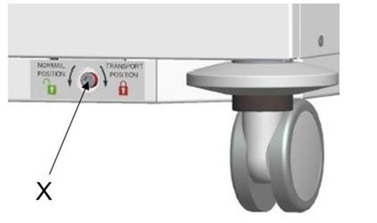
PRODUCT DESCRIPTION
PRODUCT DESCRIPTION
6. VARIANTS
The compressor is manufactured according to its intended application in the following variants:
DK50-10S/M Compressor with membrane air dryer in a compact mobile cabinet.
DK50-10S/M
The compressed air from a compressor is not suitable for the operation of
breathing appliances or similar equipment
7. PRODUCT FUNCTION
7.1. Compressor with membrane dryer
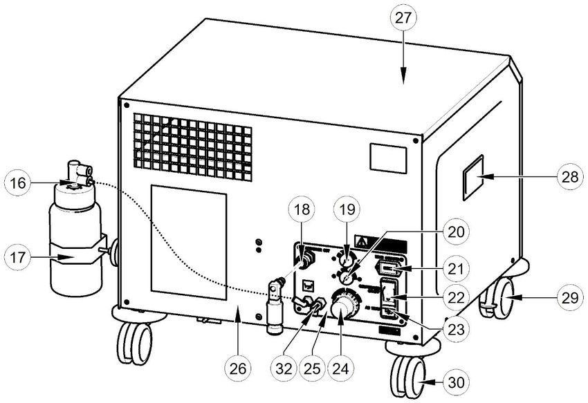
Fig. 2 The compressor aggregate (1) draws in air through an inlet filter (7) and compresses it,
feeding it to the cooler (10) through the filter (8) and the non-return valve (3) into the dryer (9), and
feeds the clean and dry air into the air tank (2). The connected apparatus draws the compressed
air from the air tank until the pressure drops to a default preset level on the air-pressure switch (4)
switching the compressor on. The compressor again compresses air into the nozzle until the
maximum pressure is reached and the compressor switches off. The pressure hose is vented
through the relief solenoid valve (12) once the compressor unit is shut off. The safety valve (5)
prevents the pressure in the air tank from rising above the maximum allowed value. The air tank
pressure gauge (19) displays the current level of pressure in the air tank.
The dryer ensures the continuous drying of the compressed air. Condensate from the filter is
automatically released into a condensate collection vessel (16). Constant output pressure is
maintained by the pressure regulator (24). The pressure is displayed on the pressure gauge
regulator (20). The power switch (22), connector (23), hour counter (21) and compressed air outlet
connector (18) are installed on the outlet panel (25).
7.2. Compressor cabinet
Fig. 1, Fig. 2 The cabinet is compact and soundproof, while the fan (15) under the compressor
aggregate and the cooler fan allow the sufficient exchange of cooling air. The fans also operate
when the compressor motor is running or when the temperature in the cabinet rises above 40°C.
The fans automatically switch off once the space in the cabinet is cooled to below 32°C. The
compressor is equipped with 2 casters with brakes (29) in front and 2 casters without brakes (30)
NP-DK50-10SM-5_03-2020 10 03/2020PRODUCT DESCRIPTION
in the back. They can be replaced by packaged rubber feet.
The main switch is located on the front face of the cabinet (31).
Risk of compressor overheating.
Make sure that there are no obstacles at the cooling air inlet into the cabinet
(around the bottom part of the cabinet) and at the hot air outlet on the top back
side of the cabinet.
If the compressor is placed on a soft floor, e.g. carpet, create space between
the base and the floor or the cabinet and the floor, e.g. underlay the footings
with hard pads to ensure sufficient cooling of the compressor.
Description to Figures 1-2:
1 Air pump
18 Compressed air outlet
2 Air tank
19 Air tank pressure gauge
3 Non-return valve
20 Regulator pressure gauge
4 Pressure switch
21 Hour counter
5 Safety valve
22 Power switch
7 Inlet filter
23 Connector
8 Dryer filter
24 Pressure regulator
9 Dryer
25 Outlet panel
10 Cooler
26 Rear panel
11 Automatic condensate drain
27 Cabinet cover
12 Relief valve
28 Compressor handle
13 Screw
29 Caster with brake
14 Fan housing
30 Caster
15 Fan
31 Main switch
16 Condensate collection vessel
32 Drain valve c)
17 Magnetic holder
Fig. 1: DK50-10S/M – Compressor
03/2020 11 NP-DK50-10SM-5_03-2020PRODUCT DESCRIPTION Fig. 2: DK50-10S/M – Compressor with dryer c) Singapore certification NP-DK50-10SM-5_03-2020 12 03/2020
TECHNICAL DATA

TECHNICAL DATA

Compressors are designed to operate in dry, ventilated and indoor dust-free rooms with the
following climatic conditions:
 Temperature                                                     from +5°C to +40°C
 Relative humidity                                                    max. 70%

Working pressure 6.5 – 8.0 bar             DK50-10S/M        DK50-10S/M              DK50-10S/M c)
Nominal voltage
                            V, Hz            230, 50/60         115, 60                 230, 50
Frequency a)
Capacity at 7 bar           l/min,              50/60               45                      50
(FAD)                     (Cft./min)          (1.8/2.1)           (1.6)                   (1.8)
                             bar.             6.5 – 8.0,        6.5 – 8.0,              6.5 – 8.0,
Working pressure b)
                             (psi)          (94,3 – 116)      (94.3 – 116)            (94.3 – 116)
Max. current                  A               4.7 / 5.1          10.4                     4.7
                             kW,                0.55             0.55,                    0.55
Motor power
                             (PS)             (0.737)           (0.737)                 (0.737)
                               l,                10,              10,                      10,
Air tank volume
                             (gal)             (2.2)             (2.2)                   (2.2)
Maximum operating
                             bar,               12.0              12.0                    9.0
pressure of safety
                             (psi)             (174)             (174)                  (130.5)
valve
Noise level at 7 bar
                              dB                ≤58               ≤60                     ≤58
(LpA)
Operating mode                %               S1-100            S1-100                  S1-100
                             °C,                 3,                3,                      3,
PDP drying at 8 bar
                             (°F)              (37.4)            (37.4)                  (37.4)
Dimensions with the
                             mm            595x520x515        595x520x515             595x520x515
casters (net)
                             (in)        (23.4x20.5x20.3)   (23.4x20.5x20.3)        (23.4x20.5x20.3)
wxdxh
                              kg,               65,               65,                     65,
Net weight
                             (Ibs)             (143)             (143)                   (143)
Weight with the               kg,               66,               66,                     66,
casters                      (Ibs)             (145)             (145)                   (145)

a) State the compressor variant in the order
b) For other range of pressure consult with the supplier
c) Singapore certification

03/2020                                            13                          NP-DK50-10SM-5_03-2020
TECHNICAL DATA Dependence of compressor capacity on working pressure FAD correction of capacity for altitude Capacity given in the form of FAD („Free Air Delivery“) applies to the following conditions: Altitude 0 m.n.m. Temperature 20°C Atmospheric pressure 101325 Pa Relative humidity 0% To calculate FAD compressor capacity in dependence on altitude, it is necessary to apply correction factor according to the following table: Altitude [m.n.m.] 0 -1500 1501 - 2500 2501 - 3500 3501 - 4500 FAD correction factor 1 0,8 0,71 0,60 NP-DK50-10SM-5_03-2020 14 03/2020
INSTALLATION
INSTALLATION
Risk of incorrect installation.
Only a qualified professional can install the compressor and place it into
operation for the first time. His obligation is to train the operating personnel on
the use and maintenance of the device. He shall confirm installation and
training of operators by an entry into the installation record (see Annex).
8. INSTALLATION CONDITIONS
The compressor may only be installed and operated in dry, well-ventilated and dust-free
rooms with conditions stated in Technical data.
Risk of damage to the device.
Do not operate the device in outdoor environment or in humid or wet rooms.
Explosion risk.
Do not install the device in any rooms, in which explosive gases, dusts or
flammable liquids may be present.
The compressor must be installed in such a way, that it is accessible at all times for
operation and maintenance and label on the device is accessible.
The compressor must stand on a flat, sufficiently stable base (be aware of the compressor
weight, see chap. Technical data).
Ensure the air delivered by the compressor meets the requirements for its intended use
before installing the compressor. Refer to the technical data of the product for this purpose.
The supplier of the final product must classify and evaluate compliance with the intended
application.
Any other use or use above this framework is not considered to be proper use. The
manufacturer is not responsible for damages that arise from such use. The operator/user
assumes all risk.
Cabinet-mounted compressors can only be operated in areas with continuous
air circulation and away from any sources of heat or direct exposure to
sunlight.
Risk of damage to the device.
The equipment must be located at least 100 mm from a wall in order to ensure
proper cooling air circulation. Failure to comply with such spacing may cause
damage to the compressor and cabinet!
9. COMPRESSOR ASSEMBLY
Unpack the compressor from the packaging.
9.1. Manipulation and fixation removal
Put the compressor at the place of operation
Use a hex key to rotate the stabilizer screw (X) down to the stop to the position - the
air pump will reach the operating position (Fig. 3).
03/2020 15 NP-DK50-10SM-5_03-2020INSTALLATION
Fig. 3: Fixation removal
Operating position
Prior to installation, ensure that the air pump is free of transport packaging and
stabilizers to avoid any risk of damage to the product.
9.2. Caster installation
The manufacturer delivers the product with casters installed. If the user has previously
installed feet, install the casters as follows
Fig. 4: Caster installation
NP-DK50-10SM-5_03-2020 16 03/2020INSTALLATION Fig. 5: Setting the brakes The compressor may be secured against moving - Lock the casters! 9.3. Installing feet If using the product on rubber feet is acceptable, continue as follows Fig. 6: Installing feet 10. PNEUMATIC CONNECTION 10.1. Connecting to the compressed air outlet Fig. 7: Compressed air outlet Connect a pressure hose to the compressed air quick connector (1). 03/2020 17 NP-DK50-10SM-5_03-2020
INSTALLATION
11. ELECTRICAL CONNECTION
11.1. Electrical connection
Risk of electric shock.
Connect the mains power cord to the compressor connector. The compressor
is equipped with a DF11 mains power module, which contains an IEC C14
power connector with a thermal fuse and the mains switch. Make sure this
connection complies with local electrical codes. The mains voltage and
frequency must comply with the data stated on the equipment's label.
The D11 fuse and switch module must be kept in an easily accessible location in case the
equipment has to be safely shut down in an emergency.
The connection to the power distribution box must be limited by a current protection device
at max. 16 A.
Risk of fire and electric shock.
The electrical cord cannot touch any hot parts of the compressor. It may
damage the insulation!
Risk of fire and electric shock.
If any electrical cord or air hose is damaged it must be replaced immediately
The equipment is equipped with C14 power connector with the V-lock system.
The C13 plug may also be equipped with the V-Lock system, which protects the
compressor and mains plug from coming loose unexpectedly.
11.2. Grounding instructions
The product connects to the mains with a grounded plug. The power-supply cord and its
plug may be connected only to a properly installed and grounded socket in accordance
with all local laws and regulations.
Risk of electric shock.
A faulty power-supply cord with a plug or a faulty socket may lead to the risk of
electric shock.
If you have any doubts about the product’s proper connection to the mains,
consult a qualified electrician or service technician. Do not modify the original
socket! Contact a qualified electrician.
Only power-supply cord (included in the packaging) with a matching line-
voltage configuration may be connected to the compressor power inlet. The
mains voltage and frequency must comply with the data stated on the device’s
label.
11.3. Connecting the product to the mains
The compressor connects to the mains using a power-supply cord (included in the packaging) that
has a product-side IEC60320 C13 socket and a mains-side plug in compliance with the standards
of the country of the intended use of the product (e.g. CEE(7) VII / C13).
The power-supply cord with a socket and plug is designed for the current and voltage levels of the
rated current and voltage of the product. The minimum cross-section of the bare conductors of the
cord is 0.75 mm2.
NP-DK50-10SM-5_03-2020 18 03/2020INSTALLATION
12. FIRST OPERATION
Check whether the compressor has been set to the operating position (Fig. 3)
Check that all compressed air line connections are secure. (see chapter 10)
Ensure electrical connections are secure and properly completed. (see chapter 11)
12.1. Switch on the compressor
Turn the power switch (22) into the “I” position on the rear side of the compressor (Fig. 1)
and the main switch (31) on the front face of the cabinet (Fig. 2)
Compressor - At first operation the air tank is pressurized until it reaches a presets level when the
compressor automatically switches off. As the air is used, the compressor works in automatic
mode, switched on or off by the pressure switch. During operation, the air dryer removes humidity
from the supplied compressed air.
The compressor is not equipped with an emergency power supply.
13. ELECTRICAL DIAGRAMS
DK50-10S/M 6.5 – 8 bar
1/N/PE 230 V, 50/60 Hz
ELEKTRICAL OBJECT OF 1st. CAT.
03/2020 19 NP-DK50-10SM-5_03-2020INSTALLATION DK50-10S/M 6.5 – 8 bar 1/N/PE 115 V, 60 Hz ELEKTRICAL OBJECT OF 1st. CAT. Description to electrical diagrams: M1 Compressor motor Q2 Main switch E1 Compressor fan C1 Capacitor E2 Dryer fan B1 Pressure switch M2 Relief valve X1 Terminal box B2 Temperature switch M4 Automatic condensate drain Q1 Thermal breaker P1 Hour counter NP-DK50-10SM-5_03-2020 20 03/2020
INSTALLATION

14. PNEUMATIC DIAGRAM
DK50-10S/M

Description to pneumatic diagram:
                                             10   Safety valve
      1   Inlet filter
                                             11   Pressure switch
      2   Compressor fan
                                             12   Air tank
      3   Air pump
                                             13   Regulator
      4   Fan
                                             14   Filter
      5   Cooler
                                             15   Noise silencer
      6   Dryer
                                             16   Pressure gauge of air tank
      7   Relief valve
                                             17   Automatic condensate drain
      8   Non-return valve
                                             18   Condensate collection vessel
      9   Pressure gauge of regulator
                                             19   Drain valve c)
c)
     Singapore certification

03/2020                                 21                       NP-DK50-10SM-5_03-2020
OPERATION
OPERATION
THE EQUIPMENT MAY ONLY BE OPERATED BY THE TRAINED STAFF!
Risk of electric shock.
In case of emergency, disconnect the compressor from the mains (pull out the
mains plug).
Risk of burn or fire
During compressor operation, the pump parts may heat to temperatures
dangerous for contact with persons or materials.
Warning – compressor is controlled automatically.
Automatic start-up. When pressure in the pressure tank drops to switch-on
pressure, the compressor automatically switches on. The compressor
automatically switches off, when pressure in the air tank reaches the switch-off
pressure.
Hazard of damage to dyer.
When the dryer is operated at ambient temperature that is higher than
maximum operating temperature stated in Technical data, the dryer can be
damaged
During longer operation of the compressor, the temperature in the surrounding
of the compressor increases above 40 °C and the cooling fan switches on
automatically. After cooling the space below 32 °C, the fan switches off.
15. SWITCHING ON THE COMPRESSOR
Switch the power switch (22) to the "I" position and the main switch (31) to the „ON“
position. The compressor sends pressurized air to the air tank. As the compressed air is
used, the pressure in the air nozzle drops to a preset level, the compressor switches on
and the air nozzle files with compressed air. After reaching the cutoff pressure the
compressor turns off automatically and the cycle is repeated. Do not exceed the maximum
operating pressure marked on the air tank pressure gauge (19). The preset switching-off
pressure can vary within the range of i 10%.
Risk of damage to pneumatic parts.
Never tamper with the pressure switch. Adjustments are not allowed. The
pressure switch (4) has been set by the manufacturer and further setting of
switching on and off pressure may be carried out only by a qualified expert
trained by the manufacturer.
NP-DK50-10SM-5_03-2020 22 03/2020PRODUCT MAINTENANCE
PRODUCT MAINTENANCE
16. PRODUCT MAINTENANCE
The operator should carry out device checks regularly in the intervals defined
by applicable regulations. Test results must be recorded.
Risk of servicing by persons without required qualification.
Repair works beyond standard maintenance (see chapter 16.1 - Maintenance
intervals) may only be performed by a qualified technician (organization
authorized by the manufacturer) or manufacturer’s customer service.
Standard maintenance works (see Chapter 16.1 - Maintenance intervals) may
only be carried out by a trained operator.
Only use spare parts and accessories approved by the manufacturer.
The device has been designed and manufactured to keep its maintenance to a minimum. For
correct and reliable operation of the compressor perform the following operations.
Risk of injury and damage to the device.
Before any maintenance work, it is necessary to:
- check, if it is possible to disconnect compressor from the supplied
equipment, so that there is no risk of damage to a person using the given
appliance or any other material damages
- switch off the compressor
- disconnect it from the mains (pull out the mains plug)
- vent the compressed air from the air tank
Risk of injury when venting the compressed air.
Protect eyesight – wear goggles when venting the compressed air from the
compressor pneumatic system (air tank).
Risk of burn.
Pump components (head, cylinder, and pressure hose) have high temperature
during and shortly after compressor operation – do not touch these
components!
Let the device cool before any product maintenance, service or connection/
disconnection of pressurized air!
03/2020 23 NP-DK50-10SM-5_03-2020once
once a once a Performed
Time interval every 2 Chap. Spare parts set
week year by
years
Cleaning the product x 16.2 -
Drain condensate from the vessel x 16.3 -
operator
NP-DK50-10SM-5_03-2020
Replacement of filter element x 16.4 025200304-000
Check of safety valve x 16.5 -
16.1. Maintenance intervals
Replacement of inlet filter x 16.6 025200126-000
Check of fan and cooler x 16.7 -
24
qualified technician
Check of pneumatic connection Service
x -
leakage and device inspection documentation
03/2020
PRODUCT MAINTENANCEPRODUCT MAINTENANCE
To ensure that the compressor works correctly, perform the following maintenance tasks at regular
intervals.
16.2. Cleaning the product
Clean the product using regular detergents or an alcohol-based cleaner. The product cannot be
cleaned using any substances containing an abrasive substance, chemical solvents or other
aggressive substances.
16.3. Draining condensate from the vessel
During standard operation, the condensate is captured in the filter and subsequently automatically
released into the condensate vessel. Remove the vessel from its holder, loosen the cap and drain
the condensate at the defined intervals. Then close the vessel and place it back.
Risk of slipping on a wet floor in case of the collecting vessel overflow.
Monitor the level in the vessel using the markings and empty at least once a
day.
16.4. Replacement of filter element in filter
Disassemble the cabinet cover before replacing the filter element. The earthing cable must be
disconnected after partially removing the cabinet cover (See chap. 16.9).
Remove the hose (1) from the quick connector.
Use a wrench (2) to release the filter vessel (3) and remove.
Pull down on the filter element (4) to remove.
Insert a new filter element.
Re-install the filter vessel.
Gently tighten the filter vessel with the wrench.
Install the hose back on the quick connector
Connect the earthing cable to the cabinet cover and install the cabinet cover.
03/2020 25 NP-DK50-10SM-5_03-2020PRODUCT MAINTENANCE
Fig. 8: Replacement of filter element in filter
Filter Article no. Filter element Article no.
AF0056 025200303-000 CARTRIDGE 06050 025200304-000
16.5. Check of safety valve
Disassemble the cabinet cover before the safety valve check and reassemble it afterwards. (see
chap.16.9)
When the compressor is operated for the first
time, make sure that the safety valve is working
properly.
Turn screw of safety valve several
rotations to the left until the safety valve
releases air.
Let the safety valve blow out for only a
few seconds.
Turn screw to the right until it seats,
closing the valve.
Fig. 9: Check of safety valve
Risk of pressure increase when safety valve is damaged.
Safety valve must not be used to depressurize the air tank. It could damage the
safety valve function. The valve is set to the maximum allowed pressure, it is
tested and marked.
Safety valve setting must not be adjusted.
Risk of injury when compressed air is vented.
Protect your eyesight when checking the safety valve – wear protective
goggles.
NP-DK50-10SM-5_03-2020 26 03/2020PRODUCT MAINTENANCE
16.6. Replacement of inlet filter
Pull out the rubber plug (2) by hand.
Remove the dirty inlet filter (1).
Insert a new filter and mount the rubber plug.
Fig. 10: Replacement of inlet filter
Disassemble the cabinet cover before replacing the input filter element and reassemble it
afterwards. (See chap.16.9)
16.7. Check of fan and cooler
The equipment, in particular the compressor fan, cooler fan, and the cooler (10), must be kept
clean to ensure efficient drying. Remove dust from surface of the fan or cooling fins by vacuuming
or blowing down with compressed air.
16.8. Removal and installing of the rear panel (qualified technician)
Fig. 11.: Removal of rear panel
The rear panel must be removed and the grounding wire must be disconnected from the
rear panel before any of the following checks
03/2020 27 NP-DK50-10SM-5_03-2020PRODUCT MAINTENANCE
Installing rear panel
Fig. 12: Installing rear panel
The grounding wire from the compressor base must be connected before reassembling the
rear panel
16.9. Removal and installing of cabinet cover
The cabinet cover must be removed and the grounding wire must be disconnected before
any of the following checks
Fig. 13: Removal of cabinet cover
NP-DK50-10SM-5_03-2020 28 03/2020PRODUCT MAINTENANCE
Installing cabinet cover
Fig. 14: Installing cabinet cover
The grounding wire from the compressor base must be connected before reassembling the
cover
16.10. Setting outlet air pressure
To unlock the control button of the regulator,
raise it slightly and rotate it to set the demand
outlet pressure.
Monitor the pressure gauge (20).
After setting the pressure, lock the control
button of the regulator by pushing it down.
Fig. 15: Setting outlet air pressure
16.11. Fixation the equipment before transport
The equipment must be secured before any type of transport.
Rotate the stabilizer screw (X) (Fig. 3) down to the stop to the - the air pump will reach
the transport position (Fig. 16).
Fig. 16: Transport position
03/2020 29 NP-DK50-10SM-5_03-2020TROUBLESHOOTING
17. LONG-TERM SHUTDOWN
If the compressor will not be used for an extended period of time, then the main switch (31) on the
compressor and the power switch on the rear side (22) must be switched off and the device must
be disconnected from the mains. (Fig. 1, Fig. 2).
18. DISPOSAL OF DEVICE
Disconnect the appliance from the mains.
Release air pressure in pressure tank by opening the valve on the appliance.
Liquidate the appliance according to local valid regulations.
Order the sorting and liquidation of waste in specialized organization.
Dispose of the appliance following all environmental regulations.
TROUBLESHOOTING
Risk of electric shock.
Before any of the following operations on the device, disconnect the device
from the mains (pull out the mains plug).
Risk of injury during work with pneumatic components under pressure.
Before any of the following operations on the device, it is necessary to
decrease pressure in the air tank and in the pneumatic system to zero.
Any operations concerning the troubleshooting may be performed only by
a qualified technician.
Malfunction Possible cause Solution
Check voltage in socket
Check circuit breaker switch –
switch to position switched-on „I“
Check the main switch - switch into
No voltage in the pressure switch the “ON” on position
Loose conductor from terminal -
Compressor does repair
not switch on Check electrical cord – replace
defective cord
Motor winding failure, damaged
Replace motor or windings
thermal protection
Capacitor failure Replace capacitor
Seized piston or other rotating part Replace damaged components
Pressure switch does not switch Check function of pressure switch
Check pneumatic system – seal
Air leakage in pneumatic system
Compressor often loose connections
switches on Clean non-return valve, replace
Non-return valve (SV) leakage
seals, replace non-return valve
NP-DK50-10SM-5_03-2020 30 03/2020TROUBLESHOOTING
Large volume of condensed liquid in
Drain condensed liquid
pressure tank
Low compressor capacity Check time of filling the air tank
Check pneumatic system – seal
Air leakage in pneumatic system
loose connection
Prolonged
operation of the Worn piston ring Replace worn piston ring
compressor Dirty inlet filter Replace dirty filter with new filter
Plugged filter element Replace with new filter element
Dryer does not dry
(condensed water Dirty filter Replace dirty filter with new filter
in the air) *
)* Clean inside surfaces of the air tank thoroughly and remove all condensed liquid after dryer
failure.
To protect the connected equipment from any damage, it is necessary to check
humidity of the released air from the air tank (see chapter Technical data)
19. REPAIR SERVCE
Guarantee and post-guarantee repairs are provided by the manufacturer or organizations and
technicians approved by the manufacturer.
Warning
The manufacturer reserves the right to make changes on the device, which will not significantly
affect properties of the device.
03/2020 31 NP-DK50-10SM-5_03-2020INHALT
INHALT
ALLGEMEINE INFORMATIONEN ...............................................................................................33
1. KONFORMITÄT MIT DEN ANFORDERUNGEN DER EU ..............................................33
2. SYMBOLE ......................................................................................................................33
3. NUTZUNG DES GERÄTS ..............................................................................................34
4. ALLGEMEINE SICHERHEITSANWEISUNGEN .............................................................35
5. LAGERUNGS- UND TRANSPORTBEDINGUNGEN ......................................................36
PRODUKTSCHREIBUNG ............................................................................................................37
6. MODELLE ......................................................................................................................37
7. PRODUKTFUNKTION....................................................................................................37
TECHNISCHE DATEN .................................................................................................................41
INSTALLATION ...........................................................................................................................43
8. INSTALLATIONSBEDINGUNGEN .................................................................................43
9. ZUSAMMENBAU DES KOMPRESSORS .......................................................................43
10. PNEUMATISCHER ANSCHLUSS ..................................................................................45
11. ELEKTRISCHER ANSCHLUSS .....................................................................................46
12. INBETRIEBNAHME........................................................................................................47
13. ELEKTROSCHALTPLAN ...............................................................................................48
14. PNEUMATISCHES SCHEMA ........................................................................................49
BETRIEB......................................................................................................................................49
15. EINSCHALTEN DES KOMPRESSOR ............................................................................50
PRODUKTWARTUNG .................................................................................................................51
16. PRODUKTWARTUNG ...................................................................................................51
17. LANGFRISTIGE AUßERBETRIEBNAHME ....................................................................58
18. ENTSORGUNG DES GERÄTS ......................................................................................58
FEHLERBEHEBUNG ...................................................................................................................58
19. INFORMATIONEN ZU REPARATURBETRIEBEN .........................................................59
ANHANG......................................................................................................................................87
21. INSTALLATIONSPROTOKOLL ......................................................................................88
NP-DK50-10SM-5_03-2020 32 03/2020ALLGEMEINE INFORMATIONEN
ALLGEMEINE INFORMATIONEN
Lesen Sie das Benutzerhandbuch vor der Nutzung des Produkts sorgfältig durch und bewahren
Sie es auf. Das Benutzerhandbuch enthält Anleitungen zur korrekten Nutzung, Installation,
Bedienung und Wartung des Produkts.
Zum Zeitpunkt des Drucks entspricht das Benutzerhandbuch dem Produktdesign und erfüllt die
geltenden Sicherheits- und Technikstandards. Der Hersteller behält alle Rechte zum Schutz der
angeführten Verbindungen, Verfahren und Namen.
Die Originalsprache des Benutzerhandbuchs ist Slowakisch. Das Benutzerhandbuch wurde nach
bestem Wissen übersetzt. Bei Unsicherheiten gilt die slowakische Version.
1. KONFORMITÄT MIT DEN ANFORDERUNGEN DER EU
Das Produkt erfüllt die Anforderungen der Europäischen Union 2006/42/EG, 2014/29/EU,
2014/35/EU, 2014/30/EU, 2011/65/EU und ist sicher, wenn es gemäß dem Verwendungszweck
genutzt wird und alle Sicherheitsanweisungen befolgt werden.
Das Benutzerhandbuch entspricht den Anforderungen der Direktive 2006/42/EG.
2. SYMBOLE
Die folgenden Symbole und Markierungen werden in dem Benutzerhandbuch, auf dem Gerät und
auf seiner Verpackung verwendet:
Allgemeiner Warnhinweis
Achtung – Stromschlaggefahr!
Achtung – Kompressor wird automatisch gesteuert
Achtung – heiße Oberfläche
Allgemeine Warnungen
Siehe Benutzerhandbuch
Befolgen Sie das Benutzerhandbuch
CE-Kennzeichnung
Seriennummer
Schutzerdung
Sicherung
03/2020 33 NP-DK50-10SM-5_03-2020ALLGEMEINE INFORMATIONEN
Etikett für die Handhabung der Verpackung – zerbrechlich
Etikett für die Handhabung der Verpackung – diese Seite nach oben
Etikett für die Handhabung der Verpackung – trocken halten
Etikett für die Handhabung der Verpackung – Temperaturlimits
Etikett für die Handhabung der Verpackung – Stapelbeschränkung
Verpackungsetikett – recyclebares Material
Hersteller
3. NUTZUNG DES GERÄTS
3.1. Bestimmungsgemäße Nutzung
Der Kompressor wird als Quelle für saubere, ölfreie Druckluft für die Industrie und Labore dort
verwendet, wo die Parameter und Eigenschaften der Druckluft für die Nutzung geeignet sind.
Der Kompressor dient ausschließlich dazu, Luft ohne Anteile an explosiven oder chemisch
instabilen Substanzen zu komprimieren.
Der Kompressor ist für den Betrieb in sauberen und trockenen Räumen konzipiert.
3.2. Unsachgemäße Nutzung
Kontaminationsrisiko.
Die Luft aus dem Kompressor ist ohne zusätzliche Behandlung nicht für das
Einatmen und den direkten Kontakt mit Lebensmitteln geeignet.
Explosionsrisiko.
Das Produkt ist nicht für den Betrieb in Räumen mit Explosionsrisiko geeignet.
Der Kompressor darf nicht für das Komprimieren von aggressiven Gasen verwendet werden.
Der Kompressor darf nicht in Umgebungen verwendet werden, in denen es entflammbare Dämpfe
gibt.
Der Kompressor darf nur unter den Bedingungen verwendet werden, die im Abschnitt Technische
Daten aufgeführt sind.
Jegliche andere Nutzung des Produkts über die bestimmungsgemäße Verwendung hinaus gilt als
unsachgemäße Nutzung. Der Hersteller haftet nicht für Schäden oder Verletzungen aufgrund
einer unsachgemäßen Nutzung oder Nichtbeachtung der Anweisungen in diesem
Benutzerhandbuch. Einzig der Benutzer/Bediener trägt alle Risiken.
NP-DK50-10SM-5_03-2020 34 03/2020ALLGEMEINE INFORMATIONEN
4. ALLGEMEINE SICHERHEITSANWEISUNGEN
Das Produkt wurde entwickelt und hergestellt, um alle Risiken in Verbindung mit seiner Nutzung
zu minimieren. Das Produkt ist für den Benutzer und für die Umgebung sicher, wenn es gemäß
seinem Verwendungszweck und den nachfolgend aufgeführten Anweisungen verwendet wird.
4.1. Erforderliche Qualifikation der Mitarbeiter
Alle Benutzer müssen durch den Hersteller oder durch einen von dem Hersteller
autorisierten Dienstleister geschult oder durch einen weiteren geschulten Bediener in der
Nutzung des Geräts unterwiesen werden.
Montage, Neueinstellungen, Änderungen, Erweiterungen und Reparaturen des Produkts
müssen durch den Hersteller oder von einem durch den Hersteller autorisierten
Dienstleister (hierunter qualifizierter Techniker) erfolgen.
- Andernfalls übernimmt der Hersteller keine Verantwortung für die Sicherheit,
Zuverlässigkeit und korrekte Funktion des Produkts.
4.2. Allgemeine Anweisungen
Bei der Nutzung des Kompressors müssen alle relevanten Gesetze und lokalen
Vorschriften am Einsatzort beachtet werden. Der Bediener und der Benutzer sind für die
Einhaltung der geltenden Vorschriften zuständig.
Vor jeder Nutzung muss der Benutzer prüfen, ob das Gerät korrekt und sicher funktioniert.
Vor dem Einbau des Kompressors in andere Geräte muss der Lieferant prüfen, ob die
zugeführte Luft und die Bauart des Geräts den Anforderungen des festgelegten
Verwendungszwecks entsprechen. Beachten Sie hierzu die Technischen Daten für das
Produkt. Der Hersteller – der Lieferanten des Endprodukts hat die Konformitätsprüfung
vorzunehmen.
4.3. Schutz vor gefährlicher Spannung und Druck
Das Gerät darf nur an eine korrekt montierte Steckdose mit Schutzerdung angeschlossen
werden.
Überprüfen Sie vor dem Anschluss des Produkts, ob die auf dem Produkt angegebene
Netzspannung und Netzfrequenz mit den Werten des Versorgungsnetzes übereinstimmen.
Überprüfen Sie vor der Inbetriebnahme des Produkts die angeschlossenen
Druckluftschläuche und Stromkabel auf Beschädigungen. Beschädigte Druckluftschläuche
und Stromkabel sind unverzüglich zu ersetzen.
Trennen Sie das Produkt in gefährlichen Situationen oder bei technischen Störungen
sofort vom Stromnetz (den Netzstecker ziehen).
Die Einstellungen der Sicherheitsventile dürfen nicht geändert und nicht für die
Druckluftentlastung des Druckluftbehälters verwendet werden.
4.4. Original-Ersatzteile und –Zubehörteile
Die Sicherheit des Bedienpersonals und der störungsfreie Betrieb des Produkts sind nur
bei Verwendung von Original-Ersatzteilen garantiert. Es dürfen nur Zubehör- und
Ersatzteile verwendet werden, die in der technischen Dokumentation angegeben oder
ausdrücklich vom Hersteller zugelassen sind.
Die Garantie gilt nicht für Schäden aufgrund der Verwendung von Zubehörteilen und
Ersatzteilen, die nicht durch den Hersteller vorgeschrieben oder empfohlen wurden. Der
Hersteller übernimmt hierfür keine Haftung.
03/2020 35 NP-DK50-10SM-5_03-2020ALLGEMEINE INFORMATIONEN
5. LAGERUNGS- UND TRANSPORTBEDINGUNGEN
Der Hersteller versendet den Kompressor in einer Transportverpackung. Diese schützt das Gerät
während des Transports vor Schäden.
Beschädigungsgefahr für Pneumatikteile.
Der Kompressor darf nur drucklos transportiert werden. Lassen Sie die Druckluft
aus dem Druckluftbehälter und den Druckluftschläuchen ab und entleeren Sie
das Kondensat aus dem Druckluftbehälter, bevor Sie den Kompressor
transportieren.
Die Originalverpackung muss für die eventuelle Rücksendung des Geräts
aufbewahrt werden. Falls möglich, verwenden Sie stets die Originalverpackung
des Kompressors, um das Produkt bestmöglich zu schützen. Muss das Produkt
während der Garantiezeit eingesendet werden, haftet der Hersteller nicht für
Schäden, die auf eine falsche Verpackung zurückzuführen sind.
Transportieren Sie den Kompressor in aufrechter Position und grundsätzlich mit
Transportsicherung.
Während des Transports und der Lagerung ist der Kompressor vor hoher Feuchtigkeit,
vor Verunreinigungen und extremen Temperaturen zu schützen. Nicht in der Nähe von
flüchtigen chemischen Substanzen lagern.
Ist eine Lagerung der Originalverpackung nicht möglich, entsorgen Sie diese
umweltgerecht. Der Transportkarton kann als Altpapier recycelt werden.
Es ist nicht zulässig, das Gerät außerhalb der angegebenen Bedingungen zu lagern
und zu transportieren; siehe unten.
5.1. Umgebungsbedingungen
Produkte können in Räumen und Transportmitteln gelagert werden, in denen keine Spuren
flüchtiger chemischer Substanzen vorhanden sind und die die folgenden klimatischen
Bedingungen erfüllen:
Temperatur von -25 °C bis +55 °C, in 24 Std. bis zu +70 °C
Max. 90 % (ohne Kondensat, nicht
Relative Feuchtigkeit
kondensierend)
NP-DK50-10SM-5_03-2020 36 03/2020PRODUKTSCHREIBUNG
PRODUKTSCHREIBUNG
6. MODELLE
Der Kompressor wurde gemäß seinem Verwendungszweck in den folgenden Modellen erbaut:
Kompressor mit Membrantrockner in einem kompakten, mobilen
DK50-10S/M
Gehäuse.
DK50-10S/M
Kompressordruckluft ist nicht geeignet für den Betrieb von Atemgeräten oder
ähnlichen Geräten.
7. PRODUKTFUNKTION
7.1. Kompressor mit Membrantrockner
Abb. 2 Das Kompressorpumpe (1) zieht Außenluft durch einen Ansaugfilter (7) ein und
komprimiert sie. Dann wird die Luft zum Kühler (10) durch den Filter (8) und das Rückschlagventil
(3) zum Trockner (9) gespeist, anschließend wird die trockene und saubere Luft in den
Druckluftbehälter (2) eingespeist. Die Pressluft wird vom Luftbehälter durch ein angeschlossenes
Gerät abgesaugt, der Luftdruck sinkt dadurch bis zu dem am Druckschalter (4) eingestellten
Schaltdruck ab, durch den der Kompressor wieder eingeschaltet wird. Der Kompressor drückt
erneut Luft bis zum Schaltdruck in die Düse, bis der Maximaldruck erreicht ist, und schaltet sich
anschließend ab. Der Druckschlauch wird durch das Ablassmagnetventil (12) entlüftet, sobald der
Kompressor abgeschaltet ist. Das Sicherheitsventil (5) verhindert, dass der Druck im Luftbehälter
über den maximal zulässigen Wert hinaus ansteigt. Der Druckmesser (19) des Luftbehälters zeigt
den aktuellen Stand des Drucks im Luftbehälter an.
Der Trockner gewährleistet eine kontinuierliche Trocknung der Druckluft. Kondensat aus dem
Filter wird automatisch in einen Kondensatauffangbehälter (16) geleitet. Der Druckregler (24) sorgt
dafür, dass der Ausgangsdruck konstant bleibt. Der Druck wird auf dem Druckmesserregler (20)
angezeigt. Der Netzschalter (22), der Netzsteckeranschluss (23), der Stundenzähler (21) und der
Ablassanschluss für die Druckluft (18) sind auf der Ablaufkonsole installiert (25).
7.2. Kompressorgehäuse
Abb. 1, Abb. 2 Das Gehäuse ist kompakt und schalldicht, während der Lüfter (15) unter dem
Kompressoraggregat und der Kühllüfter für einen ausreichenden Austausch von Kühlluft sorgen.
03/2020 37 NP-DK50-10SM-5_03-2020PRODUKTSCHREIBUNG
Die Lüfter laufen auch, wenn der Kompressormotor läuft oder wenn die Temperatur im Gehäuse
auf mehr als 40 °C ansteigt. Die Lüfter schalten sich automatisch ab, sobald der Raum im
Gehäuse auf unter 32 °C abgekühlt ist. Der Kompressor wird mit 2 Laufrollen mit Bremsen (29)
vorne und 2 Laufrollen ohne Bremsen (30) hinten geliefert. Diese können durch Gummifüße
ersetzt werden, die im Set geliefert werden.
Der Hauptschalter befindet sich an der Gehäusevorderseite (31).
Überhitzungsgefahr des Kompressors.
Stellen Sie sicher, dass keine Blockaden am Einlass der Kühlluft in das
Gehäuse (im Bodenbereich des Gehäuses) und am Auslass der Warmluft an der
Hinterseite des Gehäuses im oberen Bereich bestehen.
Wird der Kompressor auf eine weiche Unterlage gestellt (z.B. auf einen
Teppich), schaffen Sie einen Abstand zwischen der Basis und dem Boden oder
dem Gehäuse und dem Boden, indem die Füße z.B. auf feste Blöcke gestellt
werden. Damit wird eine ausreichende Kühlung des Kompressors
gewährleistet.
Beschreibung für Abbildungen 1-2:
1 Kompressorpumpe
18 Druckluftausgang
2 Druckluftbehälter
19 Druckmesser des Luftbehälters
3 Rückschlagventil
20 Druckmesserregler
4 Druckschalter
21 Stundenzähler
5 Sicherheitsventil
22 Netzschalter
7 Ansaugfilter
23 Netzsteckeranschluss
8 Filter
24 Druckregler
9 Trockner
25 Ablaufkonsole
10 Trocknerkühler
26 Gehäuserückwand
11 Automatischer Kondensatablauf
27 Gehäuseabdeckung
12 Entlüftungsventil
28 Kompressorgriff
13 Schraube
29 Laufrolle mit Bremse
14 Lüfterabdeckung
30 Laufrolle
15 Lüfter
31 Hauptschalter
16 Kondensatauffangbehälter
32 Ablassventil c)
17 Magnetische Halterung
NP-DK50-10SM-5_03-2020 38 03/2020PRODUKTSCHREIBUNG Abb. 1: DK50-10S/M – Kompressor 03/2020 39 NP-DK50-10SM-5_03-2020
PRODUKTSCHREIBUNG

Abb. 2: DK50-10/M – Kompressor mit Trockner

c)
     Singapur-Zertifizierung

NP-DK50-10SM-5_03-2020                 40                 03/2020
TECHNISCHE DATEN
TECHNISCHE DATEN
Die Kompressoren sind für den Betrieb in trockenen, belüfteten und staubfreien Innenräumen mit
den folgenden klimatischen Bedingungen vorgesehen:
Temperatur von +5 °C bis +40 °C
Relative Feuchtigkeit max. 70 %
Arbeitsdruck 6,5 – 8,0 bar DK50-10S/M DK50-10S/M DK50-10S/M c)
Nennspannung
V, Hz 230, 50/60 115, 60 230, 50
Frequenz a)
l/min, 50/60 45 50
Kapazität bei 7 bar (FAD)
(Cft./min) (1.8/2.1) (1.6) (1.8)
bar. 6,5 – 8,0, 6,5 – 8,0, 6,5 – 8,0,
Arbeitsdruck b)
(psi) (94,3 – 116) (94,3 – 116) (94,3 – 116)
Max. Strom A 4,7 / 5,1 10,4 4,7
kW, 0,55 0,55, 0,55
Motorleistung
(PS) (0,737) (0,737) (0,737)
l, 10, 10, 10,
Volumen Drucklufttank
(gal) (2,2) (2,2) (2,2)
Max. Betriebsdruck des bar, 12,0 12,0 9,0
Sicherheitsventil (psi) (174) (174) (130,5)
Geräuschpegel bei 7 bar
dB ≤58 ≤60 ≤58
(LpA)
Betriebsmodus % S1-100 S1-100 S1-100
3, 3, 3,
PDP-Trocknung bei 8 bar °C, °F
(37,4) (37,4) (37,4)
Abmessungen mit
mm 595x520x515 595x520x515 595x520x515
Laufrollen (netto)
(in) (23,4x20,5x20,3) (23,4x20,5x20,3) (23,4x20,5x20,3)
LxBxH
kg, 65, 65, 65,
Nettogewicht
(Ibs) (143) (143) (143)
kg, 66, 66, 66,
Nettogewicht mit Laufrollen
(Ibs) (145) (145) (145)
a) Nennen Sie das Kompressormodell in der Bestellung
b) Kontaktieren Sie für andere Druckbereiche den Lieferanten
c) Singapur-Zertifizierung
03/2020 41 NP-DK50-10SM-5_03-2020TECHNISCHE DATEN Abhängigkeit von Kompressorkapazität zum Arbeitsdruck FAD-Kapazitätskorrektur für Höhenagen Die Kapazität in Form von FAD („Free Air Delivery“, freie Druckluftversorgung) gilt für die folgenden Bedingungen: Höhenlage 0 m.n.m. Temperatur 20 °C Umgebungsdruck 101325 Pa Relative Feuchtigkeit 0% Um die FAD-Kompressorkapazität in Abhängigkeit von der Höhenlage zu berechnen, muss der Korrekturfaktor gemäß der folgenden Tabelle angewendet werden: Höhenlage [m.n.m.] 0 – 1500 1.501 – 2.500 2.501 – 3.500 3.501 – 4.500 FAD-Korrekturfaktor 1 0,8 0,71 0,60 NP-DK50-10SM-5_03-2020 42 03/2020
INSTALLATION
INSTALLATION
Risiko von Installationsfehlern.
Der Kompressor darf ausschließlich durch eine hierfür qualifizierte Fachkraft
installiert und in Betrieb genommen werden. Dieser ist verpflichtet,
professionelles Bedienpersonal bzgl. der Nutzung und Wartung des Geräts zu
schulen. Er wird die Installation sowie die Schulung der Bediener durch einen
Eintrag in das Installationsprotokoll (siehe Anhang) bestätigen.
8. INSTALLATIONSBEDINGUNGEN
Der Kompressor darf nur in trockenen, gut belüfteten und staubfreien Räumen installiert
und verwendet werden
Beschädigungsgefahr für das Gerät.
Verwenden Sie das Gerät nicht in Außenbereichen oder in feuchten oder
nassen Räumen.
Explosionsrisiko.
Installieren Sie das Gerät nicht in Räumen, in denen mit explosiven Gasen oder
entflammbaren Flüssigkeiten zu rechnen ist.
Der Kompressor muss so installiert werden, dass er jederzeit leicht für die Bedienung und
Wartung zugänglich und das Etikett am Gerät erreichbar ist.
Der Kompressor muss auf einer ebenen und ausreichend stabilen Grundlage stehen
(beachten Sie das Kompressorgewicht, siehe hierzu Technische Daten).
Vor Einbau des Kompressors in eine Einrichtung soll der Lieferant beurteilen, ob das zur
Verfügung stehendes Medium - Luft - den Betriebsforderungen und dem
Verwendungszweck der Einrichtung entspricht. Beachten Sie die technischen Vorgaben
des Produktes! Der Hersteller bzw. Lieferant des Gerätes muss bei der Aufstellung des
Gerätes eine Klassifizierung und Bewertung der Übereinstimmung des Mediums Luft
durchführen.
Eine Nutzung des Gerätes über den vorgesehenen Rahmen hinaus ist nicht zulässig. Der
Hersteller haftet nicht für daraus folgende Schäden. Das Risiko trägt ausschließlich der
Betreiber/Nutzer.
Kompressoren mit Gehäuse dürfen nur an Orten mit permanenter
Luftzirkulation und möglichst weit entfernt von Wärmequellen oder direkter
Sonneneinstrahlung betrieben werden.
Beschädigungsgefahr für das Gerät
Das Gerät muss mind. 100 mm von Wänden entfernt aufgestellt werden, damit
eine ausreichende Zirkulation der Kühlungsluft gewährleistet ist. Wird dieser
Abstand unterschritten, kann dies zu Schäden an Kompressor und Gehäuse
führen
9. ZUSAMMENBAU DES KOMPRESSORS
Packen Sie den Kompressor aus.
9.1. Handhabung und Freigabe des Kompressor
Platzieren Sie den Kompressor am Aufstellungsort
03/2020 43 NP-DK50-10SM-5_03-2020You can also read