Technopool pH-Rx - Zwembad DHZ
←
→
Page content transcription
If your browser does not render page correctly, please read the page content below

Technopool pH-Rx
                   Dosing systems for swimming pools
                    Dosieranlage für Schwimmbecken
                    Doseersysteem voor zwembaden

                              For other languages please visit:
                    http://aqua.quickris.com/adsp7000570-technopool-3/

 ENGLISH      Instruction manual                                         page 2

 DEUTSCH      Bedienungsanleitung                                        Seite 23

 NEDERLANDS   Instructiehandleiding                                      bladzijde 44

ADSP7000716              rev. 1.0                     25/01/2017                    1/64
TECHNOPOOL3                                                                                                                                                     CONTENTS

Dosing systems for swimming pools                                                                                                                                  ENGLISH

                                                                             CONTENTS
1 INTRODUCTION ................................................................................................................................................ 3
   1.1 Warnings ...................................................................................................................................................... 3
   1.2 Conformity .................................................................................................................................................... 4
   1.3 Technical features ........................................................................................................................................ 4
   1.4 Electrical features ......................................................................................................................................... 4
   1.5 Packaging content ........................................................................................................................................ 4
   2 INSTALLATION ............................................................................................................................................... 5
   2.1 Wall mounting .............................................................................................................................................. 5
   2.2 Electrical connections .................................................................................................................................. 5
      2.2.1 Main power supply................................................................................................................................. 5
      2.2.2 Temperature probe ................................................................................................................................ 5
      2.2.3 Flow signal ............................................................................................................................................. 5
      2.2.4 Dosing enabling signal (V1) .................................................................................................................. 6
      2.2.5 pH pump product level probe ................................................................................................................ 6
      2.2.6 Rx pump product level probe ................................................................................................................ 6
      2.2.7 Alarm output – 24V OUT Clamp............................................................................................................ 6
      2.2.8 Solenoid valve output – RELAY Clamp ................................................................................................ 6
      2.2.9 Pump switches ...................................................................................................................................... 6
   2.3 Hydraulic connections .................................................................................................................................. 7
      2.3.1 Assembly of the accessories ................................................................................................................. 8
3 Technopool pH-Rx MENU .................................................................................................................................. 9
   3.1 User Menu .................................................................................................................................................. 10
      3.1.1 Manual activation of pumps and solenoid valve .................................................................................. 11
   3.2 Installer menu ............................................................................................................................................. 12
      3.2.1 Password insertion .............................................................................................................................. 12
4 quick programming ........................................................................................................................................... 13
   4.1 Selection of the language of the system .................................................................................................... 13
   4.2 Setting the temperature .............................................................................................................................. 13
   4.3 Setting the pH (pump pH) .......................................................................................................................... 14
   4.4 Setting the redox (P2 pump) ...................................................................................................................... 15
   4.5 Setting the solenoid valve .......................................................................................................................... 16
   4.6 Calibration of pH electrode......................................................................................................................... 18
   4.7 Calibrating the redox electrode .................................................................................................................. 18
5 ADVANCED PROGRAMMING ......................................................................................................................... 19
   5.1 Configuration of the settings ...................................................................................................................... 19
   5.2 Restore the default parameters ................................................................................................................. 19
6 Alarms ............................................................................................................................................................... 20
   6.1 Setting the alarms ...................................................................................................................................... 20
   6.2 Alarm signal ............................................................................................................................................... 20
7 Winter pause ..................................................................................................................................................... 21
8 Operations to carry out at the beginning of the season .................................................................................... 21
9 Return to the after-sales service ....................................................................................................................... 21
10 Guarantee certificate ...................................................................................................................................... 21
11 APPENDIX 1 – Default parameters ................................................................................................................ 22

ADSP7000716                                             rev. 1.0                                        25/01/2017                                                            2/64
TECHNOPOOL3 INTRODUCTION
Dosing systems for swimming pools ENGLISH
1 INTRODUCTION
Technopool pH-Rx is an integrated system able to control two peristaltic pumps and a solenoid valve control relay,
for the automatic management of water treatment in the swimming pool.
Refer to appendix 2 for Technopool pH-Rx range.
Peristaltic pumps are controlled in the following ways:
pH Pump: for dosing the pH corrector.
The setpoint of the pH value is set to be maintained in the swimming pool.
Rx Pump: for dosing the disinfectant.
The setpoint of the redox value is set to be maintained in the swimming pool.
On the other hand, the solenoid valve of the control relay, used for dosing the chlorine tablets, can be programmed
in two ways:
cyclic
Opening (ON) and closing (OFF) schedule of the relay are fixed or proportional to the temperature of the
water reached during the latest dosing.
ON/OFF
Opening (ON) and closing (OFF) schedule is controlled by the redoxprobe; therefore, it depends on the
setpoint setting with a fixed hysteresis of 10 mV (redox).
1.1 Warnings
This manual has the purpose to provide all information required for a correct installation and maintenance of the
system, to ensure best results during its operation.
For this reason, the instructions described below must be carefully read, as they supply all information required for
the installation, use and maintenance safety.
Store this manual with care so it can be consulted when necessary.
Ensure the integrity of the system at the delivery; in case anomalies are detected, contact specialised
personnel, before carrying out any intervention.
Before proceeding with the installation, ensure the data on the plate correspond to the specifications of the
electric system.
Do not operate with bare feet and/or hands.
Prevent the system from the exposure to atmospheric agents.
Only specialised personnel is allowed to perform any operation on the system.
In case of anomalous operation, immediately switch off the system and contact the After-Sales Service for
the required repair actions.
For a correct operation, use original accessories and spare parts.
The manufacturer declines any responsibility with regard to damage caused by improper use or use of non-
original accessories or spare parts.
The electrical system must be in compliance with the regulations in force of the country where the system
is located.
The room temperature where the system is installed must never exceed 45°C.
ADSP7000716 rev. 1.0 25/01/2017 3/64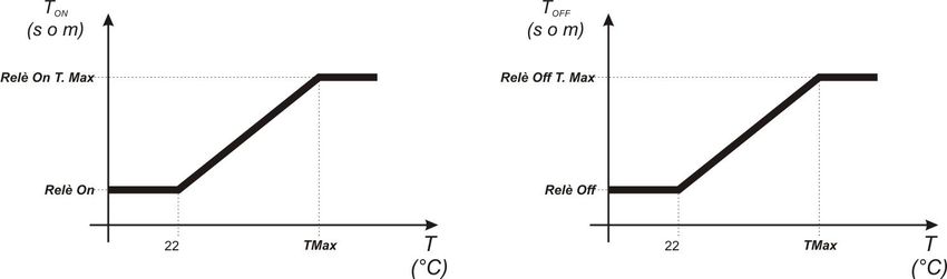
TECHNOPOOL3 INTRODUCTION
Dosing systems for swimming pools ENGLISH
1.2 Conformity
Our pumps are manufactured according to General Standards in force and in compliance with the following
European Directives:
n° 2014/30/CE “ e s.m.i.
n° 2014/35/CE “DBT Low Voltage Directive” e s.m.i.
n° 2011/65/UE , 2012/19/UE “direttive RoHs e WEEE” e s.m.i.
To achieve the best and ensure the longest durability of the system, read and follow the rest of the manual
especially the part relative to maintenance.
The manufacturer declines any responsibility for damages on the system caused by non-qualified
personnel.
1.3 Technical features
Back-lit LCD display 2x16.
Red LED (pH) pH alarm signal.
Red LED (Rx) redox alarm signal.
Main ON/OFF switch.
Dose enable switch for each pump.
Solenoid valve output (dry contact, no voltage).
Flow sensor input.
Due inputs for level probes.
An input for temperature probe PT 100.
A BNC input for pH electrode.
A BNC input for redox electrode.
Alarm repetition output 24VDC.
Hereunder are the maximum pump capacities:
4 L/h @ 1 bar, Santoprene® tube. 1 L/h @ 3 bar, Silicone tub
1.4 Electrical features
Power supply: 100÷240 VAC 50/60 Hz and consumption (max): 14 W.
pH Range: 0.00…14.00.
Redox Range: 0…1000 mV.
Temperatura range (PT100): 0…100° C.
1.5 Packaging content
Technopool pH-Rx System.
Instruction manual.
Wall mounting bracket.
Screws and wall plugs for wall fixing.
pH 4 buffer solution.
pH 7 buffer solution.
475mV buffer solution.
pH electrode with 5 m cable.
Redox electrode with 5 m cable.
3-wire temperature probe PT100 with 5 m cable.
DN50 collars (3 pcs).
Suction filter (2 pcs).
Injection valve (2 pcs).
Probe holder (2 pcs).
Suction and delivery tubes.
ADSP7000716 rev. 1.0 25/01/2017 4/64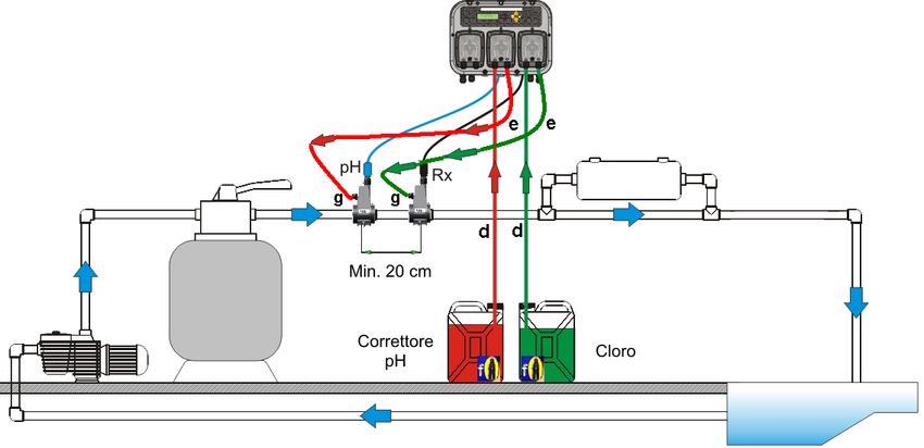
TECHNOPOOL3 INSTALLATION
Dosing systems for swimming pools ENGLISH
2 INSTALLATION
In vertical position with an uncertainty not higher than +/-15°.
Away from heat sources and in a dry place, with room temperature ranging between 0°C and 45°C.
In a ventilated place and easily accessible to an operator for ordinary maintenance.
At maximum 1.5 m high from the liquid to be dosed.
Do not install the system above the chemical tank if it emits smoke, unless the container is not hermetically
closed.
2.1 Wall mounting
Place the system on a wall close to the dosing section and follow the instructions described below.
2.2 Electrical connections
Before proceeding with the installation, ensure the presence of a suitable earthing connection and of an
appropriate sensitive differential switch. Observe electrical values indicated on the system label.
ATTENTION: Before carrying out maintenance on the system, always disconnect the power supply.
Always check all electrical connections, by using a multimeter. An incorrect voltage may damage the
system not covered by the guarantee. The following manual must always be kept as reference for
any electrical connection.
All electrical connections must be carried out in compliance with local laws regarding electrical
systems.
CAUTION !!!!!
Verify that the earth system is perfectly functional and complies with the applicable regulations.
Ensure the unit is connected to a circuit protected by a highly sensitive (0.03A) RCCB circuit
breaker. If unsure please consult a competent electrician. Verify that the rated values of the pump
are compatible with those of the mains. Never install the pump directly in parallel with inductive
loads (e.g. motors/solenoid valves) if necessary, use an isolating relay.
There are 2 protection devices inside the pump: a varistor and a fuse.
2.2.1 Main power supply
Connect a voltage between 100 and 240VCA - 50/60Hz on clamp .
2.2.2 Temperature probe
Connection of the temperature probe PT100 to the corresponding clamp; depending on the probe model available,
carry out one of the connections described below:
2.2.3 Flow signal
Connect the flow sensor signal on input PROX.
ADSP7000716 rev. 1.0 25/01/2017 5/64
TECHNOPOOL3 INSTALLATION
Dosing systems for swimming pools ENGLISH
2.2.4 Dosing enabling signal (V1)
Connect the enablement signal to the dosing (20-230VAC) on input CHARGE.
2.2.5 pH pump product level probe
Connect the level probe (on/off contact, without voltage) to input LEVEL RIN.
2.2.6 Rx pump product level probe
Connect the level probe (on/off contact, without voltage) to input LEVEL SAN.
2.2.7 Alarm output – 24V OUT Clamp
It is an alarm repetition output that provides a voltage at 30VCC with a
maximum absorption of 500mA.
2.2.8 Solenoid valve output – RELAY Clamp
RELAY clamp provides a dry contact (not live) and it is used to control
the solenoid valve.
To have a voltage on the RELAY clamp equal to the power voltage, i.e.
230VAC, follow the diagram indicated on the side.
2.2.9 Pump switches
The system can be set with dose enable switches for each pump, which block the dosing of the associated pump.
Switches are connected to the circuit in the following way:
pH Pump on connector J16
Rx Pump on connector J15
ADSP7000716 rev. 1.0 25/01/2017 6/64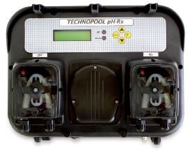
TECHNOPOOL3                                                 INSTALLATION

Dosing systems for swimming pools                               ENGLISH

2.3 Hydraulic connections

ADSP7000716                         rev. 1.0   25/01/2017           7/64

TECHNOPOOL3                                                                                                INSTALLATION

Dosing systems for swimming pools                                                                                 ENGLISH

2.3.1 Assembly of the accessories
Probe holder assembly
- The injection probe holder (j) can be installed on a DN50 or DN60 PVC tube, after a 24mm hole has been
drilled
- Ensure the injection tube is inserted so that it points in the direction of flow marked by the arrow
                                                                o
- The injection probe holder must be installed within ± 45 of the vertical.
How to make D24mm hole
- Drill a 5 mm pilot hole in the top of the PVC tube
- Enlarge the hole with the special tool D24mm supplied in the kit
- Remove any burrs from the hole
2 in 1 Probe holder installation(ref. j):
- Put the o-ring (ref. 8) on the injection tube
- Insert the injection tube inside the PVC tube, ensuring that the injection is in the same direction as the pool
circulation (indicated by the arrow on the sticker)
- Put the big o-ring in its seat keeping it in its position, place the upper part of the probe holder (ref. j) on the
PVC tube
- Use the screws to join the 2 parts of the probe holder (if the PVC pipe is DN63 use the 2 spacer (ref. 9))
Warning Do not fully tighten one nut before the other.

                                                                            Installation of 4 x 6 tube (ref. 2) on d
                                                                            e f g elements

Long probe Installation (120 mm)
- A standard electrode (12x120 mm) can be used, in that case you must use all the
accessories inside the kit
- Put the nut (ref. 11) on the probe body and than, alternatively, one spacer (ref. 6) and one
o-ring (ref. 7), like shown in the picture on the side
- Insert with care the electrode in the probe holder, having care that all the components
reach their seats. Then screw the nut with care (ref. 11).
Warning Do not bend the electrode otherwise it will be damaged. Electrode inner part is
very fragile.

ADSP7000716                            rev. 1.0                         25/01/2017                                      8/64
TECHNOPOOL3 TECHNOPOOL3 MENU Dosing systems for swimming pools ENGLISH 3 Technopool pH-Rx MENU Technopool pH-Rx programming system is divided in 2 menus: User and Installer. ADSP7000716 rev. 1.0 25/01/2017 9/64
TECHNOPOOL3                                                                                               TECHNOPOOL3 MENU

Dosing systems for swimming pools                                                                                         ENGLISH

3.1 User Menu
The User Menu is used to verify the status of pumps and solenoid valve and also allows to prime the pumps.

                                       Default screen shows the reading of the pH, Rx and the temperature.

                                       Shows the status and the alarm of the pumps and solenoid valve.

                                       Displays the status of pH pump.
                                                                      Status                            Description
                                                                 Active             The pump is active
                                                                 Inactive           The pump is inactive
                                                                 Flow alarm         Flow alarm active
                                                                 Circ. Pump Off     The recirculation pump is not operating
                                                                 Switch Off         The pump switch is set on OFF
                                                                 Level alarm        The product tank is empty
                                                                 Range alarm        Reading of pH out of the allowed range
                                                                 OFA alarm          Dosing alarm
                                                                 Stabilisation      Stabilisation of the probe reading
                                       Displays the status of Rx pump.
                                                                      Status                            Description
                                                                 Active             The pump is active
                                                                 Inactive           The pump is inactive
                                                                 Flow alarm         Flow alarm active
                                                                 Circ. Pump Off     The recirculation pump is not operating
                                                                 Switch Off         The pump switch is set on OFF
                                                                 Level alarm        The product tank is empty
                                                                 OFA alarm          Dosing alarm
                                                                 Stabilisation      Stabilisation of the probe reading

                                       Displays the status of the solenoid valve.
                                                                      Status                            Description
                                                                 Active             The solenoid valve is active
                                                                 Inactive           The solenoid valve is inactive
                                                                 Flow alarm         Flow alarm active
                                                                 Circ. Pump Off     The recirculation pump is not operating
                                                                 Stabilisation      Stabilisation of the probe reading

ADSP7000716                         rev. 1.0                               25/01/2017                                         10/64
TECHNOPOOL3 TECHNOPOOL3 MENU
Dosing systems for swimming pools ENGLISH
3.1.1 Manual activation of pumps and solenoid valve
The priming sub-menu can be accessed from the user menu, which allows the manual operation of pumps and
solenoid valve.
To access this menu, press key F for 3 seconds; the following options will be displayed:
pH corrector
Press keys ▼▲ to set manually the values to be dosed and Enter to confirm and
activate the dosing of the pH pump.
The dosing that can be set is 0÷999 ml or 1.0÷9.9 litres.
Rx corrector
Press keys ▼▲ to set manually the values to be dosed and Enter to confirm and
activate the dosing of the Rx pump.
The dosing that can be set is 0÷999 ml or 1.0÷9.9 litres.
Solenoid valve priming
Press keys ▼▲ to set manually the opening schedule of the solenoid valve and
Enter to confirm and activate its opening.
The schedule that can be set is 0÷50 seconds (at steps of 10 seconds) or 1÷60
minutes (at steps of 1 minute).
Temperature (is displayed only if the temperature is not set on OFF)
Press keys ▼▲ to set the required temperature, only if the temperature has been
set manually.
The temperature can be set at 0÷100° C.
Press key F for 3 seconds to exit the priming menu, or exit automatically after a
minute without pressing any key.
ADSP7000716 rev. 1.0 25/01/2017 11/64TECHNOPOOL3 TECHNOPOOL3 MENU
Dosing systems for swimming pools ENGLISH
3.2 Installer menu
The installer menu is used to program Technopool pH-Rx system.
To access this menu, press key Enter for 3 seconds; password request will be displayed:
3.2.1 Password insertion
Press keys ▼▲ to set the value; to pass to the next digit press key Enter; to confirm press
Enter for 3 seconds.
The default password is 0000.
Once the password is confirmed, the installer menu will be displayed.
Language
Set the language of the system.
Date of the latest modif.
Indicates the date of the latest modification carried out by the system.
pH calibration
Activates the procedure for the calibration of the pH electrode.
Rx calibration
Activates the procedure for the calibration of the redox electrode.
Set Point/Timer
Programs the operations of the peristaltic pumps and control relays of the solenoid valve.
Def. Par. Rest.
Restores default parameters.
Settings
Set the system.
Temperature
Set the system temperature management.
Alarms
Management of all the system alarms is configured.
Initial menu
Return to the user menu.
ADSP7000716 rev. 1.0 25/01/2017 12/64TECHNOPOOL3 QUICK PROGRAMMING
Dosing systems for swimming pools ENGLISH
4 quick programming
4.1 Selection of the language of the system
Select option Language from the installer menu.
To confirm and exit, press key Enter for 3 seconds.
4.2 Setting the temperature
Select option Temperature from the installer menu.
Temperat. Mode
Indicates how the temperature is managed: manually, automatically (with probe
PT100) or OFF (deactivated).
Press keys ▼▲ to select the mode and Enter to confirm.
PT100 offset (only if the Temperat. Mode is PT100)
This parameter allows to adjust the temperature display. In fact, the offset value
can be added to or removed from the measured temperature, so to display the
desired value. This parameter is not considered for the calculation of the dosing
but only for the display.
Press keys ▼▲ to set the desired value and Enter to confirm.
Values that can be set are -5.0÷10.0.
Man. Temperat. (only if the Temperat. Mode is Manual)
It represents the coefficient for calculating the compensation of conductivity; it is
recommended to leave the default value.
Press keys ▼▲ to set the desired value and Enter to confirm.
Values that can be set are 0÷100° C.
To confirm and exit, press key Enter for 3 seconds.
ADSP7000716 rev. 1.0 25/01/2017 13/64TECHNOPOOL3 QUICK PROGRAMMING
Dosing systems for swimming pools ENGLISH
4.3 Setting the pH (pump pH)
The following parameters must be programmed for pH pump operation:
Set Point pH – Work Mode pH – Prop. Band pH
Enter the installer menu, select option Set Point/Timer , press key Enter and then key F more than once, until Set
Point pH is displayed:
Set Point pH
The setpoint indicates the value of pH that is intended to keep.
Press keys ▼▲ to set the desired setpoint and Enter to confirm.
Setpoint values that can be set are 5.0÷9.0 pH.
Work mode pH
The operation mode sets the type of solution it is being dosed: Acid (the pump
starts dosing when the value read by the probe is higher than the Setpoint) or
Alkaline (the pump starts dosing when the value read by the probe is lower than
the Setpoint).
Press keys ▼▲ to select the two options and Enter to confirm.
- +
pH Work mode that can be set is Acid/pH or Alkaline/pH .
Proportional band pH
Represents the value of the band for the proportional dosing in time.
The pump can be active for maximum 300 seconds. If it is activated for less
time, it must be inactive for a time equal to the difference between the set pH
cycle period (refer to par. 5.1) and the activation time.
Press keys ▼▲ to set the desired value and Enter to confirm.
The proportional band can be selected among the following values:
0.5 – 1 – 1.5 – 3 pH.
Time TON of pump activation is calculated with the following formula:
Read value - Set point difference is considered an absolute value.
On the other hand, TOFF is the difference between the set pH cycle period – TON.
Example:
Set Point pH = 7 pH
-
Work Mode pH = Acid/pH
Prop. band pH = 1.5 pH
Read value pH = 7.5 pH
If during the dosing the pump reaches the setpoint, then it stops for the time obtained by the difference
between the set pH cycle period (refer to par. 5.1) and the time the pump was active.
ADSP7000716 rev. 1.0 25/01/2017 14/64TECHNOPOOL3 QUICK PROGRAMMING
Dosing systems for swimming pools ENGLISH
4.4 Setting the redox (P2 pump)
P2 Pump doses proportionally to the setpoint reading.
The following parameters must be programmed for redox pump operation:
Set Point Rx – Prop. band Rx
Enter the installer menu, select option Set Point/Timer , press key Enter and then key F more than once, until Set
Point Rx is displayed:
Set Point Rx
The setpoint indicates the value of Rx that is intended to keep.
Press keys ▼▲ to set the desired setpoint and Enter to confirm.
Setpoint values that can be set are 0÷1000 mV.
Proportional band Rx
Represents the value of the band for the proportional dosing in time.
The pump can be active for maximum 300 seconds. If it is activated for less
time, it must be inactive for a time equal to the difference between 300 and the
activation time.
Press keys ▼▲ to set the desired value and Enter to confirm.
The proportional band can be selected among the following values:
20 – 50 – 100 – 200 mV.
Time TON of pump activation is calculated with the following formula:
Read value - Set point difference is considered an absolute value.
On the other hand, TOFF is the difference between 300 – TON.
Example:
Set Point Rx= 700 mV
Prop. band Rx = 50 mV
Read value Rx = 675 mV
If during the dosing the pump reaches the setpoint, then it stops for the time obtained by the difference
between 300 seconds and the time the pump was active.
ADSP7000716 rev. 1.0 25/01/2017 15/64TECHNOPOOL3 QUICK PROGRAMMING
Dosing systems for swimming pools ENGLISH
4.5 Setting the solenoid valve
The operation mode of the control relay of the solenoid valve can be ON/OFF or cyclical.
ON/OFF: The relay opening and closing is controlled by the redox reading; if the system reads a value lower
than the set Setpoint, then the relay is activated (ON), otherwise it is deactivated (OFF). In this case, a
hysteresis of 10 mV (redox, Rx) must be considered.
Cyclical: The relay opening and closing is continuously controlled by the On and OFF timing, which can be
proportional to the temperature (set on automatic or manual) or not (temperature set on OFF).
Manual temperature or with PT100:
Relay On – Relay On T. Max – Relay Off – Relay Off T. Max
Temperature OFF (disabled):
Relay On – Relay Off
Enter the installer menu, select option Set Point/Timer , press key Enter and then key F more than once,
until Relay On is displayed:
Temperature OFF (disabled):
Relay On
It indicates the relay ON schedule (solenoid valve open).
Press keys ▼▲ to set the desired value and Enter to confirm.
Values that can be set are 0÷59 seconds or 1÷60 minutes.
Relay Off
It indicates the relay OFF schedule (closed solenoid valve).
Press keys ▼▲ to set the desired value and Enter to confirm.
Values that can be set are 0÷59 seconds or 1÷60 minutes.
ADSP7000716 rev. 1.0 25/01/2017 16/64TECHNOPOOL3 QUICK PROGRAMMING
Dosing systems for swimming pools ENGLISH
Manual temperature or with PT100:
Relay On
It indicates the relay ON schedule (solenoid valve open).
Press keys ▼▲ to set the desired value and Enter to confirm.
Values that can be set are 0÷59 seconds or 1÷60 minutes.
Relay On T. Max
Indicates the ON timing of the relay (solenoid valve open) to the
programmed maximum temperature value.
Press keys ▼▲ to set the desired value and Enter to confirm.
Values that can be set for the timing are 0÷59 seconds or 1÷60 minutes;
whereas 23÷36° C for the temperature.
Relay Off
It indicates the relay OFF schedule (closed solenoid valve).
Press keys ▼▲ to set the desired value and Enter to confirm.
Values that can be set are 0÷59 seconds or 1÷60 minutes.
Relay Off T. Max
Indicates the OFF timing of the relay (solenoid valve closed) to the
programmed maximum temperature value.
Press keys ▼▲ to set the desired value and Enter to confirm.
Values that can be set for the timing are 0÷59 seconds or 1÷60 minutes;
whereas 23÷36° C for the temperature.
The two ON and OFF timings are proportional to the temperature reached during the latest dosing, according
to the diagram below:
To calculate exactly the dosing, the following formulas can be applied:
ADSP7000716 rev. 1.0 25/01/2017 17/64TECHNOPOOL3 QUICK PROGRAMMING
Dosing systems for swimming pools ENGLISH
4.6 Calibration of pH electrode
The calibration of the pH electrode is carried out on two points, therefore it is requested to have the following
material always available:
pH 7 buffer solution.
pH 4,01 buffer solution.
Container with water for cleaning the electrode (i.e. a glass).
Select the option pH Calibration from the installer menu and follow the instructions displayed.
Once carried out the pH 7 calibration, rinse the electrode with water, so to prevent the pH 4 solution
from polluting.
Once the procedure is completed, the quality of the calibrated electrode will be displayed; if the quality of the
probe results 25% or less, carry out a new calibration.
Should the result still be 25% or less, it is recommended to replace the probe.
4.7 Calibrating the redox electrode
The calibration of the redox electrode is carried out only on one point, therefore it is requested to have the
following material always available:
475 mV buffer solution.
Select the option Rx Calibration from the user menu and follow the instructions displayed.
Once the procedure is completed, the quality of the calibrated electrode will be displayed; if the quality of the
probe results 25% or less, carry out a new calibration.
Should the result still be 25% or less, it is recommended to replace the probe.
ADSP7000716 rev. 1.0 25/01/2017 18/64TECHNOPOOL3 GUARANTEE CERTIFICATE
Dosing systems for swimming pools ENGLISH
5 ADVANCED PROGRAMMING
5.1 Configuration of the settings
Stabiliz. Time
When the system is powered or after an alarm occurred, it waits a
stabilisation time before it starts dosing (probes need some minutes to
stabilise the readings).
Stab. after alarm
Enables or disables the stabilisation time, after every alarm of the system.
Time and Date
Sets hour and date of the system
Press keys ▼▲ to set the value and Enter to move the slider.
Password setting
Set the password of the system.
Press keys ▼▲ to set the value and Enter to move the slider.
User name
Set the name of the client.
Press keys ▼▲ to select a character and Enter to move the slider.
Contact assist.
Set the name and telephone number of the After-Sales Assistance.
Press keys ▼▲ to select a character and Enter to move the slider.
pH Cycle period
It is the time that must pass between the two doses for the pH pump.
Press keys ▼▲ to set the desired value and Enter to confirm.
Values that can be set for the timing are 5÷120 minutes.
Contrast
This is the contrast percentage of the LCD.
Use the ▼▲ keys to set the desired value and then confirm with the Enter
key. The time values that can be set are 1÷100.
To confirm and exit, press key Enter for 3 seconds.
5.2 Restore the default parameters
The restoration of the factory parameters is enabled (refer to appendix 1). The
system asks if you are sure to proceed.
Press keys ▼▲ to select the two options and Enter to confirm.
By activating this function, all programmed data will get lost!
ADSP7000716 rev. 1.0 25/01/2017 19/64TECHNOPOOL3 GUARANTEE CERTIFICATE
Dosing systems for swimming pools ENGLISH
6 Alarms
The system is equipped with the following alarms:
Level alarm, with 3 seconds of hysteresis; this alarm interrupts the operation of the relative pump.
Flow alarm, with 3 seconds of hysteresis; this alarm interrupts the dosing of the system.
Dosing enabling alarm, with 3 seconds of hysteresis; this alarm interrupts the dosing of the system.
pH measure alarm: The system is equipped with a pH reading alarm. If the value of the pH is lower than 5
and higher than 9, the system stops the pumps. If the value of pH is lower than 5 or higher than 9, it is
recommended to control the probe and the quality of the water.
Dosing Alarm: product dose with no effect (with no variation in the pH or Rx reading). The dosing alarms
can only be removed by restarting the system (use the ON/OFF switch) or automatically, when the
measure nears the setpoint.
6.1 Setting the alarms
Select Alarms in the installer menu.
Contr. Dos. (V1). Enables or disables the dosing, when signal V1 occurs
(signal of the active recirculation pump).
Press keys ▼▲ to select the two options and Enter to confirm.
Flow control. Enables or disables the dosing, when water flow occurs.
Press keys ▼▲ to select the two options and Enter to confirm.
pH dosing alarm. This is a dosing alarm and if the pH pump doses the
product and there is no variation in pH (0.05 pH) during the set time, the
system signals the alarm and stops dosing.
The alarm is automatically disabled when the setpoint is neared (when the
difference between the pH measure and the setpoint is less than 0.2 pH).
Use the ▼▲ keys to set the desired value or disable the alarm (Off) and
then confirm with the Enter key.
The time values that can be set are 5÷60 minutes.
Rx dosing alarm. This is a dosing alarm and if the Rx pump doses the
product and there is no variation in Rx (5 mV) during the set time, the
system signals the alarm and stops dosing.
The alarm is automatically disabled when the setpoint is neared (when the
difference between the pH measure and the setpoint is less than 20 mV).
Use the ▼▲ keys to set the desired value or disable the alarm (Off) and
then confirm with the Enter key.
The time values that can be set are 5÷60 minutes.
Buzzer. Activates or deactivates the alarm acoustic signal.
Press keys ▼▲ to select the two options and Enter to confirm.
Out 24V Alarm. Sets the operation mode of Out 24V output, which can be
set either open or closed, when alarms occur.
Press keys ▼▲ to select the two options and Enter to confirm.
6.2 Alarm signal
Alarms are always signalled by the LCD display with the wording Alr.
Moreover, the two LEDs light on to indicate that the pH or redox pump has an alarm situation in progress.
ADSP7000716 rev. 1.0 25/01/2017 20/64TECHNOPOOL3 GUARANTEE CERTIFICATE
Dosing systems for swimming pools ENGLISH
7 Winter pause
It is recommended to work the system with tap water to clean the tube and avoid chemical attacks during the pause
period. Probes must be removed from the installation, during the winter pause. The protective cap must be filled
with 1/3 of water and placed on the probe edge.
8 Operations to carry out at the beginning of the season
It is recommended to install a new probe at the beginning of the season, to prevent the system from
malfunctions.
Once replaced the electrode or when restarting the system, repeat the calibration procedure.
9 Return to the after-sales service
The material must be sent back in its packaging with all its original protection devices before the guarantee period
is completed.
The system must be clean and the chemical product removed from the tubes.
The measure electrode must be placed in its original packaging and protected with the cap full of water.
The manufacturer declines any responsibility regarding damages caused by transportation, if the aforementioned
conditions are not respected.
10 Guarantee certificate
The manufacturer guarantees the material for a period of 24 months from the date of delivery to the first buyer.
During this period of time, after an examination of the manufacturer or an authorised reseller, the manufacturer will
provide free of charge any failed component which material or processing is found defective or, at its option, the
component will be repaired directly or through authorised workshops.
All components subjected to normal wear are excluded from the guarantee, such as: tubes, valves, gaskets,
connections, tube ring-nuts, filters, injection valves, probes, electrodes and glass components.
The manufacturer declines any responsibility and obligation regarding other costs, damages and direct or indirect
losses arising from the use or inability to use the pump, in whole or in part.
Repair and replacement shall not extend or renew the guarantee period. Assembly and dismantling costs of the
system pumps, transportation costs and used materials (filters, valves, etc.) are borne by the buyer.
The right to repair or replace under guarantee becomes void when:
The pump is not used according to installation, use and maintenance instructions provided by the
manufacturer.
The pump is repaired, dismantled or modified by non-authorised workshops.
Non-original spare parts or accessories have been used.
The injection system is damaged after using incompatible products.
The electric system is damaged for external causes of any type, for example overvoltages.
At the end of the 24th month from the date of delivery, the manufacturer will be released from all the above
mentioned obligations.
Pursuant to directives 2011/65/UE , 2002/96/EC, 2003/108/EC), it is notified that:
The electric and electronic devices must not be considered as household waste.
Consumers are obliged by law to return electrical and electronic devices at the end of their service lives to the public collecting
points set up for the purpose or point of sale, when purchasing a new equivalent device in terms of one-to-one. The crossed out
rubbish mean symbol on the product, on the instructions manual or on the packaging indicates that the product is subject to the
disposal rules envisioned by the Standard. Illegal disposal of the product implies the application of the administrative fines
provided for by national regulations. By recycling, reusing the material or other forms of utilising old devices, you are making an
important contribution to protecting our environment.
ADSP7000716 rev. 1.0 25/01/2017 21/64TECHNOPOOL3 APPENDIX 2
Dosing systems for swimming pools ENGLISH
11 APPENDIX 1 – Default parameters
Parameter Default value
Language English
Set Point pH 7,4
pH Work Mode Acid
Proportional Band pH 1
Set Point Rx 650 mV
Proportional Band Rx 50 mV
Relay Mode Cyclical
Relay On 0s
Relay On at the maximum temperature 0s
Relay Off 0s
Relay Off at the maximum temperature 0s
Maximum Temperature for Relay Timing 28 ˚C
Stabilisation Time 30 s
Stabilisation after Alarm No
Password “0000”
User name “ “
Contact assist. “ +390522695805 “
Out 24V Alarm (alarm repetition) Closed with Alarm
Temperature Mode PT100
Manual Temperature 25 ˚C
Offset PT100 0 ˚C
Dosing Control (V1) On
Flow Control Off
pH dosing Alarm Off
Rx dosing Alarm Off
Buzzer (alarm repetition) Off
System kind Technopool TpH
Pump pH flow 1.4 l/h
Pump Rx flow 1.4 l/h
Pump pH Max flow 4.0 l/h
Pump Rx Max flow 4.0 l/h
pH Cycle Period 5 min
Contrast 25
ADSP7000716 rev. 1.0 25/01/2017 22/64TECHNOPOOL3 INHALTSVERZEICHNIS
Dosieranlage für Schwimmbecken DEUTSCH
INHALTSVERZEICHNIS
1 EINFÜHRUNG .................................................................................................................................................. 24
1.1 Warnhinweise ............................................................................................................................................. 24
1.2 Übereinstimmung ....................................................................................................................................... 25
1.3 Technische Eigenschaften ......................................................................................................................... 25
1.4 Elektrische Eigenschaften .......................................................................................................................... 25
1.5 Verpackungsinhalt...................................................................................................................................... 25
2 INSTALLATION ................................................................................................................................................ 26
2.1 Wandbefestigung ....................................................................................................................................... 26
2.2 Elektrische Anschlüsse .............................................................................................................................. 26
2.2.1 Hauptstromversorgung ........................................................................................................................ 26
2.2.2 Temperatursonde ................................................................................................................................ 26
2.2.3 Durchflusssignal .................................................................................................................................. 26
2.2.4 Freigabesignal der Dosierung (V1) ..................................................................................................... 27
2.2.5 pH-Pumpe-Produktfüllstandsonde ...................................................................................................... 27
2.2.6 Rx-Pumpe-Produktfüllstandsonde....................................................................................................... 27
2.2.7 Alarmausgang – Klemme OUT 24V .................................................................................................... 27
2.2.8 Magnetventilausgang – Klemme RELAY ............................................................................................ 27
2.2.9 Pumpenschalter .................................................................................................................................. 27
2.3 Hydraulische Anschlüsse ........................................................................................................................... 28
2.3.1 Montage der Zubehörteile ................................................................................................................... 29
3 MENÜ Technopool pH-Rx ................................................................................................................................ 30
3.1 Menü Benutzer ........................................................................................................................................... 31
3.1.1 Manuelle Aktivierung der Pumpen und des Magnetventils ................................................................. 32
3.2 Menü Installateur........................................................................................................................................ 33
3.2.1 Passworteingabe ................................................................................................................................. 33
4 Schnellprogrammierung.................................................................................................................................... 34
4.1 Auswahl der Systemsprache ..................................................................................................................... 34
4.2 Einstellung der Temperatur ........................................................................................................................ 34
4.3 pH-Einstellung (pH-Pumpe) ....................................................................................................................... 35
4.4 Redox-Einstellung (P2-Pumpe) ................................................................................................................. 36
4.5 Einstellung des Magnetventils ................................................................................................................... 37
4.6 Kalibrierung der pH-Elektrode .................................................................................................................... 39
4.7 Kalibrierung der Redox-Elektrode .............................................................................................................. 39
5 FORTGESCHRITTENE PROGRAMMIERUNG ............................................................................................... 40
5.1 Konfiguration der Einstellungen ................................................................................................................. 40
5.2 Wiederherstellung der Default-Parameter ................................................................................................. 40
6 Alarme............................................................................................................................................................... 41
6.1 Einstellung der Alarme ............................................................................................................................... 41
6.2 Anzeige der Alarme.................................................................................................................................... 41
7 Winterpause ...................................................................................................................................................... 42
8 Durchzuführende Arbeiten zu Saisonbeginn .................................................................................................... 42
9 Rücksendung an den Kundendienst ................................................................................................................. 42
10 Garantieschein ................................................................................................................................................ 42
11 ANHANG 1 - Default-Parameter..................................................................................................................... 43
ADSP7000716 rev. 1.0 25/01/2017 23/64TECHNOPOOL3 EINFÜHRUNG
Dosieranlage für Schwimmbecken DEUTSCH
1 EINFÜHRUNG
Das Technopool pH-Rx ist ein integriertes System, das in der Lage ist, zwei Peristaltikpumpen und ein
Magnetventil-Steuerrelais für die automatische Verwaltung der Wasseraufbereitung im Schwimmbecken zu
steuern.
Für die Produktpalette der Familie Technopool pH-Rx ist Bezug auf den Anhang 2 zu nehmen.
Das Technopool pH-Rx kann zwei Peristaltikpumpen verwalten, die auf die folgenden Arten gesteuert werden:
pH-Pumpe: Für die Dosierung des pH-Korrektors.
Es wird der im Schwimmbecken aufrecht zu erhaltende Sollwert des pH-Wertes eingestellt.
Rx-Pumpe: Für die Dosierung des Desinfektionsmittels.
Es wird der im Schwimmbecken aufrecht zu erhaltende Sollwert des Redox-Wertes eingestellt.
Andererseits kann das Magnetventil-Steuerrelais für die Dosierung der Chortabletten auf zwei Arten programmiert
werden:
zyklisch
Die Öffnungszeiten (ON) und Schließzeiten (OFF) des Relais sind festgelegt oder proportional zur
Wassertemperatur, die bei der letzten Dosierung erreicht wurde.
ON/OFF
Die Öffnungszeiten (ON) und die Schließzeiten (OFF) werden von der Redox-Sonde gesteuert; daher
hängt es von der Sollwert-Einstellung mit einer festen Hysterese von 10 mV (Redox) ab.
1.1 Warnhinweise
Diese Anleitung soll alle notwendigen Informationen für eine ordnungsgemäße Installation und Wartung des
Systems liefern, um Ihnen die besten Ergebnisse während des Betriebs zu bieten.
Aus diesem Grund ist es sehr wichtig, die nachstehend aufgeführten Anweisungen aufmerksam zu lesen. Es
werden alle notwendigen Hinweise für die Sicherheit der Installation, des Gebrauchs und der Wartung geliefert.
Diese Anleitung sorgfältig aufbewahren, damit sie bei Bedarf konsultiert werden kann.
Die Integrität des Systems bei der Auslieferung aufmerksam kontrollieren. Bei Anomalien, vor der
Durchführung jeglicher Eingriffe, Fachpersonal zu Rate ziehen.
Vor der Installation sicherstellen, dass die Daten des Typenschilds des Systems den Spezifikationen der
elektrischen Anlage entsprechen.
Nicht mit nackten Füßen und/oder Händen arbeiten.
Das System keinen Witterungseinflüssen aussetzen.
Die Eingriffe am System müssen von Fachpersonal durchgeführt werden.
Bei anormalem Betrieb sofort das System ausschalten und den Kundendienst für die erforderlichen
Reparaturen kontaktieren.
Für einen korrekten Betrieb müssen Original-Zubehörteile und -Ersatzteile verwendet werden.
Der Hersteller übernimmt keine Haftung für Schäden aufgrund eines unsachgemäßen Einsatzes oder der
Verwendung von Nicht-Original-Zubehörteilen oder -Ersatzteilen.
Die elektrische Anlage muss den geltenden Richtlinien des Landes entsprechen, in dem sie erstellt wird.
Die Temperatur des Raumes, in dem das System installiert wird, darf 45 °C nicht überschreiten.
ADSP7000716 rev. 1.0 25/01/2017 24/64TECHNOPOOL3 EINFÜHRUNG
Dosieranlage für Schwimmbecken DEUTSCH
1.2 Übereinstimmung
Unsere Pumpen werden gemäß den allgemein geltenden Normen und in Übereinstimmung mit den folgenden
Europäischen Richtlinien hergestellt:
Nr. 2014/30/EG und spätere Änderungen und Ergänzungen
Nr. 2014/35/EG „NSR Niederspannungsrichtlinie“ und spätere Änderungen und Ergänzungen
Nr. 2011/65/EU, 2012/19/EU „Richtlinien RoHs und WEEE“ und spätere Änderungen und Ergänzungen
Für die besten Ergebnisse und die Gewährleistung der maximalen Funktionstüchtigkeit des Systems, den Rest des
Handbuchs aufmerksam lesen und befolgen, insbesondere den Teil bezüglich der Wartung.
Der Hersteller übernimmt keine Haftung für Schäden am System, die durch nicht-qualifiziertes
Personal verursacht werden.
1.3 Technische Eigenschaften
Alphanumerisches LCD-Display 2x16 mit Hintergrundbeleuchtung.
Rote LED (pH) pH-Alarmanzeige.
Rote LED (Rx) Redox-Alarmanzeige.
Hauptschalter ON/OFF.
Freigabeschalter der Dosierung für jede Pumpe.
Magnetventilausgang (Trockenkontakt, keine Spannung).
Eingang des Durchflusssensors.
Zwei Eingänge für Füllstandsonden.
Ein Eingang für Temperatursonde PT100.
Ein BNC-Eingang für pH-Elektrode.
Ein BNC-Eingang für Redox-Elektrode.
Alarm-Wiederholungsausgang 30VCC.
Die maximal verfügbaren Pumpenleistungen sind folgende:
4 L/h @ 1 bar, Rohr aus Santoprene®. 1 L/h @ 3 bar, Rohr aus Silikon.
1.4 Elektrische Eigenschaften
Stromversorgung: 100÷240 VCA 50/60 Hz. mit Verbrauch (max.): 14 W.
pH-Bereich: 0,00…14,00.
Redox-Bereich: 0…1000 mV.
Temperaturbereich (PT100): 0…100° C.
1.5 Verpackungsinhalt
System Technopool pH-Rx.
Bedienungsanleitung.
Wandhalterung.
Schrauben und Dübel für die Wandbefestigung.
pH-4-Pufferlösung.
pH-7-Pufferlösung.
475mV-Pufferlösung.
pH-Elektrode mit 5 m Kabel.
Redox-Elektrode mit 5 m Kabel.
Dreiadrige PT100-Temperatursonde mit 5 m Kabel.
Bundstücke DN50 (3 Stück).
Ansaugfilter (2 Stück).
Einspritzventil (2 Stück).
Sondenhalter (2 Stück).
Saug- und Druckleitungen.
ADSP7000716 rev. 1.0 25/01/2017 25/64TECHNOPOOL3 INSTALLATION
Dosieranlage für Schwimmbecken DEUTSCH
2 INSTALLATION
In vertikaler Position mit einer Unsicherheit von nicht mehr als +/-15°.
Weit entfernt von Wärmequellen und an einem trockenen Ort mit einer Umgebungstemperatur zwischen
0 °C und 45 °C.
In einem belüfteten und für den Bediener zur regelmäßigen Wartung leicht zugänglichem Raum.
Bei einer maximalen Höhe von 1,5 m vom Niveau der zu dosierenden Flüssigkeit.
Das System nicht über dem Tank des chemischen Produkts installieren, wenn dieser Rauch abgibt, es sei
denn, der Behälter ist hermetisch verschlossen.
2.1 Wandbefestigung
Das System an einer Wand in der Nähe des Dosierpunkts positionieren und die nachstehend aufgeführten
Anweisungen befolgen.
2.2 Elektrische Anschlüsse
Vor der Installation sicherstellen, dass eine entsprechende Erdung und ein Differentialschalter einer
ordnungsgemäßen Empfindlichkeit vorhanden sind. Die elektrischen Werte beachten, die auf dem Etikett des
Systems angegeben sind.
ACHTUNG: Vor der Durchführung von Wartungseingriffen am System, stets die Stromversorgung
trennen.
Mit einem Multimeter stets alle elektrischen Anschlüsse überprüfen. Eine falsche Spannung könnte
einen Schaden am System verursachen, der nicht durch die Garantie abgedeckt wird. Die
folgende Anleitung ist stets als Referenz für jeden elektrischen Anschluss aufzubewahren.
Alle elektrischen Anschlüsse müssen in Übereinstimmung mit den lokalen Gesetzen für elektrische
Anlagen vorgenommen werden.
ACHTUNG!!!!!
Überprüfen, dass das Erdungssystem einwandfrei funktioniert und den geltenden Richtlinien
entspricht. Sicherstellen, dass ein Differentialschalter von hoher Empfindlichkeit (0,03 A) vorhanden
ist. Überprüfen, dass die Typenschildwerte der Pumpe mit denen des Stromnetzes kompatibel sind.
Die Pumpe niemals direkt parallel zu den induktiven Lasten (z.B.: Motoren/Magnetventile)
installieren, sondern gegebenenfalls ein „Trennrelais“ verwenden. In der Pumpe gibt es zwei
Schutzvorrichtungen: einen Varistor und eine Sicherung
2.2.1 Hauptstromversorgung
An der Klemme eine Spannung zwischen 100 und 240 VAC – 50/60 Hz anschließen.
2.2.2 Temperatursonde
Anschluss der Temperatursonde PT100 an die entsprechende Klemme. Je nach verfügbarem Sondenmodell,
einen der nachfolgend aufgeführten Anschlüsse vornehmen:
Zweiadrige Dreiadrige Vieradrige
Sonde Pt100 Sonde Pt100 Sonde Pt100
2.2.3 Durchflusssignal
Das Signal des Durchflusssensors am Eingang PROX anschließen.
ADSP7000716 rev. 1.0 25/01/2017 26/64TECHNOPOOL3 INSTALLATION
Dosieranlage für Schwimmbecken DEUTSCH
2.2.4 Freigabesignal der Dosierung (V1)
Das Freigabesignal für die Dosierung (20÷240 VAC) am Eingang CHARGE anschließen.
2.2.5 pH-Pumpe-Produktfüllstandsonde
Die Füllstandsonde (Ein-/Aus-Kontakt, spannungsfrei) am Eingang LEVEL RIN anschließen.
2.2.6 Rx-Pumpe-Produktfüllstandsonde
Die Füllstandsonde (Ein-/Aus-Kontakt, spannungsfrei) am Eingang LEVEL SAN anschließen.
2.2.7 Alarmausgang – Klemme OUT 24V
Ist ein Alarm-Wiederholungsausgang, der eine Spannung bei 30 VCC mit
einem maximalen Verbrauch von 500 mA liefert.
2.2.8 Magnetventilausgang – Klemme RELAY
Die Klemme RELAY bietet einen Trockenkontakt (nicht unter Spannung)
und wird zur Steuerung des Magnetventils verwendet.
Phase
Mittelleiter
Um eine Spannung an der Klemme RELAY zu erhalten, die der
Erdung
Versorgungsspannung entspricht, z.B. 240 VAC, das seitlich aufgeführte
Schema befolgen.
2.2.9 Pumpenschalter
Das System kann mit Freigabeschaltern der Dosierung für jede Pumpe ausgestattet werden, welche die Dosierung
der zugehörigen Pumpe blockieren.
Die Schalter sind wie folgt an den Stromkreis angeschlossen:
pH-Pumpe am Verbinder J16
Rx-Pumpe am Verbinder J15
ADSP7000716 rev. 1.0 25/01/2017 27/64You can also read