Navitron Solar Heating System - DIY Installation Review
←
→
Page content transcription
If your browser does not render page correctly, please read the page content below
Navitron Solar Heating System – DIY Installation Review

Introduction
In December 2005, ever rising gas prices, plus the availability of plentiful sunlight for several
months of the year, prompted consideration of a solar panel installation to supplement domestic
water heating from the gas boiler.
Several options were considered during extensive Internet research with much downloading and
printing of data sheets, documentation and .pdf files. Flat panels initially seemed to have cost
advantages, but the evacuated glass tube systems are by far the most effective, even generating
useful energy in winter on cloudy days. However evacuated tubes systems are expensive circa
£3,000+ making financial recovery (break-even) time dubiously long – that is until I discovered
the Navitron system.
Navitron specialise in energy saving, eco-friendly, alternative energy solutions; including
evacuated tube solar systems and wind turbines. The Navitron solar panel is based on the Apricus
system. The main difference of the Navitron system is that it is a fraction of the cost of competitor
systems despite the fact that Navitron went to great expense to achieve approval for the
government Clear-Skies initiative. The Clear-Skies grant only allows a £400 rebate on a
professionally installed system – but you would also qualify for a VAT rate reduction to 5% on the
installation. To qualify, you would have to buy a system that would cost over £4,000 to have
installed - simply to save £400! The Navitron system works just as well with or without approval!
 Author’s update: As with many government ideas, the Clear-Skies initiative ended on 31/03/06,
 being replaced by another DTI gimmick now known as the “Low Carbon Building
 Programme”. Indications are that this is even more difficult to qualify for, since it is necessary
 to comply with many other energy-saving measures before acceptance for the LCBP grant.
The Navitron system cost me a total of £1,500 for DIY installation - and that included updating my
heating system to meet Part L of the new Building Regulations specification. I chose to carry out
this update at the same time as it made practical and financial sense. The standard solar system
with associated pipework and ancillaries was under £1,200.
As an Electrical and Electronics Engineer by profession, I have had many years experience in
electrical installation as well as plumbing and property renovation. Therefore modifying the
original cylinder installation (that I had previously installed some 13 years ago) and installing the
solar panel would be relatively straightforward.
This review describes the installation of a complete Navitron Solar System together with the
modifications necessary to optimise the system. There are numerous hints and tips to ease
installation along with detailed explanations of areas not covered in the Navitron guides.

Sourcing Components
Before purchasing any components, I checked with my local Council Planning Department as to
whether Planning Permission was necessary. As of April 2008, Planning Policy has been relaxed
and providing you have a conventional property in a non-restricted area, it is now possible to
install solar panels under Permitted Development without needing to contact the Local Planning
Office. However in certain cases, especially those living in a Conservation Area, or owning a
Listed Building, it is essential to confirm the situation with your local council, in writing, before
commencing work, as Councils have different policies and attitudes towards energy conservation
systems. If in doubt ask first!
Navitron supplied the 20-tube solar panel kit, 1200mm x 450mm solar cylinder and Resol DeltaSol
BS/3 controller kit. I also purchased the fourth temperature sensor, non-return valve and Armaflex
HT High Temperature pipe insulation for the flow pipe.

                                                 1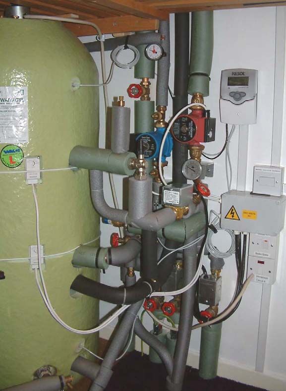
Whilst I used the cheaper Climaflex insulation for the return pipe, the flow pipe can exceed 120ºC
and Climaflex will begin to melt above 105ºC. Therefore the Armaflex HT insulation is essential
for the flow pipe. Some budget insulation materials may melt at temperatures below that of
Climaflex and should be checked before use. For total piece of mind it is generally recommended
to use Armaflex for both flow and return as this ensures that the insulation will not melt under
stagnation conditions.
The only other major components required are the expansion vessel, safety valve and filling loop.
Navitron also sell these as a complete all-in-one kit. However, due to a problem with external wall
(drainage) access from my internal airing cupboard, it was necessary for these items to be
separated within my installation – see later. Hence for this reason I purchased these components
separately.
Various sources were compared on price for copper pipe, fittings and other control equipment. In
fact I used eBay to obtain the Honeywell motorised valves and cylinder thermostats, brand new, at
half price including postage. I was also lucky to win two Horne H-2003 Thermostatic Mixing
Valves (TMVs), normally retailing at £150, for around £45 each. These are high flow rate, low
temperature differential TMVs to BSEN1287 DN20 for bath fill applications and are top quality if
you can pick them up at sensible prices like this. (Note: Horne have subsequently superseded these
with the HeatstatT2 model).
The bulk/trade fittings packs from Screwfix Direct are good value and whilst I buy a lot of these,
you need to do enough plumbing to get full value from them. However is worth noting that a bulk
pack of fittings (or screws etc) from Screwfix often costs less than a small retail blister pack of
similar items from the likes of B&Q. Even if you don’t use them all at once, it is often still cheaper
to buy from Screwfix. Unfortunately there is a vast range of plumbing fittings that are actually
available and on a job like this there are several areas requiring various threaded adaptors, and in
my case 28mm valve and pipe fittings, that Screwfix simply do not sell.
Therefore I sourced some of the remaining parts from Plumbworld and the rest via BES Ltd. – all
online via the Internet.

Installation Planning
In essence, I planned to allow one day each to:
a) Drain down and replace the cylinder, fit new isolating valves, and to fit Thermostatic Mixing
    Valves (TMVs) to the two hot feeds from the cylinder – see note below.
b) Modify the boiler pipework to include three separate new two-port motorised valves in place
    of the existing single three-port valve, fit an Automatic Differential Pressure Bypass Valve
    (ADPBV), as required by Part-L of the new Building Regulations.
c) Carry out the electrical wiring for the new system components.
d) Fit the solar manifold on the roof.
e) Finish solar pipework, test, fit solar tubes, and commission the solar system.
Whilst somewhat over-cautious time wise, the job was planned for late March 2006, when the
weather could still be cold. Apart from (c), the heating system could remain operational due to
isolating valves already fitted to pipes feeding the cylinder coil. Also, the immersion heater in the
new cylinder would provide hot water whilst the boiler pipes were disconnected.
After stage (b), the system would still run in a ‘manual’ mode by locking the manual levers on the
zone valves and allowing the original three-port valve (still electrically connected) to control the
pump and boiler. Whilst not ideal, it was only a one-day temporary fix.
Such cautious planning would not be necessary in the summer months when the family do not
require the heating system to be operational! Also from past experience, it is better to allow for
unforeseeable problems.

                                                  2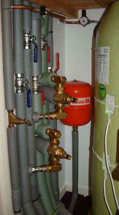
Note: Important safety advice. The solar system is easily capable of heating the cylinder to 65ºC
and water at this temperature will cause instantaneous scalding. This is particularly serious with
children or the elderly. A TMV is used to automatically mix cold water with the hot cylinder flow
to reduce the delivered hot water temperature to a safe level. Because water flow rates from TMVs
are often lower than that from a direct pipe, multiple TMVs may sometimes be necessary, installed
near each point of use.
My domestic system has two 22mm feeds from the cylinder – one to the bathroom, the other
feeding the kitchen, utility room and cloakroom. Hence in my case, two high flow rate TMVs were
utilised.

Solar Cylinder Selection
Assuming the existing cylinder is correctly sized for the needs of the property and occupants, the
solar cylinder will always need to be of larger capacity than the original standard cylinder. This is
because the proportion of hot water capacity heated by the boiler in a solar cylinder is 20% to 30%
less than that of an equivalent sized standard cylinder. Therefore to maintain full hot water
capacity in winter, at least the next size up is required.
However going too large for the solar panel size will result in a lower average cylinder
temperature. Aim to size the cylinder to maintain useable temperature hot water straight from the
tap during summer months. This will eliminate (or minimise) the need for boiler top-ups during
summer.

Solar Cylinder Installation
On the original installation thirteen years ago, I fitted gate valves from the main header tank feeds.
I was concerned that they were getting somewhat ‘graunchy’ and that the cylinder feed valve may
not shut off fully. This would make it tricky draining just the cylinder. I also found the stop-cock
feeding the header tank was seized. In hindsight, two points of advice here:
i)  Wherever possible, always use modern handle operated ‘ball’ type full-bore valves on main
    water feeds – they do not tend to seize up in the same way, and
ii) Operate all isolating valves at least every six months – to prevent them from getting stuck.
    Otherwise the only time you need to shut off the water is the time you discover that the valve
    no longer works!
I chose to replace the sticking gate valves as well, thus dictating the need to drain not only the
cylinder but the header tank as well. Therefore the first job was to replace the stopcock.
Fortunately the main stopcock has been used more frequently and worked OK for this job. I also
took the opportunity to tee-in the byelaw-R24 filling-loop isolating valve incorporating a double
check-valve, which will be used to fill the solar system. This connects to a Pressure Regulating
Valve the purpose of which is to limit the fill pressure automatically. Whilst not essential, it makes
life easier when bleeding air from pipework in the loft, knowing that the system will not over-
pressurise. The flexible filling loop then attaches to the outlet of the Pressure Regulating Valve.
Draining the header tank is easy – just turn on the bath taps! I shut down the mains water tank feed
first thing on the morning of drain-down to limit the wasted water. Draining down the cylinder
always seems to take longer than anticipated - due to the continuously reducing head of water and
invariably long length of small-bore garden hose…

                                                  3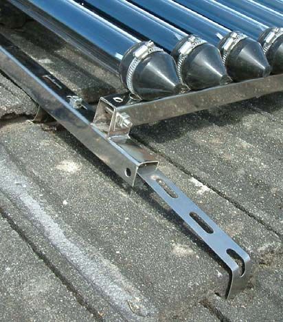
Ensure that the immersion heater (if fitted) is isolated. This should be controlled by a double-pole
isolator and locally fused at 13A unless supplied via a dedicated 16A circuit breaker in the
                              consumer unit. Turn off the main
                              electrical supply whilst disconnecting
                              and temporarily fit a fully insulated
                              terminal block or junction box on the
                              free cable end, before turning the
                              power back on.
                                   Whilst the main cylinder was
                                   draining, the primary coil pipework
                                   was also drained, disconnected, and
                                   the pipes capped. I had originally
                                   installed gate valves to the coil
                                   making this job simple, allowing the
                                   central heating system to continue in
                                   operation. These valves had remained
                                   free in operation due to the use of
   Original installation water     Fernox MB1 corrosion inhibitor in            Original heating pipework
         feed pipework                                                                and controls
                                   the central heating system.
                                                     Once the upper part of the cylinder is drained, the
                                                     top connection and pipework can be removed. The
                                                     new cylinder is taller so this had to be replaced
                                                     anyway.
                                                     After removal of the old cylinder, for easier access
                                                     the new ball valves were fitted to the tank feeds
                                                     and TMV pipework installed, before placing the
                                                     solar cylinder in position. With the cylinder feed
                                                     valve turned off, the header tank was refilled whilst
                                                     the remaining cylinder pipework was completed.
                                                     This also allowed the cold services from the tank
                                                     (e.g. toilets) to be brought back into operation.
                                                     With new cylinders, it is sensible to refill slowly
                                                     under control of the cold feed valve. I fit the
                                                     immersion heater at the last moment – using the
                                                     immersion hole to view the water level. Why?
                                                     Because new cylinders can (and do) sometimes
                                                     leak – they hold a lot of water, and remember how
                                                     long it took to drain down the original! Fill the
                                                     cylinder to just above each union connection at a
                                                     time - simply to ensure there are no seeps. If all is
                                                     OK, screw in the immersion heater and open the
                                                     valve fully.
                                                     With ball valves fitted to the outlets from the
                                                     cylinder, flushing the pipework to the TMVs is
                                                     simple. This must be carried out prior to final fit of
                                                     the TMVs, otherwise any warranty will be void.
  New valve gear and TMVs – part of solar filling-   After fitting the TMVs, vent the pipework to each
    loop and Pressure Regulating Valve at top
                                                     hot tap. Reconnect the electrical cable to the

                                                      4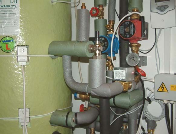
immersion heater (with the same caveats as in disconnection above), as the immersion is required
for hot water until the coil connections to the heating system are replaced.
Note: I had a delayed drip from the lower cylinder feed. Tightening further made no difference
necessitating a cylinder only drain-down the following day. I resorted to placing PTFE tape around
the olive and threads prior to tightening. Whilst this should not be necessary, sometimes the brass
fittings on cylinders simply will not seal without extra help! If there is a leak, do not simply
continue tightening the union with ‘as much force as you can muster’. The union is brazed to what
is a very thin cylinder wall. Excess force may twist the union and irreparably damage the cylinder.
It is far better to seal the leak properly.

Boiler pipework
When originally installing the heating system in 1992/3, I created two individual heating circuits –
one for bedrooms and the other for the main living areas. The original reasoning behind this was to
make any future maintenance easier since one circuit could be isolated without killing the entire
system.
However the new requirements of Part-L of the Building Regulations require at least two
independent heating zones in all properties with over 150m2 floor area. Whilst not quite falling
within the floor area requirement at 142 m2, it now followed that fitting two motorised zone valves
onto these circuits, with individual time controls, would allow the bedrooms circuit to be shut-
down during the day – thereby further conserving fuel. My system retains a single programmable
room thermostat common to both radiator circuits but there is no reason why two room stats
                                                           cannot be used if they can be suitably
                                                           located. Remember that any radiator in
                                                           the room where the thermostat is
                                                           located must not be fitted with a TRV.
                                                           It should be fitted with lockshield
                                                           valves at both ends and adjusted during
                                                           system balancing to ensure that the
                                                           room is the last to reach the required
                                                           temperature.
                                                             A further requirement of Part-L, is the
                                                             fitting of an Automatic Differential
                                                             Pressure Bypass Valve (ADPBV)
                                                             between the pump flow feed and boiler
                                                             return. This allows a minimum water
                                                             flow through the boiler improving
                                                             efficiency. It also reduces the ‘whistle’
                                                             that can be sometimes be heard from
                                                             Thermostatic Radiator Valves (TRVs).
                                                             This occurs when the system is at full
                                                             temperature and the TRVs are shutting
                                                             down, increasing the flow pressure
                                                             from the pump. With an ADPBV, the
                                                             valve senses the rise in system
                                                             pressure, and ‘excess’ flow is allowed
                                                             to return back to the boiler; thus
                                                             maintaining a consistent flow rate and
                                                             higher return flow temperature.
     Completed boiler and solar pipework and flow controls

                                                      5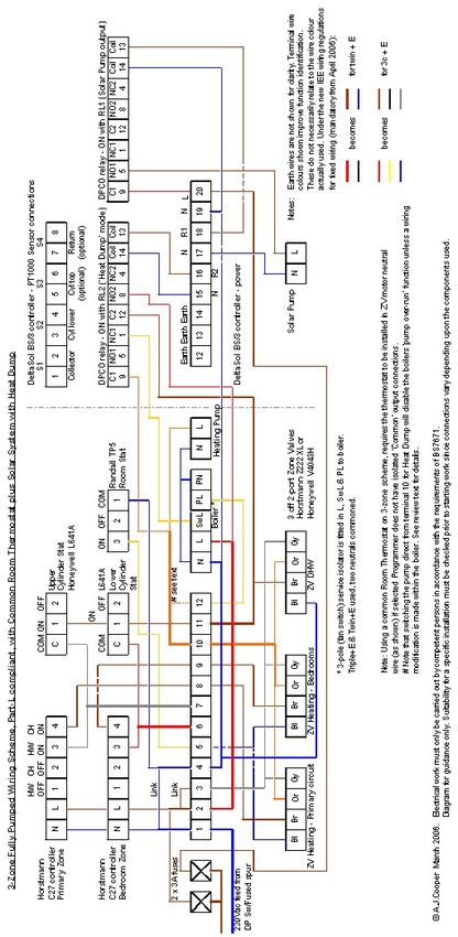
A disadvantage of extended radiator
                                                             pipe runs in large properties is that
                                                             when the cylinder thermostat ‘calls for
                                                             heat’, a significant proportion of the
                                                             boiler flow is diverted to the cylinder
                                                             heating coil. This lowers the radiator
                                                             temperatures, especially at the further
                                                             ends of pipe runs.
                                                               After musing this problem, I installed
                                                               an experimental solution utilising a
                                                               second ADPBV. A 15mm direct pipe
                                                               connection is used between the hot
                                                               water zone valve and cylinder coil,
                                                               with a 22mm pipe connection in
                                                               parallel - via an ADPBV. In theory,
       ADPBV detail on boiler coil – main system ADPBV in      with suitable setting of the ADPBV,
                     background (blue cap)                     around 75% flow can be maintained in
                                                               the radiator circuit(s) when the
cylinder is also heating. If the radiator circuit is off (or TRVs closing) the cylinder ADPBV will
open, allowing full 22mm pipe flow through the cylinder coil. This is effectively a variable
intelligent flow restrictor.
   Author’s notes:
   22nd April 2006 – this seems to work extremely well allowing adequate flows to all radiators
   whilst giving a minimal increase to the cylinder reheat time.
   19th June 2006 - In hindsight, I would have fitted the two cylinder thermostats 100mm
   higher; such is the efficiency of the system. It is also worth considering the option of a
   second boiler coil at higher level. This would have been better for early morning boiler top-
   ups on spring and autumn days when solar input takes longer due to variable British climate
   and weather conditions. The second coil would be fed via another 2-port zone valve
   controlled by a higher-level cylinder thermostat.

                                                 6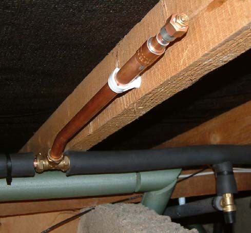
Solar Collector Assembly
The Navitron manual fully explains how to assemble the complete panel and there is no point in
reinventing the wheel. However, whilst it is a good idea to ‘trial fit’ a tube or two on the ground do
not be tempted to lift the completed panel onto the roof! Firstly it is a lot heavier when completed
than it looks, and secondly the tubes must not be fitted until the manifold and pipework is filled
with water and the pump and controller have been tested.

Solar Collector Installation
My installation is on a bungalow with a relatively shallow roof angle (approx. 23ºC). Therefore
access is easy and walking around on the tiles is relatively safe. However for steeper roof angles
and installations on houses the correct safe working equipment is vital. Hire an aluminium access
tower and roof ladder for a couple of days - the minimal cost is usually preferable to falling off the
roof! Also you ideally need a helper to pass tools and panel components up to you. Having to
continually climb up and down every time you realise you have forgotten a minor item is time
consuming and tiring.
One panel installation method, on a slate roof, is illustrated on the Navitron website. I chose to
vary the fixing method slightly as my concrete tiles are easily removable to locate the rafters. I
fixed the mounting straps directly to the rafters using two 8mm ‘coach’ screws on each strap
                                          before replacing the tiles. The solar panel frame is then
                                          bolted to the straps.
                                             Because I have relatively thick concrete roof tiles that
                                             hang on the battens, the frame needed ‘pulling-down’
                                             onto the tiles. Hence the mounting straps were bent to
                                             shape, attached to the rafters, and tiles replaced before
                                             the final fit of the manifold frame. The overlapping
                                             tiles needed to be lifted at least 25mm in order to slide
                                             back in the tile below – hence the need for the frame to
                                             be moveable until the tiles were refitted. Note how the
                                             top end of the strap passes under the tile above, thus
                                             being fixed securely at both ends.
                                          The only comment I would make is that no shake-proof
                                          (locking) washers were supplied with the mounting
                                          frame. From both an engineering and assembly
                                          perspective this is a shame, since it is difficult to get a
            Lower frame mounting          spanner under the frame channel section to hold the
                                          nuts secure when bolting the frame to the mounting
straps. This may not be a problem on a flatter slate or tiled roof as it would be easier to slide the
tiles under the pre-mounted frame. With hindsight, I would have obtained suitable locking washers
prior to assembly.
The tricky bit is cutting the pipe holes in the tiles - without breaking them. If you blast it with a
hammer drill, the most likely result will be a broken tile! Either use a masonry drill, at slow speed
without hammer action, or (as I did) use a TCT hole-saw intended for cutting stone/concrete.
Note: The grey water stain on the roof shots is not a leak – it was from run-off water that I used to
lubricate the cutter whilst drilling the holes – those tiles are hard!
The only question is what to do regarding insulating the elbows and pipes exiting the manifold.
These will freeze if left unprotected but pipe insulation is difficult to fix adequately on such a short
and elbowed length.

                                                   7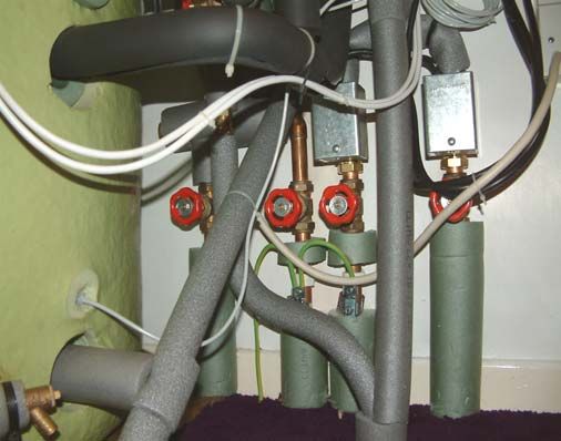
Also pipe lagging will degrade over time due to
exposure to the weather. A neater, more
permanent and reliable solution involves
modifying a couple of ABS electrical enclosures
of suitable size. The nearest I could find to the
manifold box section dimensions were stock
number 222-238 from RS Components - but they
will only supply to trade account holders. A hole
cut in two sides allows the base section of the box
to be fitted onto the end of the manifold. The
Right-hand end cap box internal view 15mm pipe passes through the base hole (slotted
to the box edge on final fitting to ease assembly)
and into the elbow. The box is held against the
manifold using a clamp-around 20mm cable
clamp of the type used for securing high current
armoured cables. After leak testing the elbow
joints, the pipes are lagged as normal. Then the
remaining interior space of the box is filled with
Rockwool loft lagging, in much the same way as
the manifold itself. Similarly fill the lid section
with Rockwool before screwing it in place – be
careful not to trap the manifold sensor cable.
The sensor cable is passed through a separate
5mm diameter hole, drilled slightly forward of the
Left-hand end cap box complete
main pipe hole. It is then sealed with silicone
sealant. This is preferable to using the pipe hole since the cable would be in direct contact with the
hot pipe, which may cause long-term degradation of the insulation – although the manifold sensor
is fitted with a silicone insulated cable (the black one).
Silicone sealant is also used to secure and seal the box to the manifold along the top, front and rear
edges. The bottom edge and exit slot hole were left to allow any water to escape should there be a
leak from pipework or the box seal.
It is a shame the manifold does not include a bespoke screw-on insulating cover kit. Mass-
produced insulated end covers should work out less than the £20 the boxes cost me and would be
well worth the minimal extra cost in terms of the extra insulation and protection offered.
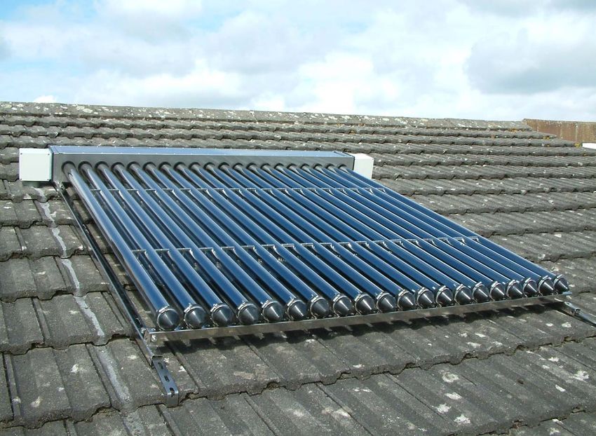
Although not carried out until later, it took about 1.5 hours to install all twenty tubes with
reflectors. I initially fitted two tubes at the sensor end of the manifold and used these to ensure that
the controller was working. Even two tubes were enough to raise the lower cylinder temperature
by 4ºC in two hours with relatively overcast sky. The last thing you need is to have to remove the
tubes again because there is a control or water circulation problem.
8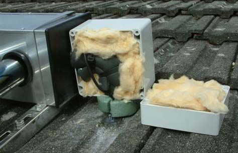
The installed solar panel complete

                9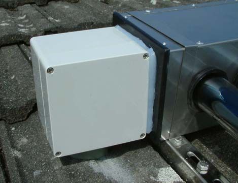
Solar Pipework
The basic plumbing schematic is illustrated in the Navitron manual. The only
major deviation was the position of the one-way valve. Because this item
contains plastic components that could be affected by extreme temperatures, I
located it in the cooler return pipe - ensure it is fitted the correct way around!
It is essential to fit an automatic Pressure Relief Valve (PRV) to the system. I
used a 1.5 bar expansion vessel (Cal-Pro) and therefore a non-adjustable 3 bar
PRV was used. This later proved to be the source of a problem during initial
filling, as the system was continuously losing pressure. No leaks could be
found until I realised that the overflow pipe was dripping continuously into
the tundish/down-pipe. Manual operation of the valve failed to flush the
problem away. Resorting to removing the valve revealed a curly length of
brass swarf underneath the valve seat! This was carefully removed and the
valve refitted. The system then held pressure with no further problems. It is
likely that swarf was within the fitting from new, left from the manufacturing

process. I was thankful for using a compression fitting on one side of the BSP               Tundish
                                                         threaded PRV to allow easy removal.
                                                         The other requirement is the ability to bleed air
                                                         from the system pipework. The air vent is
                                                         recommended to be “at the highest point in the
                                                         system”. This makes sense, as air will always
                                                         rise to the highest point it can find. However
                                                         placing the vent externally on the manifold
                                                         gives rise to the problem of having to “nip up
                                                         on the roof to check for trapped air” – not very
                                                         practical!
                                                         However in practice, any air trapped within the
                                                         manifold should be carried out around the
                                                         pipework. Therefore I elected to fit an air trap
                                                         inside the loft. The flow pipe bends down to the
                                                         left of the photo, before bending up through the
                                                         roof into the manifold. Therefore the horizontal
  Flow pipe air vent detail and pressure relief valve    pipe run shown here is still physically higher
                                                         than the manifold outside on the roof.
The air trap consists of a 22mm compression Tee with reducing sets on the 15mm flow pipe
connections. A 22mm pip rises from the ‘Tee’ to an air bleed at the top of the picture. The air
bleed itself is a radiator type soldered directly to the pipe. Unfortunately I did not have the
appropriate fitting to directly solder the vent to the 22mm pipe, hence the triple stage conversion!
The remaining pipework and the relief valve body was lagged after the photo was taken. (The
lower green Climaflex-lagged pipe is the hot water expansion pipe from the cylinder.)
This vent worked extremely well for system filling and all remaining air was trapped and released
from the pipework within the first ten minutes of running the pump.
Warning: Do not use conventional automatic air vents intended for central heating systems. These
contain plastic components and are only rated at 90ºC to 110 ºC and will melt under fault
conditions. Remember that the system is pressurised, so the boiling pint of the water is raised well
above 100ºC. Caleffi Solar manufacture an automatic air vent capable of 150ºC – but at £18 why

                                                        10
bother? Once the main air is vented, the air trap shown here will collect all remaining residual air
bubbles.
There is also a vertical vent on the flow pipe into the cylinder coil. This is primarily used to vent
air from the coil during system filling – although it does provide a secondary air trap during
system operation.
The solar manifold connections were made using 22mm compression elbows with reducing sets to
connect to the 15mm flow and return pipes. Use a small amount of pipe sealant (such as Fernox
“Water Hawk”) on all compression fittings and reducing sets. As the system is pressurised, this
will help to seal any minute imperfections in mating surfaces that may otherwise cause slight
leaks. It is worth checking the tightness of all compression joints a day or two after completion.
They tend to ‘settle’ and it is surprising how slack a joint may feel the following day – despite how
tight is seemed when first done up!
It is preferable to use a pipe-bender wherever possible because each elbow fitting used adds a
greater restriction to the flow rate. With practice, multiple bends are possible, thus minimising the
use of fittings and reducing the chance of leaks later.
Use lead-free solder with appropriate flux on all soldered pipework connections as it has a higher
melting point than leaded solder. (If higher pressures are used, under extreme fault conditions it is
conceivable that the circulating water could reach the 180ºC melting point of leaded solder).
Author’s note: Subsequent experience has shown that for domestic installations, micro-bore
10mm diameter flow and return pipe is better suited for the solar pipework. It reduces the
system water content and, being flexible, is easier and quicker to install.
System Filling
It is essential to flush the pipework to remove all traces of flux and debris from the system. Fill the
system via the filling-loop, venting air as necessary. Use the manual knob on the PRV to flush the
top end of the pipework via the overflow pipe. Closing a pump valve will force the water up and
through the manifold to flush the upper pipework. Flush the cylinder coil and flow pipe using the
drain-off in the return pipe.
At this stage it is worthwhile testing the pump and checking all pipe joints for leaks. Then drain
the solar pipework into a bucket. Why? Because you need to know how much water content is in
the system, in order to calculate the correct quantity of antifreeze to add… (My system contained
just over five litres of water.)
I used Fernox ’Alphi-11’ a combined anti-freeze with
corrosion and limescale preventer. I had initially
intended to infuse the Alphi-11 by removing the
vertical vent pipe from the Tee on the cylinder coil
flow pipe and adding it directly into the coil – then
simply fill the remaining system with water via the
filling loop. Unfortunately the anti-freeze, being
somewhat thicker than water, refused to flow into the
pipe. It was sufficiently thick to cause an air lock in
the temporary tube and funnel I was using. After
some head scratching, I created (i.e. bodged) a
makeshift adaptor for the filling-loop using a plastic
The bodged, and efficient, ways to add anti-freeze drinks bottle and a ½” bsp male compression adaptor
sealed in the bottle neck.
11Following Ivan’s advice, I subsequently purchased a Hozelock Polyspray 3 – a two-litre garden
spray with flexible hose for £14. Adapted to fit the filling-loop using a 3/8”bsp to 15mm adaptor
fitting, this is a quick and mess-free way to pump anti-freeze into the system!
The actual quantity of antifreeze used depends on the desired protection temperature - the
percentages and protection levels are quoted on the product container. This will depend on location
and hence winter night-time temperatures, and also on the setting of the freeze protection
parameters OCF and CFR on the BS/3 controller.
Solar Controller and Sensors
The Resol DeltaSol BS/3 controller was selected because it incorporates a second relay output that
can be programmed to dump excess heat from the cylinder into the domestic heating system when
high solar energy input combines with periods of low hot water use. For instance, if you go on a
summer holiday and use no hot water for a fortnight, in all probability, the cylinder will reach the
maximum temperature programmed limit. The controller then shuts down, and is likely to cause
the manifold to boil and the system to vent excess pressure. If the solar tubes are regularly allowed
to continue heating with no water in the manifold, long-term damage or performance reduction to
the tubes could result. Whilst the Navitron tubes are relatively cheap to replace, the upgraded
controller and installation changes to accommodate a heat dump are cheaper!
To achieve the heat dump capability, additional modifications are required to the existing boiler
system wiring and pipework. The effort is worthwhile as it gives peace of mind and virtually
guaranteed trouble-free solar operation.
The DeltaSol controller uses Platinum Resistance Thermometer probes of nominal 1000 ohms
resistance at 0ºC; hence the term PRT1000. The black silicon lead version (FKP6) is intended for
the manifold, S1, whilst the grey lead FRP6 sensors are for the cylinder and return pipe sensors S2
to S4. These can be readily extended using any two-core wire and terminal block connector if
necessary - although I used genuine PRT extension cable and connector to extend S1.
PRT1000 sensors change resistance by 3.85ohms per ºC. Hence the 1000 ohm resistance will be
relatively unaffected by the extension wire resistance and hence no significant temperature error
will result.
It is worth checking the continuity of the sensors with a resistance meter
before fitting. At 20ºC the resistance should be 1077 ohms. Fit the probes
into their respective pockets using a small amount of heat conductive
paste (as supplied for the solar tube heat pipes). A blob of silicone sealant
will retain then in place.
If sensor S4 is used, this can be clipped to the surface of the return pipe
using 13mm spring tool clips (Farnell-In-One stock code 103-022). It is
not critical for S4 to be in the water flow and the additional compression
adaptors to enable this are not worth the effort. Pipe lagging will retain a
uniform sensor temperature.
The only potential reliability issue with the BS/3 controller is likely to
S4 mounting method come from the output switching relays (Finder type 34.51.7.012.0310)
after several years of use. (OK, as an Electronics Engineer, I often take a
peek inside electronic gizmos to inspect the design, manufacturing and soldering quality).
Switching inductive loads, like a pump, always results in long-term wear on switch contacts due to
arcing. Farnell-In-One stock codes 414-3103 or 414-3152 are equivalent replacements for the
relays. These cost under £5 each and can easily be changed by anyone with electronics repair
experience and, if necessary, is a far more economic repair than a new controller.
12However, for added reliability and peace of mind (read ‘over-engineering’), I elected to buffer
both solar controller relays with higher current versions. One relay was required in any case for the
heat-dump control via the BS/3 ‘R2’ output, so I used a second ‘slave relay’ for the solar pump via
output ‘R1’. The additional relays used were OMRON MY2-230V plug-in types, Farnell-In-One
186-284, mounted in a 529-734 DIN relay socket, retained with a pair of 103-923 clips. RS stock
codes for similar items are 488-1904, mounted in DIN-rail sockets 830-376. As plug-ins, these
relays are easily user replaceable in the event of failure and are mounted in the main wiring
terminal box. See Appendix A for system wiring diagram used.
Warning: Do NOT use a slave relay for any solar controller designed for speed control of the
solar pump. This includes the Resol BS/4 and the new Navitron TDC3.
Electrical Installation
Part-P of the new Building Regulations prohibits uncertified electrical work in certain areas
including addition of new circuits and work in bathrooms and kitchens. The latest amendment to
Part-P coming into force in April 2006 states under ‘Table 1, Additional note n’ that “New central
heating control wiring installations are notifiable even where work in kitchens and bathrooms is
avoided”. This is ambiguous in that installation of the solar system is an addition and/or
modification to the existing circuit and is not a ‘new installation’ as such. Modifications to existing
installations are permissible providing they do not include provision of a new circuit. Therefore
the effect of Part-P on a solar installation is debateable - since the electrical supply can be taken
from the existing feed for the central heating system or from the immersion circuit as required,
and, when linked to the existing heating system, is technically a ‘modification’. Check with your
Local Council Building Control to clarify your own situation before proceeding.
Where the heat-dump option is employed, as in this
example, it is essential that the solar controller be
powered from the same isolator as the central heating
system and boiler. Since the controls are electrically
interconnected, they must have a single common point
of isolation for safety.
The illustrated connection box replaced the original
Randall WC/3A wiring centre and was assembled using
industrial terminal components - although any
appropriately rated relays and terminal blocks are
Main wiring terminal and relay box for
combined heating and solar wiring su itable. As already stated, the solar pump relay is not
essential and was added for personal preference with a
view to long-term reliability. The important
regulatory point is that all mains
connections (and relays where used) must be
inaccessible without the use of a tool i.e.
they must be located behind the cover of a
box whose lid is only removable using a
tool (e.g. a screwdriver). Cable glands are
used to safely secure the flexible cables, the
fixed cables entering via cutouts and
protected by PVC mini-trunking. Two
3.15A fuses are also used – one each for the
solar and boiler system power. In addition to
Twin programmers and electrical control installation
fault protection, these also allow shutdown
of boiler or solar circuits individually for
13repair or maintenance. Note that these are in addition to the 5A fuse feeding the complete
installation via a switch-fused spur. A wiring diagram illustrating the connections for the
components used is shown in Appendix A.
Heat Dump Mode Operation Description
The Heat Dump is controlled from the BS/3 ‘R2’ output. When the cylinder reaches the limit
temperature set by parameter ‘AH0’, relay R2 will operate. This operates the ‘Heat Dump’ double-
pole-changeover type relay in the control box. With reference to Appendix A, it can be seen that
one pole is wired so as to open the ‘Domestic Hot Water’ motorised valve. In turn, the valve
initiates the central heating pump operation as normal. This circulates water around the boiler
circuit, ‘pulling’ heat out of the cylinder via upper the boiler coil. I also re-plumbed the bathroom
radiator direct to the boiler pump circuit to act as the dump load. Some systems may already be
configured this way.
Of course, under normal circumstances, the boiler would also fire at this point – which is clearly
undesirable since the object is to cool the cylinder, not heat it further. Therefore the normally-
closed contact on the second pole of the ‘Heat Dump’ relay is utilised to disable the “call-for-heat”
switched-live feed to the boiler. This prevents the boiler firing for as long as the Heat Dump mode
is in operation - the shut-off temperature being set by the BS/3 ‘AHF’ parameter.
It is highly unlikely that the central heating
would be required at the same time as the heat
dump is operational but clearly the cylinder
would also dump into the heating circuit if the
room thermostat were calling for heat at the
same time.
I also modified the pipework to the bathroom
radiator so as to connect it directly to the
boiler circuit independent of the heating zone
valves. This means that this radiator will act
as a dump load but also will get hot whenever
the boiler is heating the hot water only (and
the central heating is off). In my case this is
Cylinder solar coil connections also showing 10mm desirable since the bathroom is on the north
pipes to bathroom radiator in foreground side and can feel cold, even in summer.
Important: The wiring method described inhibited the boilers ‘pump over-run’ function since the
boiler pump must be controlled direct from the Zone Valves. In my installation this is not a
problem, as the boiler has never been run hot enough for this to operate on a fully-pumped system.
Author’s note June 2008:
The latest versions of the System Wiring Scheme downloadable files are designed to maintain
the boiler pump over-run function and are suitable for all boilers employing a common neutral
connection between boiler and pump.
14Initial BS/3 Solar Controller Initial settings
With reference to the DeltaSol manual, the current parameters (as of June 08) set in the described
installation are programmed as follows:
Function Description Setting
Arr System mode Arr 2 (After-Heating mode)
OHQM Heat quantity balancing OFF
DTO Switch-on temperature 7.5K
DTF Switch-off temperature 4.5K
SMX Maximum Store temperature 75ºC
EM Collector safety limit temperature 130ºC
OCX System cooling function ON
CMX Maximum collector temperature 115ºC
OCN Minimum collector protection function ON
CMN Minimum collector temperature 18ºC
OCF Collector anti-freeze function ON
CFR Freeze protection operating temperature 1.5ºC
OREC Re-cooling function OFF
OTC Collector special tuning control function OFF
AHO Heat dump mode ON temperature 69.5ºC
AHF Heat dump mode OFF temperature 69.0ºC
HAND Operating mode AUTO
HND1 Relay 1 mode AUTO
HND2 Relay 2 mode AUTO
LANG Language En
The ∆T values DT0 and DTF set the temperature differential in degrees between collector and
cylinder temperatures. The Kelvin K unit was initially confusing but effectively the value can be
taken to be in degrees C. (since the Kelvin temperature scale is incrementally identical to
Centigrade except that it is offset by -273ºC).
The higher the DT0 value, the higher the temperature difference between manifold and cylinder
before the pump turns on.
Increasing the difference between DT0 and DTF will increase the pump run time. Similarly
lowering the DTF turn-off value will extend the time taken to cool the manifold to the turn-off
temperature difference. Be aware that too low a value for DTF may cause the pump to run
continuously in warm weather. There is a trade-off between higher differential temperature (giving
a higher rate of heat transfer) and the electrical (pump) energy consumption. Arguably it is more
efficient to allow the manifold to heat up, dump that heat into the cylinder and then shut-off to
repeat the manifold heating cycle. But a higher manifold differential takes longer to heat the
manifold between pump runs, therefore less thermal energy may be transferred.
Higher values for DTO (8K-12K) improve efficiency where there are long pipe runs between the
solar panel and cylinder. This helps to overcome the increased thermal losses on the pipework.
This system was run for the first year with DTO=5.5K and DTF=3.5K with the solar pump logging
a total run-time of 1180 hours and the Heat Dump 6 hours. The DTO and DTF values have now
been increased as in the table above for a comparison over the next twelve months.
Note: The BS/3 controller uses the upper cylinder temperature sensor to detect the AHF Heat
Dump shut-off temperature. This is somewhat wasteful of solar generated heat since the lower
cylinder needs to be reduced to around 59ºC (on my cylinder, with AH0 = 67.5ºC and AHF =
67.0ºC) in order to ‘pull’ sufficient heat from the top of the cylinder for S3 to detect a drop change
15of 0.5ºC. As a result, the dump radiator will be hot for a considerable time. To minimise the dump
run time it is essential that the difference between AHO and AHF is only 0.5ºC. Important: Ensure
that any thermostatic valve fitted to a single bypass Heat Dump radiator is set to maximum during
summer!
Summary
Installation was as easy as expected, despite the fact that this was my first solar system installation.
Providing the concepts of solar heating and the safety requirements of pressurised heating systems
are understood, the installation of a solar system is no more difficult than any other central heating
or plumbing job.
As of May 6th 2006 the system has been fully operational for a month or so. On cloudy, overcast
days, the system reliably raises the lower cylinder temperature to around 35ºC – despite drawing-
off hot water during the day. Thus in cloudy conditions, the cylinder still requires a ‘top-up’ from
the boiler first thing in the morning.
Whilst 35ºC is not hot enough to use direct from the tap, it must be remembered that it is creating a
major reduction in the quantity of heat input required from the boiler to finish raising the water to
a useable temperature. Hence even with no sunshine, savings are still being generated.
Intermittent or hazy sunshine reliably achieves a lower cylinder temperature of around 42ºC.
The first continuously sunny day since installation occurred on 5th May 2006. The cylinder peaked
at 62ºC at the top and 58ºC at the bottom. It provided ample hot water for two baths, one shower,
one washing machine run - and several lots of washing up! The boiler did not cut-in all day.
As June progressed into July, the boiler was redundant for all but a few dull/rainy days.
After a one-week holiday at the end of June, the controller logged three hours run-time on the Heat
Dump circuit (with AHO originally set to 67.5ºC).
This clearly demonstrates the efficiency of the Navitron system, and justifies the decision to install
the Heat Dump capability for non-use (holiday) periods.
I am seriously impressed with the effectiveness of the system, even in cloudy conditions. Navitron
provide a top grade evacuated tube solution at less than the cost of a flat plate collector system.
Even if you are not able to DIY, the fully installed cost ensures you are not fleeced for “going-
green”. Unlike higher priced competitors, there is a foreseeable payback period with the Navitron
system; and you are helping the environment and your reducing gas bill in the process.
Of all the renewable energy systems, solar water heating is by far the most cost effective. Navitron
have brought the prospect of renewable energy within the economic grasp of everyone.
16References
Navitron Ltd: http://www.navitron.org.uk/ Lands End Way, Oakham, Rutland, LE15 6RB. Tel.
01572-725512. Fax 01572-724390
Screwfix Direct: http://www.screwfix.com/ Screwfix Direct, FREEPOST, Yeovil, BA22 8BF.
Tel. 0500-414141
Plumbworld: http://www.plumbworld.co.uk/ Plumbworld.co.uk Ltd, 2, Millenium Court,
Enterprise Way, Evesham, Worcestershire WR11 6GS
BES Ltd. http://www.bes.co.uk/ Unit 3, Junction 6 Industrial Park, Electric Avenue,
Birmingham, B6 7JA 0800-801090 / 0121-322-6400
Newark Copper Cylinder Co. Ltd: http://www.newarkcyl.freeserve.co.uk/
Resol GmbH: http://www.resol.de/en/index.html
Horne Engineering Ltd: http://www.horne.co.uk/ 01505-321455
Armaflex: Armacell UK Ltd. http://www.armacell.com/uk
Climaflex: http://www.climaflex.com
Fernox: http://www.fernox.com
Building Regulations (Part L and Part P) can be downloaded from:
http://www.planningportal.gov.uk/approveddocuments
17Appendix A
The wiring diagram specific to components used in this project, based on the Honeywell S-Plan Plus
system, is reproduced below from the Excel™ spreadsheet master. Updated files are available for
customising if required including alternative options for S-Plan and Y-Plan schemes. Do NOT use a
slave pump relay on solar controllers capable of speed controlling the pump.
18Update – April 2007
The system has now been in operation for a full year and the fourth-quarter gas bill since installation
has been received. This allows a direct ‘before and after’ comparison to be made.
Gas consumption reduced by 5,400kWh in the year April 06 – March 2007. This equates to
approximately 23% saving over the previous 2005-06 period. The savings over previous years is
slightly higher but it must be remembered that UK winters are tending to become warmer so reduced
use of central heating in the winter quarters must be taken into consideration when lauding the savings.
Actual cost savings worked out to around £120 year-on-year. But is must also be considered that as part
of the package, I spent a further £300 updating the existing CH/DHW controls to meet full Part-L
specification. Hence not all the savings can be attributed to the solar installation.
This saving also occurred during one of the hottest summers on record and when the gas prices were at
their highest. Even compensating for these factors, it is still a very worthwhile return.
Putting this into context (for anyone sceptical about spending £1,200-£1,500 to upgrade their system), a
£120 return on a £1,500 investment over 12 months equates to an interest rate of 8% tax free. To
achieve this sort of return you would either need to invest the same amount in an ISA at 8% or in a
taxable account paying 10% gross – try doing that in your High Street Building Society!
© Anthony Cooper March 2006 – June 2008
19You can also read