USE AND MAINTENANCE MANUAL - GB - Fiac
←
→
Page content transcription
If your browser does not render page correctly, please read the page content below
GB

           USE AND MAINTENANCE MANUAL
                SILENT ELECTRIC ROTARY SCREW COMPRESSORS

WARNING: Read this manual carefully and in full before using the compressor.

                                                    1/68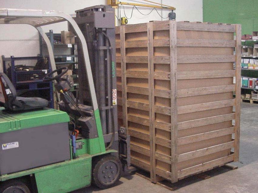
IMPORTANT INFORMATION
Read all the operational instructions, safety recommendations and all warnings provided in the instruction manual.
Most accidents encountered when using the compressor are merely due to the failed observance of basic safety
standards.
Accidents are prevented by foreseeing potentially hazardous situations and observing the appropriate safety
standards.
The fundamental safety standards are listed in the “SAFETY” section of this manual and also in the section involving
the use and maintenance of the compressor.
Hazardous situations to be avoided in order to prevent serious personal injuries and machine damages are listed in
the “WARNINGS” section of the instruction manual or are actually printed on the machine.
Never use the compressor improperly but only as recommended by the Manufacturer.
The Manufacturer reserves the right to up-date the technical information given in this manual without notice.

                                                        2/68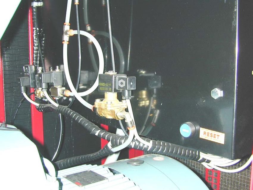
INDEX       I    GB

I   Index

0   Foreword ......................................................................................... 5
    0.1      How to read and use the instruction manual ............................................. 5
    0.1.a    Importance of the manual ....................................................................................................           5
    0.1.b    Conserving the manual ........................................................................................................          5
    0.1.c    Consulting the manual .........................................................................................................         5
    0.1.d    Symbols used ........................................................................................................................   6

1   General information........................................................................ 7
    1.1      Identification data of the manufacturer and the compressor ................... 7
    1.2      Information on machine technical/maintenance service .......................... 7
    1.3      General safety warnings .............................................................................. 7

2   Preliminary machine information ................................................ 10
    2.1      General description .................................................................................... 10
    2.2      Intended use ................................................................................................ 10
    2.3      Technical data ............................................................................................. 11

3   Transport, Handling, Storage ...................................................... 12
    3.1      Transporting and handling the packed machine ..................................... 12
    3.2      Packing and unpacking .............................................................................. 12
    3.3      Storing the packed and unpacked compressor ....................................... 13

4   Installation ..................................................................................... 14
    4.1      Admitted surrounding conditions ............................................................. 14
    4.2      Space required for maintenance ............................................................... 14
    4.3      Positioning the compressor ...................................................................... 15
    4.4      Connecting the compressor to the sources of energy and relative inspections 16
    4.4.1    Connecting the compressor to the electrical mains power supply ................................ 16
    4.4.2    Connecting the dryer to the electrical mains ................................................................... 18

5   Using the compressor .................................................................. 19
    5.1      Preparing to use the compressor .............................................................. 19
    5.1.1    Operational principle .......................................................................................................... 19
    5.1.2    Compressor operation with inverter versions “SD” (speed driven) .............................. 19
    5.2      Controls, indicators and safety devices of the compressor ................... 20
    5.2.1    Control panel ....................................................................................................................... 20
    5.2.2    Auxiliary control devices .................................................................................................... 21
    5.2.3    Description of the Electronic Control Unit ....................................................................... 21
    5.3      Check the efficiency of the safety devices before starting ..................... 30

                                                                3/68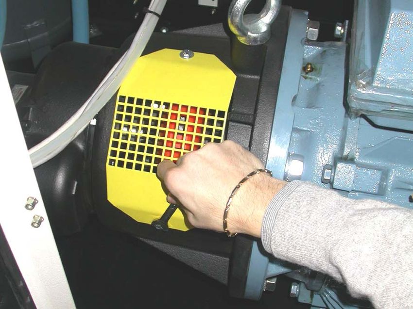
GB   I   INDEX

     5.4         Starting the compressor............................................................................. 29
     5.5         Stopping the compressor .......................................................................... 30

6    Compressor maintenance............................................................ 31
     6.1         Instructions relative to inspections and maintenance jobs. ................... 31
     6.1.1       Changing the oil ..................................................................................................................              33
     6.1.2       Replacing the oil filter cartridge ........................................................................................                      34
     6.1.3       Replacing the filter cartridge of the oil separator ............................................................                                 34
     6.1.4       Replacing the air filter cartridge ........................................................................................                      35
     6.1.5       ..............................................................................................................................................   35
     6.1.6       Cleaning the air/oil radiator ................................................................................................                   36
     6.7.7       Cleaning the dust-removal pre-filter .................................................................................                           36
     6.1.8       Grease the bearings of the motor......................................................................................                           36
     6.1.9       ..............................................................................................................................................   37
     6.1.10      ..............................................................................................................................................   37
     6.1.11      ..............................................................................................................................................   38
     6.2         Diagnosing the alarm status/inconveniences-faults ............................... 38

7    Drawings and diagrams ............................................................... 41
     7.1         Wiring diagrams .......................................................................................... 41
     7.2         Pneumatic diagrams ................................................................................... 46
     7.3         Maintenance schedule

                                                                        4/68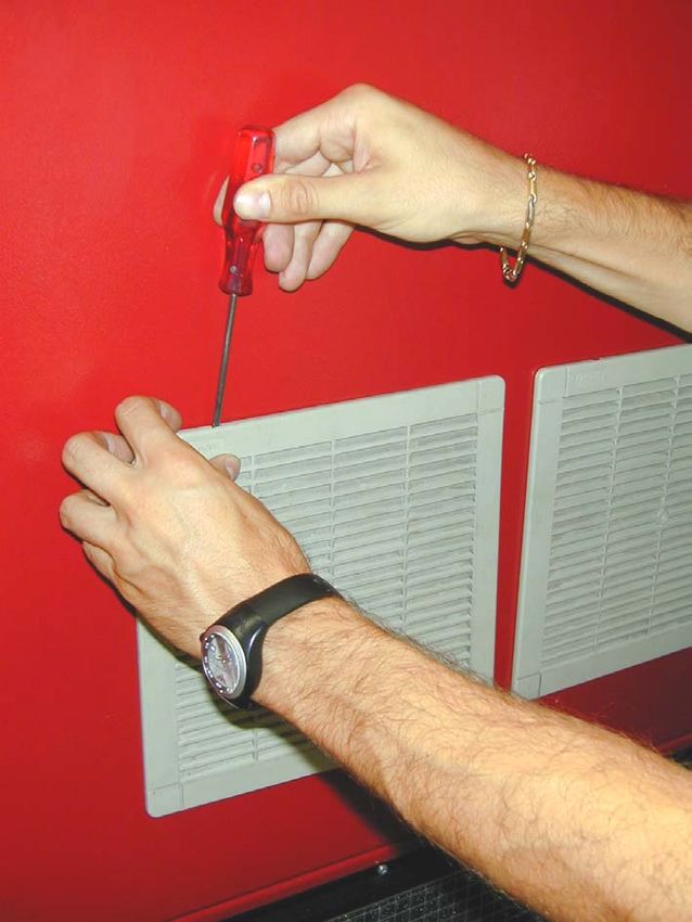
FOREWORD     0    GB

0       Foreword
0.1     How to read and use the instruction manual

0.1.a   Importance of the manual

        This INSTRUCTION MANUAL has been written to guide you through the INSTALLATION, USE and
        MAINTENANCE of the compressor purchased.
        We recommend that you strictly observe all the indications given within as the ideal operational efficiency
        and lasting wear of the compressor depend on the correct use and methodical application of the
        maintenance instructions given hereafter.
        Remember that when any doubts or inconveniences arise it is a good rule to always contact the
        AUTHORISED SERVICE CENTRES. They are at your complete disposal for any explanations or jobs
        required.
        The Manufacturer therefore declines all liabilities regarding the incorrect use and poor maintenance of the
        compressor.
        The INSTRUCTION MANUAL is integral part of the compressor.
        Ensure that any up-dates forwarded by the Manufacturer are actually added to the manual.
        If the compressor is sold on at a later date the manual must be given to the new owner.

0.1.b   Conserving the manual

        Use and read the manual with care being careful not to damage any part of it.
        Do not remove, tear or re-write any parts of the manual for any reason whatsoever.
        Keep the manual in a dry and sheltered place.

0.1.c   Consulting the manual

        This instruction manual is made up of the following:

        •   FRONT COVER WITH MACHINE IDENTIFICATION
        •   DETAILED INDEX
        •   INSTRUCTIONS AND/OR NOTES ON THE COMPRESSOR

        The model and serial number of the compressor to which the manual refers and that you have purchased
        is found on the FRONT COVER.
        The various SECTIONS in which all the notes relative to a certain subject are found in the INDEX.
        All the INSTRUCTIONS AND/OR NOTES ON THE COMPRESSOR aim at pointing out safety warnings and
        procedures required to use the compressor correctly.

                                                      5/68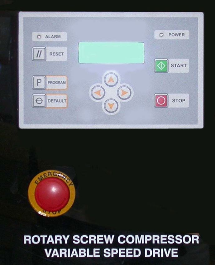
GB     0   FOREWORD

0.1.d   Symbols used

        The SYMBOLS pointed out below are used throughout this manual and their purpose is that of drawing the
        operator’s attention, informing the latter how to behave and how to proceed in each operational situation.

                        READ THE INSTRUCTION MANUAL
                        Read the use and maintenance manual carefully before installing and starting the
                        compressor.

                        GENERAL HAZARDOUS SITUATION
                        An additional note will point out the type of hazard involved.
                        Meaning of the indications:

        Warning!        This points out a potentially hazardous situation, which if ignored, could cause personal
                        injury and machine damage.

        Note!           This enhances crucial information.

                        RISK OF ELECTRIC SHOCK
                        Warning: the electrical power supply of the compressor must be disconnected before doing
                        any jobs on the compressor.

                        RISK OF SCOLDING
                        Warning: be careful when touching the compressor as some parts of it could be very hot.

                                                      6/68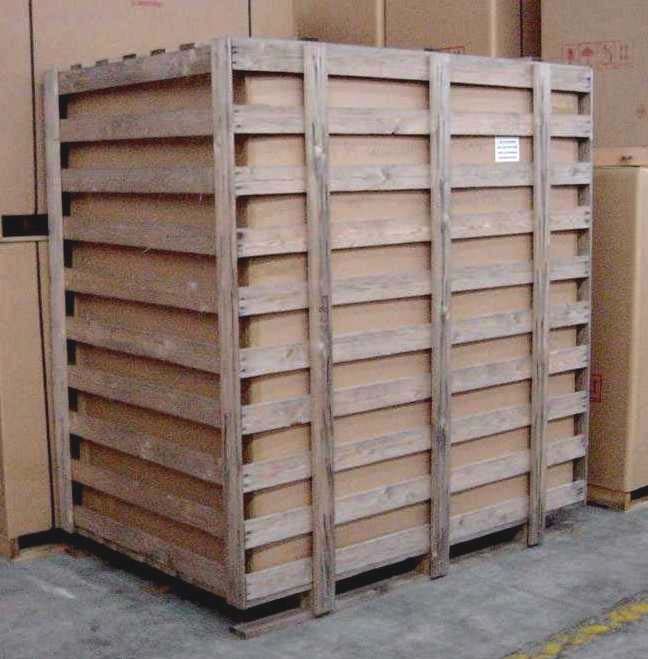
GENERAL INFORMATION      1   GB

1     General information
1.1   Identification data of the manufacturer and the compressor

      COMPRESSOR
      IDENTIFICATION
      NAMEPLATE (Example)

                                                                                 Silent electric rotary screw
                                                                                 compressor.

1.2   Information on machine technical/maintenance service

      We remind you that our technical service department is at your complete disposal to help you resolve any
      problems that may possibly be encountered, or to provide you with any other information necessary.

      In the case of need contact:

                      Our CUSTOMER TECHNICAL SERVICE department or your local dealer.

      The constant and efficient performance of the compressor is ensured only if original spare parts are used.

      We recommend therefore that you strictly observe the indications provided in the MAINTENANCE section
      and to use EXCLUSIVELY original spare parts.

      The use of NON ORIGINAL spare parts automatically annuls the guarantee.

1.3   General safety warnings

      Note!           The procedures provided in this manual have been written to assist the operator
                      throughout the use and maintenance of the compressor.

                      IMPORTANT INSTRUCTIONS FOR THE SAFE USE OF THE COMPRESSOR

      WARNING: THE INAPPROPRIATE USE AND POOR MAINTENANCE OF THIS COMPRESSOR MAY
      CAUSE PHYSICAL INJURY TO THE USER. YOU ARE RECOMMENDED TO CAREFULLY FOLLOW
      THE INSTRUCTIONS PROVIDED HEREAFTER TO AVOID SUCH RISKS.

      1. DO NOT TOUCH MOVING PARTS
      Never put your hands, fingers or other parts of the body near moving parts of the compressor.

                                                    7/68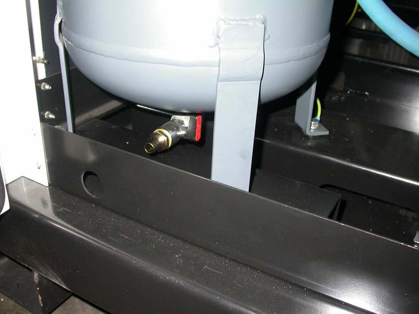
GB   1   GENERAL INFORMATION

     2. NEVER USE THE COMPRESSOR WITHOUT THE SAFETY GUARDS FITTED
     Never use the compressor without all the safety guards fitted perfectly in their correct place (i.e. panelling,
     belt guard, safety valve). If these parts are to be removed for maintenance or servicing purposes, ensure
     that they are put back in their original place perfectly before using the compressor again.
     3. ALWAYS WEAR SAFETY GOGGLES
     Always wear goggles or equivalent eye protection means. Never direct compressed air towards any part of
     your body or that of others.
     4. PROTECT YOURSELF AGAINST ELECTRIC SHOCKS
     Avoid accidentally touching the metal parts of the compressor with your body, such as pipes, the tank or
     metal parts connected to earth. Never use the compressor where there is water or in damp rooms.
     For SD versions: Switch the electric control panel off and wait five minutes before removing the protection
     guards of the inverter to avoid possible electrical shocks. Using special testers, always ensure there is no
     voltage on the parts on which you are about to work.
     5. DISCONNECT THE COMPRESSOR
     Disconnect the compressor from the electric power supply and completely discharge the pressure from the
     tank before carrying out any service, inspection, maintenance, cleaning, replacing or inspection jobs of each
     part.
     6. ACCIDENTAL START-UP
     Never move the compressor while it is connected to the electrical power supply or when the tank is
     pressurised. Ensure that the main switch is turned OFF before connecting the compressor to the electrical
     power supply.
     7. STORE THE COMPRESSOR APPROPRIATELY
     When the compressor is not in use, it must be stored in a dry room away from atmospheric agents. Keep
     it out of children’s reach.
     8. OPERATIONAL AREA
     Keep the work area clean and remove any tools that are not required. Keep the work area sufficiently
     ventilated. Never use the compressor in the presence of flammable liquids or gas. The compressor may
     produce sparks while running. Do not use the compressor where there may be paints, gasoline, chemical
     compounds, glues and any other flammable or explosive material.
     9. KEEP THE COMPRESSOR OUT OF CHILDREN’S REACH
     Prevent children or anyone else from touching the power supply cable of the compressor. All outsiders must
     be kept at a safe distance from the operational area.
     10.WORK CLOTHES
     Do not wear unsuitable clothing, ties or jewellery as these may get caught up in moving parts. Wear caps
     to cover your hair if necessary.
     11.PRECAUTIONS FOR THE POWER SUPPLY CABLE
     Do not disconnect the power supply plug by pulling on the cable. Keep the cable away from heat, oil and sharp
     edges. Do not stand on the electrical cable or squash it under heavy weights.
     12.LOOK AFTER THE COMPRESSOR WITH CARE
     Follow the maintenance instructions. Inspect the power supply cable on a periodic basis and if damaged it
     must be repaired or replaced by an authorised service centre. Visually check the outside appearance of the
     compressor, ensuring that there are no visual anomalies. Contact your nearest service centre if necessary.
     13.ELECTRICAL EXTENSIONS FOR OUTDOOR USE
     When the compressor is used outdoors, use only electrical extensions manufactured for outdoor use and
     marked as such.
     14.WARNING
     Pay attention to everything you do. Use your common sense.
     Do not use the compressor if you are tired. The compressor must never be used if you are under the effect
     of alcohol, drugs or medicines, which could make you tired.
     15.CHECK FAULTY PARTS OR AIR LEAKS
     Before using the compressor again, if a safety guard or other parts are damaged, they must be checked
     carefully to evaluate whether they may operate as established in complete safety.
     Check the alignment of moving parts, hoses, gauges, pressure reducers, pneumatic connections and every
     other part that may be crucial for the normal operational efficiency of the compressor. All damaged parts
     must be properly repaired or replaced by an authorised service centre or replaced following the instructions
     provided in instruction manual.
     16.USE THE COMPRESSOR EXCLUSIVELY FOR THE APPLICATIONS SPECIFIED IN THIS
     INSTRUCTION MANUAL.
     The compressor is a machine that produces compressed air.
     Never use the compressor for purposes other than those specified in the instruction manual.
     17.USE THE COMPRESSOR CORRECTLY
     Operate the compressor in compliance with the instructions provided in this manual. Do not allow children
     to use the compressor or those who are not familiar with it.
                                                     8/68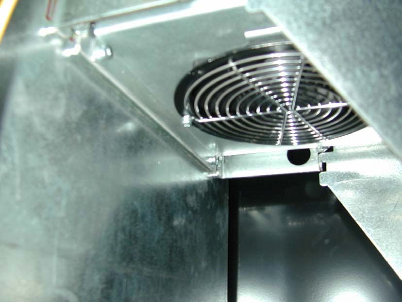
GENERAL INFORMATION      1    GB

18.ENSURE THAT EACH SCREW, BOLT AND GUARD IS FIRMLY SECURED IN PLACE.
19.KEEP THE IN-TAKE GRIDS CLEAN
Keep the motor ventilation grids clean. Regularly clean these grids if the work area is particularly dirty.
20.OPERATE THE COMPRESSOR AT THE RATED VOLTAGE
Operate the compressor at the voltage specified on the electrical data nameplate. If the compressor is used
at a higher voltage than that rated, the motor could damage or burn out.
21.NEVER USE THE COMPRESSOR IF IT IS FAULTY
If the compressor is noisy or vibrates excessively when running or it seems to be faulty, stop it immediately
and check its efficiency or contact your nearest authorised service centre.
22.DO NOT CLEAN PLASTIC PARTS USING SOLVENTS
Solvents such as gasoline, thinners, gas oil or other compounds that contain hydrocarbons may damage
the plastic parts. Clean them with a soft cloth and soapy water or other suitable liquids.
23.USE ORGINAL SPARE PARTS ONLY
The use of non-original spare parts involves the annulment of the guarantee and the abnormal running
conditions of the compressor. Original spare parts are available c/o the authorised dealers.
24.DO NOT MODIFY THE COMPRESSOR
Do not modify the compressor. Contact an authorised service centre for all repairs required. An unauthorised
modification may impair the efficiency of the compressor and may also cause serious accidents for those
who do not have the technical skill required to make such modifications.
25.TURN THE COMPRESSOR OFF WHEN IT IS NOT IN USE
When the compressor is not in use turn the main ON/OFF switch OFF (position “0”).
26.DO NOT TOUCH HOT PARTS OF THE COMPRESSOR
To avoid scolding do not touch pipes, the motor or any other hot part.
27.DO NOT DIRECT THE JET OF AIR DIRECTLY TOWARDS THE BODY
To avoid all risks never direct the jet of air towards people or animals.
28.DO NOT STOP THE COMPRESSOR BY PULLING ON THE POWER SUPPLY CABLE
Use the “O/I” (ON/OFF) switch to stop the compressor.
29.PNEUMATIC CIRCUIT
Use recommended pneumatic hoses and tools that can withstand the same or a higher pressure than the
maximum running pressure of the compressor.
30.SPARE PARTS
Use only original and identical spare parts to replace worn or damaged ones.
Repairs must be made exclusively by authorised service centres.
31.CORRECT USE OF THE COMPRESSOR
The operator must be perfectly familiar with all the controls and compressor characteristics before starting
to work with the machine.
32.MAINTENANCE JOBS
The use and maintenance jobs of the commercial components fitted on the machine, but not indicated in
this manual, are indicated in the enclosed documents.
33.DO NOT UNSCREW THE CONNECTION WHEN THE TANK IS PRESSURISED
Do not unscrew the connection for any reason whatsoever with the tank pressurised without first checking
if the tank is discharged.
34.DO NOT MODIFY THE TANK
It is prohibited to intentionally drill, weld or deform the compressed air tank.
35.IF THE COMPRESSOR IS USED FOR PAINTING JOBS
a) Do not work in closed rooms or near free flames.
b) Ensure that the room in which you are working is sufficiently ventilated.
c) Wear face and nose mask.
36.DO NOT PUT OBJECTS OR HANDS INSIDE THE PROTECTION GRID
Do not put objects or hands inside the protection grid to avoid physical and material damages.

                KEEP THESE USE AND MAINTENANCE INSTRUCTIONS CAREFULLY AND GIVE
                THEM TO PERSONNEL WISHING TO USE THE COMPRESSOR!

                WE RESERVE THE RIGHT TO MAKE MODIFICATIONS WHERE NECESSARY
                WITHOUT NOTICE

                                               9/68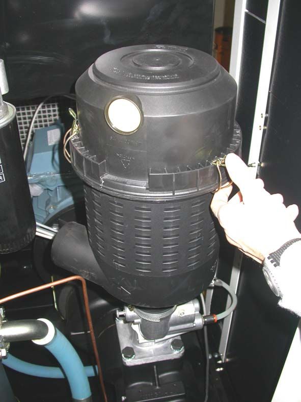
GB   2   PRELIMINARY MACHINE INFORMATION

2     Preliminary machine information
2.1   General description

      The rotary screw compressor has been specifically designed aiming at minimising maintenance and labour costs.
      The outside cabinet is completely covered in sound-proof and oil-proof panelling thus ensuring its extended and lasting wear.
      The components have been arranged so that all vital parts can be easily reached for maintenance purposes
      simply by opening dedicated panels with quick-release locking devices.
      The filters and adjustment and safety devices (oil filter, air filter, oil separator filter, regulator valve, minimum
      pressure valve, max. pressure safety valve, thermostat, belt tightener, screw compression unit, pressure
      switch and oil separator tank emptying and filling taps) are all fitted on the same side.

      Note!              The tanks of the compressors have been manufactured in compliance with the EEC/
                         404/87 Directive for the European market. The compressors have been manufactured
                         in compliance with the EC/37/98 Directive for the European market.

      Note!              Check your model on the identification nameplate fitted on the compressor. It is also
                         indicated in this manual.

      ADVISED LUBRICANTS
      Always use oil for turbines with approximately 46 cSt at 40°C and a pour point of at least -8 +10°C. The
      flash point must be greater than +200°C.
      The oil in rotary screw compressors has the function of lubricating and cooling the screw unit. The oil also
      has a sealing function to ensure a perfect compression seal within the block.
      Therefore it is extremely important to choose the correct type of oil for this type of compressor.

                         NEVER MIX DIFFERENT OIL QUALITIES.

      SCREW OIL FOR DR/SD VERSIONS
      FIAC        SYNT/RS D 46

      OR IN ALTERNATIVE
      SHELL       CORENA AS46
      MOBIL       RARUS SHC 1025

      OR 100% SYNTHETIC OIL WITH THE SAME TECHNICAL CHARACTERISTICS AS THOSE LISTED
      ABOVE

      Use oil with VG32 rating for cold climates and VG68 for tropical climates.
      It is advisable to use synthetic oils for very hot and humid climates.

2.2   Intended use

      The silent rotary screw compressors have been designed and manufactured exclusively to produce compressed air.
      EVERY OTHER USE, DIFFERENT AND NOT FORESEEN BY ALL INDICATED, RELIEVES THE
      MANUFACTURER OF POSSIBLE CONSEQUENT RISKS.
      In any event the use of the compressor different to that agreed in the purchase order RELIEVES THE
      MANUFACTURER FROM ALL LIABILITIES WITH REGARD TO POSSIBLE MATERIAL DAMAGE AND
      PERSONAL INJURY.
      The electrical system is not designed for the use in environments subject to explosion or for flammable products.

                         NEVER DIRECT THE JET OF AIR TOWARDS PEOPLE OR ANIMALS. NEVER USE
                         THE COMPRESSED AIR PRODUCED BY LUBRICATED COMPRESSORS FOR
                         RESPIRATORY PURPOSES OR IN PRODUCTION PROCESSES WHERE THE AIR IS
                         IN DIRECT CONTACT WITH FOODSTUFFS UNLESS IT HAS BEEN FIRST FILTERED
                         AND CONDITIONED FOR SUCH PURPOSE.

                                                           10/68
2.3 Technical data
Model HP40 HP50
Max. pressure bar/psi 8-116 10-145 13-188 8-116 10-145 13-188
Free air delivery ISO 1217 l/min 1260÷4840 1210÷4280 1160÷3750 2050÷5850 1900÷5270 1750÷4500
cfm 44÷171 43÷151 41÷132 72÷207 67÷186 62÷159
Air outlet fitting R 1” ½ G 1” ½ G 1” ½ G 1” ½ G 1” ½ G 1” ½ G
Lubricant qty l 51 51 51 51 51 51
Fan capacity m3/h
Oil residue in air ppm ≤1 ≤1 ≤1 ≤1 ≤1 ≤1
2-pole electric motor IEC
Output HP/kW 40/30 40/30 40/30 50/37 50/37 50/37
Protection rating IP 55 55 55 55 55 55
11/68
Service S1 S1 S1 S1 S1 S1
Max. starts per hour N°
Ambient temperature limits °C (min/max) 5/45 5/45 5/45 5/45 5/45 5/45
Noise level (2000/14/CE) dB(A) 67 67 67 69 69 69
Dimensions mm 1750 X 950 X 1700 1750 X 950 X1700
Weight Kg 980 1000
Sound level measured in a free range at a distance of 1 m: ±3dB(A) at the maximum working pressure.
The sound level may increase by 1 to 10 dB(A) depending on the room in which the compressor is installed.
Note! The technical data and dimensions of the machine are subject to variations at any time without notice
PRELIMINARY MACHINE INFORMATION
2
GBGB 2 PRELIMINARY MACHINE INFORMATION
3 Transport, Handling, Storage
In order to use the compressor in complete safety read the safety standards given
in section 1.3. before reading this section.
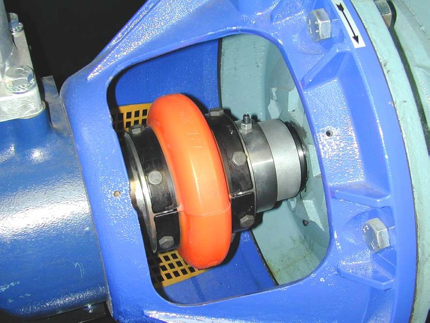
3.1 Transporting and handling the packed machine
The packed compressor must be transported by qualified personnel using a forklift
truck.
Before moving the machine ensure that the load-bearing capacity of the forklift truck is sufficient to take the
weight to be lifted.
Position the forks exclusively as illustrated below. Once the forks have been positioned in the points
indicated, lift slowly without jerking.
Never stand near the area where the compressor is being handled and never stand
on the crate while it is being moved.
3.2 Packing and unpacking
To avoid damages and to protect the compressor during transport it is usually placed on a wooden pallet,
to which it is secured by screws and covered with cardboard.
All the shipping and handling information and symbols are printed on the compressor packing. Upon
consignment remove the top part of the packing and check if any damages have been encountered during
transport. If any damages are found, caused during transport, immediately make a written claim, backed
up with photos of the damaged parts if possible and forward everything to your insurance company, with copy
to the Manufacturer and transporter.
12/68PRELIMINARY MACHINE INFORMATION 2 GB
Using a forklift truck take the compressor as near as possible to the place where it is to be installed then
carefully remove the protective packing without damaging it, following the instructions below:
• Remove the securing screws and open cage 1.
• Take the protective cardboard 2 off.
1
2
Note! The compressor can be left on the packing pallet to make it easier to move.
Carefully ensure that the contents correspond with all written in the consignment documents. Dispose of
the packing in compliance with current standards in force in the country of installation.
Note! The machine must be unpacked by qualified personnel using appropriate tools and
equipment.
3.3 Storing the packed and unpacked compressor
For the whole time that the compressor is not used before unpacking it, store it in a dry place at a temperature
between +5°C and + 45°C and sheltered away from weather.
For the whole time that the compressor is not used after unpacking it, while waiting to start it up or due to
production stoppages, place sheets over it to protect it from dust, which may settle on the components.
The oil is to be replaced and the operational efficiency of the compressor is to be checked if it is not used
for long periods.
13/68GB 4 INSTALLATION
4 Installation
In order to use the compressor in complete safety read the safety standards given
in section 1.3. before reading this section.
4.1 Admitted surrounding conditions
Position the machine as established when the order was placed. Failing this the Manufacturer is not liable
for any inconveniences that may possibly arise.
For SD versions, the cleanliness of the surrounding area is of extreme importance, as the
compressor is equipped with suction filters on the electric fan of the electric control panel.
Unless pointed out otherwise when placing the order, the compressor must work regularly in the
surrounding conditions indicated below:
ROOM TEMPERATURE
The room temperature must not be lower than 5°C or higher than 45°C to ensure the ideal operational
efficiency of the compressor.
If the compressor works at a room temperature lower than the minimum value, the condensate could be
separated within the circuit and therefore the water would mix with the oil, thus deteriorating the quality of
the latter, failing to guarantee the even formation of the lubricating film between the moving parts with the
possibility of seizure.
If the compressor works at a room temperature higher than maximum value, the compressor would take
in air that is too hot, which would prevent the heat exchanger from adequately cooling the oil in the circuit,
raising the working temperature of the machine, thus causing the thermal safety device to trip, which stops
the compressor due to an excessive temperature of the air/oil mixture at the screw outlet.
The inverter dissipator could overheat, causing it to stop (for SD versions).
The maximum temperature of the room is to be measured while the compressor is running.
LIGHTING
The compressor has been designed in compliance with legal prescriptions and in the attempt to minimise
shadow zones to facilitate the operator’s job.
The lighting system of the factory is to be considered as crucial for the operator’s safety.
The room in which the compressor is installed must have no shadow zones, dazzling lights or stroboscopic
effects due to the lighting.
ATMOSPHERE WITH RISK OF EXPLOSION AND/OR FIRE
The standard compressor is not pre-arranged or designed to work in rooms subject to the risk of explosion
or fire. The performance of the compressor may decrease at the maximum permitted ambient temperature,
with relative humidity higher than 80% and at an altitude of more than 1,000 mt.
For SD versions, the maximum relative humidity at all altitudes is 95% without condensation.
4.2 Space required for maintenance
The compressor must be installed in a large room that is well-aired, dust-free and sheltered away from rain
and frost. The compressor takes in a large amount of air that is required to ventilate it internally. A dusty
atmosphere would in time cause damages and inefficient performance.
Part of the dust once inside is taken in by the air filter causing it to clog rapidly and another part of dust will
settle on the components and will be blown against the cooling radiator, consequently compromising the
efficiency of the heat exchanger. It is therefore obvious that the cleanliness of the area in which the
compressor is installed is crucial for the correct efficiency of the machine, avoiding excessive running and
maintenance costs. To facilitate maintenance jobs and to create a favourable circulation of air, the
compressor must have a sufficient free space all around it (see fig.).
The room must be provided with outlets that lead outdoors near the floor and ceiling that will allow the natural
circulation of air. If this is impossible, some fans or extractors must be fitted to ensure an air flow rate 20%
higher than the cooling air flow rate. Minimum recommended fan capacity: 2500 m3/h.
14/68INSTALLATION 4 GB
1
H. min = 3500
200
min. 3200
min. 1000
2000
min. 5000
Ducts for the inlet and outlet of the air can be used in unfavourable environments. These ducts must be the
same size as the in-take and delivery grid. If these ducts are longer than 3 meters contact the Authorised
Service Centre.
Note! A conveyance system can be fitted to recover the hot ventilation air delivered, which
can be used to heat the room or for other purposes. It is crucial that the cross section
of the system that recovers the hot air is greater than the total cross section of the
grid slots plus the system must be equipped with a forced extraction system
(extractor fan 1) to favour a constant downflow. (minimum cross section 1200 cm²).
4.3 Positioning the compressor
Once the position in which the compressor is to be installed has been identified ensure that the compressor
is set on a flat surface.
No special foundations or bases are required for the machine.
Do not secure the compressor rigidly to the floor.
15/68GB 4 INSTALLATION
4.4 Connecting the compressor to the sources of energy and relative inspections.
4.4.1 Connecting the compressor to the electrical mains power supply
The compressor is to be connected to the electrical mains by the customer, to his
exclusive liability, employing specialised personnel and in compliance with the
Accident Prevention Norms EN 60204.
INSTRUCTIONS FOR CONNECTING TO EARTH
This compressor must be connected to earth while in use in order to safeguard the operator against
electrical shocks. The electrical connection must be carried out by a skilled engineer. It is advisable never
to dismantle the compressor or even to make any other connections. All repairs must be carried out
exclusively by authorised service centres or other qualified centres. The earth wire of the power supply
cable of the compressor must be connected only and exclusively to the PE pin of the terminal board of the
actual compressor. Before replacing the plug of the power supply cable ensure that the earth wire is
connected.
Avoid all risks of electrical shocks. Never use the compressor with damaged
electrical cables. Regularly check the electrical cables.
Never use the compressor in or near water or near a hazardous area where electrical
shocks may be encountered
ELECTRICAL CONNECTION
The three-phase compressors (L1+L2+L3+PE) must be installed by a qualified engineer. The three-
phase compressors are supplied without plug and cable. The power supply cable must be fed into the
electric cabinet through cable clamp 1 on the top of the electric cabinet.
1
Ensure that the cable cannot accidentally come into contact with moving or hot components, possibly
secure with clips. The cross section of the wires of the power supply cable (Install in open catwalks and
at maximum ambient temperature of 45°C) must be as follows:
Power Hp Rated voltage
480V 440V 380/415V 220/240V
40 25 mm2 50 mm2
50 25 mm2 70 mm2
You are recommended to install the socket and magnetothermal switch no further than 4 m from the
compressor. The required characteristics of the magnetothermal switch are given in the table that follows.
The fuses are already installed in the door locking switch and are the following type:
Power Hp Rated voltage
380/415V 220/240V
Magneto thermal switch Fuse Magneto thermal switch Fuse
40 100 A 100 A 160 A 160 A
50 125 A 125 A 200 A 200 A
16/68INSTALLATION 4 GB
for SD models:
Power Hp Rated voltage
380/415V 220/415V
Magneto thermal switch Fuse Magneto thermal switch Fuse
40 63A 100A / /
50 80A 125A / /
Note! The parameters of the magneto thermal switches refer to switches type K.
Ensure the installed power in kW is at least double the input of the electric motor, for SD models, the installed
power in kW must be the same as that absorbed by the compressor. All silent rotary screw compressors
avail of Star/Delta starting, which enables the motor to start with as little electrical energy consumption
upon start-up as possible.
The mains voltage must correspond with that indicated on the electrical data nameplate of the machine;
the admitted tolerance must remain within +/- 6%.
EXAMPLE:
Voltage, 400 Volt: minimum tolerance 376 Volt - maximum tolerance 424 Volt
The plug of the power supply cable must never be used as a switch but must be plugged into a power
socket that is controlled by an adequate differential switch (magneto thermal switch).
Never use the earth connection instead of the neutral. The earth connection must
be achieved according to the EN 60204 industrial safety standards.
Ensure that the mains voltage corresponds with that required for the correct
operation of the compressor.
It is advised to quarterly verify the serration of feeding cables machine on the magnetotermic.
CHECK THE ROTATION DIRECTION
When connecting the compressor to the electrical mains for the first time ensure that the STOP ALARM is
not triggered, which is pointed out by the red LED lit steady, by a buzzer and by a warning on the display 1
stating: ROTATION ALARM.
This alarm points out the incorrect connection order of the electrical power supply cables (relative to the
three phases) that causes the incorrect rotation direction of the screw unit. Once the cable connection has
been rectified press the RESET key 3.
Warning! The incorrect rotation direction for more than 20 seconds will irreparably damage the
compressor.
2
1 3
Note! In SD models, the “ROTATION ALARM” means that the motor of the fan is running
in the wrong direction. This causes the incorrect cooling of the radiator with
consequent “TEMPERATURE ALARM”.
17/68GB 4 INSTALLATION
4.4.2 Connecting to the pneumatic mains
Always use pneumatic hoses for compressed air with the maximum pressure
characteristics and cross section suitable for those of the compressor.
Do not try to repair a faulty hose.
1
Connect the compressor to the pneumatic mains using the fitting 1 pre-arranged on the compressor. Use
hosing with a greater or same diameter as the compressor outlet. Install two ball taps with capacity suitable
for the compressor between the compressor and tank and between the tank and line. Do not install non-
return valves between compressor and tank. The non-return valve is already installed inside the compressor.
18/68USING THE COMPRESSOR 5 GB
5 Using the compressor
In order to use the compressor in complete safety read the safety standards given
in section 1.3. before reading this section.
5.1 Preparing to use the compressor
5.1.1 Operational principle
The air taken-in by the filter passes through a valve that controls its flow rate to the screw where, mixing
with the oil, it is compressed.
The air/oil mix produced by compression reaches a tank where the initial separation by gravity is achieved;
as the oil is heavier, it settles on the bottom, it is then cooled and sent through a heat exchanger, filtered and
injected into the screw again.
The oil is required to reduce the heat produced by compression, to lubricate the bearings and to maintain
the coupling of the screw lobes. The air is sent through an oil separator filter to be additionally purified from
residue oil particles. It is cooled by means of another heat exchanger and is finally outlet to be used at low
temperature and with acceptable oil residues (≤1p.p.m.). A safety system controls the crucial points of the
machine and points out any abnormal conditions. The temperature of the air/oil mix at the screw outlet is
controlled by a thermostatic probe, which stops the compressor if the temperature is too high (105°C).
The electric motor is equipped with a trip switch that immediately stops the compressor in the case of an
over current caused by a mechanical or electric fault.
5.1.2 Compressor operation with inverter versions “SD” (speed driven)
Principle of the speed of the inverter controlled compressor
The mains pressure is monitored by a pressure transducer and transmitted to the frequency converter by
means of an analogue input. The rated value set is transmitted to the inverter, which compares the values
and, based on the requirements, adjusts the speed of the motor and consequently the output of
compressed air, thus adapting to the pressure requested (0,5 bar less than that set).
Speed of the motor
The operating frequency of the motor may vary from 15Hz (approx.) to 65Hz (approx.), depending on the
models there may be some differences.
Whatever the case, you are recommended never to modify the speed values set by the manufacturer. A
slower or faster speed set negligently could irreparably damage the motor.
The motor is designed to run continuously in the frequency range set during testing.
The motor has a power “plus” to compensate for filter clogging or possible pressure leaks.
Adjustment
Min. P.: Shut-down pressure
Max. P.: Transfer pressure to idle running
Inverter controlled compressors entail the following three phases:
- Operation with speed modulation following the pressure set
- Idle operation
- stand-by.
The motor varies the speed by modifying the speed of the compressor unit, therefore modifying the air
output.
19/68GB 5 USING THE COMPRESSOR
When the request for air is greater, therefore the line pressure drops, the inverter increases the speed of
the motor, also increasing the air output. When the request for air is lower, the inverter reduces the speed
of the motor, also reducing the air output, therefore the mains pressure is held constant as the air
consumption varies.
If the request for air is very low, the compressor proceeds at the minimum speed admitted, therefore
consuming just the consumption energy required.
If the request for air is zero, the compressor enters “idle” running mode for roughly two minutes and then
it enters “STAND-BY” mode.
If the line pressure falls below the minimum pressure set, the compressor starts again to guarantee the
required air output, restoring the pressure at the correct values.
5.2 Controls, indicators and safety devices of the compressor
5.2.1 Control panel
The control panel is made up of a set of buttons required for the main operational and control functions of
the compressor.
1 GREEN LED
This points out that the compressor is powered.
2 START (I)
This button is used to turn the compressor on.
3 STOP (O)
Press this button to turn the compressor off (delayed).
4 DEFAULT
Compressor programming is exited by pressing this push button.
5 PROGRAM
Programming is enabled by pressing this push button.
6 MENU SCROLLING PUSH BUTTON
These four push buttons are used to scroll the menus displayed.
7 RESET
Press this push button to cancel a procedure or to reset an alarm, provided the cause that triggered it
has been eliminated.
8 RED LED
This points out that an alarm has tripped.
9 DIGITAL DISPLAY
The various menus are displayed and the parameters are monitored in this display.
1
8
9
7 2
5
4
3
10
6
20/68USING THE COMPRESSOR 5 GB
10 EMERGENCY PUSH BUTTON
This mechanically blocking push button is used to immediately stop the compressor in the case of
emergency. With the push button blocked it is impossible to start the compressor. To be able to start the
compressor again, turn the emergency push button up then press the RESET button.
5.2.2 Auxiliary control devices
1 OIL THERMAL PROTECTION SWITCH RESET BUTTON
This is positioned on the side of the electrical cabinet inside the compressor.
Press this button to reset the oil thermal protection switch.
1
5.2.3 Description of the Electronic Control Unit
Rotary screw compressors are equipped with an Electronic Control Unit, the control panel of which is
described in point 5.2.1.
The ECU controls machine operation in an efficient and safe manner.
When the compressor is connected for the first time at the rated electrical voltage, ensure the
STOPPED ALARM does not trigger, which is pointed out by the red LED that lights up steady (ALARM
on dashboard), by a beeping buzzer and by a message that flashes on the display, indicating:
ALARM ROTATION
This alarm means that the electrical power supply cables are connected incorrectly (relative to the three
phases), which would cause the screw unit to turn in the wrong direction. For SD models, the wrong
rotation direction is that of the motor of the radiator fan. If this occurs, the machine is absolutely unable
to start. Once you have connected the cables correctly, press the RESET key on the dashboard to set the
compressor ready to start again correctly.(Further details in section 4.4.1 Checking the running direction)
21/68GB 5 USING THE COMPRESSOR
CHECKING THE SETTINGS
1) When the machine is ready, “PRESS START TO START” appears on the display. You can check the
overall setting of the control unit by pressing the “UP arrow” or DOWN arrow” keys of the push button control
panel:
Note! Refer to the menu descriptions to better comprehend the meaning of the parameters listed
hereafter.
ALARM OIL TEMPERAT STAR-DELTA TIME No.PRESSURE ALARMS
(---) (---) (---)
PRESS.SENSOR SETUP BUZZ. (y/n) (1/2) No. MOTOR
(---) (---) THERM.ALARMS (---)
LANGUAGE CHOICE (0-4) IDLE RUN TIME No.MOTOR TEMP.
(---) (---) ALARMS (---)
SELECT PSI/BAR 2/1 MAX P. CUSTOMER No. OIL LOW TEMP AL.
(---) SETUP (---) (---)
SELECT FAR/CELS 2/1 MIN P. CUSTOMER HOURS WORKED
(---) SETUP (---) (---)
REN.CONTR. (2/1) (y/n) MAINTENTENANCE TIME HOURS OF
(---) (---) COMPRESSION (---)
ALARM PRESSURE No.OIL TEMP. ALARMS NET SWITCH OFF HOUR
(---) (---) (---)
Press the DEFAULT key to exit.
2) Press the “left arrow” and the “right arrow” key on the push button control panel to view the following on
the display for a few seconds:
- Total hours of operation (OL)
- Hours of operation under load (OC)
- Number of hours left to maintenance (MANUT)
Example:
TH: 150 - - MAINTEIN
LH: 100 - - 2850
Where:
OL = 150 h
OC = 100 h
MANUT = 2850 h
MENUS THE CLIENT CAN ACCESS
PASSWORD MENU HOW TO ACCESS HOW TO EXIT
“< + DEFAULT” AUTOTEST Keys < and DEFAULT pressed together “STOP” key
“> + DEFAULT” CLIENT Keys > and DEFAULT pressed together “DEFAULT” key
AUTOTEST (“< + DEFAULT” simultaneously)
To access the menu, press the < and DEFAULT keys simultaneously.
The AUTOTEST function automatically checks the electrical connections of the machine.
TESTING
STOP TO EXIT
To exit the AUTOTEST function, press the Stop button as indicated on the display.
22/68USING THE COMPRESSOR 5 GB
CLIENT MENU (“> + DEFAULT” simultaneously)
To access this menu, press keys > and DEFAULT simultaneously. The CLIENT MENU enables you to
calibrate the following parameters:
1. Cut-in pressure of the compressor (Min. P.)
2. Cut-off pressure of the compressor (Max. P.)
3. Idle running time
To scroll the parameters indicated, press the “DOWN arrow” and “UP arrow” keys of the push button control
panel and press the “DEFAULT” key to exit.
MIN.P.CUSTOMER
1. SETUP (8.0)
To change the Min. P. value (equal to 8 bar in the example given), press “PROGRAM” and enter the
replacement value in decimals, without commas using the “DOWN arrow” and “UP arrow” keys of the push
button control panel and press “PROGRAM”.
i.e.: To set Min. P. = 7.5 bar
- press “PROGRAM”
- enter “75”
- press “PROGRAM”
Note! Min. P. Must be greater than or equal to 5.5 bar/79.8 psi
(Max. P. – Min. P.) must be greater than or equal to 1 bar/14.5 psi
To exit the menu, press the “DEFAULT” key.
MAX.P.CUSTOMER
2. SETUP (10.0)
To change the Max. P. value (equal to 10 bar in the example given), press “PROGRAM” and enter the
replacement value in decimals, without commas using the “DOWN arrow” and “UP arrow” keys of the push
button control panel and press “PROGRAM.
Note! Max. P. must be at least 0.5 bar/7.2 psi lower than the Alarm P.
(Max. P. – Min. P.) must be greater than or equal to 1 bar/14.5 psi
To exit the menu, press the “DEFAULT” key.
IDLE RUN TIME
3.
(240)
Specify the idle running time of the compressor in seconds. To modify it, enter the new value using the “UP
arrow” and “DOWN arrow” keys of the push button control panel, (in seconds) and then press “PROGRAM”.
Note! The minimum idle running time is 120 sec, the maximum value is 600 sec.
To exit the menu, press the “DEFAULT” key.
METER SET ZERO KW
4.
(2321)
Specify the value of the kwh consumed up to the current time from the last reset.(only “SD”)
Enter “0” (Zero) to reset the meter.
To exit the menu, press the “DEFAULT” key.
23/68GB 5 USING THE COMPRESSOR
To summarise:
CALIBRATION LIMITS
- Max. P. < Alarm P. - 0.5 bar/7.2 psi
- Min. P. > 5.5 bar/79.8 psi
- DP = (Max. P. – Min. P.) > 1 bar/14.5 psi
- 120 s < IDLE RUNNING TIME < 600 sec
- “0” to reset the meter.
The “Alarm P.” can be modified from the manufacturer’s “SETTING” menu.
ALARMS
The alarms that may trigger can be grouped in two categories:
A) Stopped ALARM (red steady LED)
B) Warning ALARM (red flashing LED)
C) INVERTER stopped and warning ALARMS (Red steady or flashing LED)
A) Stopped ALARM
This type of alarm stops the compressor and is pointed out by the red steady LED (ALARM on
dashboard), by a beeping buzzer and by a flashing message on the display indicating the cause for the
actual alarm.
1. When the Pressure exceeds the limit alarm pressure (case in which the increase in pressure is so quick
that the max. cut-off pressure is unable to intervene) the following appears on the display:
ALARM
PRESSURE
THE COMPRESSOR STOPS!
To reset the machine:
Once the pressure has dropped (P < Alarm P.) press the “RESET” key to set the compressor ready to
start again. At this stage the following appears on the display:
PRESS START
TO START
2. When the limit oil-air temperature is exceeded (T>alarm T.=105°C/221°F) the following appears on the
display:
ALARM
TEMPERATURE
THE COMPRESSOR STOPS!
To reset the machine:
Once the temperature has dropped by at least 10°C/18°F compared to the limit temperature, you can
RESET the compressor internally (you need to open the front hatch and then press the board RESET
button).
1
24/68USING THE COMPRESSOR 5 GB
3. When the electric motor of the radial fun overheats, the following appears on the display:
THE COMPRESSOR STOPS!
ALARM
THERMIC
To reset the machine:
Wait for the temperature of the fan motor to cool down to normal conditions
Once you have eliminated the overheating causes, press the “RESET” key on the control dashboard.
The thermal sensor is inside the fan motor, therefore you need to wait for it to cool down.
4. The following may appear on the display:
THE COMPRESSOR DOES NOT START!
ALARM
ROTATION
This alarm means that the electrical power supply cables have been connected incorrectly (relative to
the three phases). When connected correctly, the screw unit and the fan motor will run in the
correct direction. In SD models, only the fan motor can run in the incorrect direction.
To reset the machine:
Once you have connected the cables correctly, press the “RESET” key on the control dashboard.
5. The following may appear on the display:
ALARM LOW
TEMPERATURE
THE COMPRESSOR WILL NOT START BACAUSE THE SCREW UNIT IS TOO COLD (-6°C).
To reset the machine:
If the temperature increase to –5°C, press the “RESET” key to set the compressor ready to start.
6. The following may appear on the display:
THE COMPRESSOR STOPS!
The PTC in the motor points out an excessively high internal temperature.
ALARM MOTOR
TEMPERATURE
To reset the machine:
If the temperature of the motor drops back down to normal values, eliminate the triggering causes and
press the “RESET” key to set the compressor ready to start again.
B) Warning ALARM
This type of alarm does not actually stop the compressor and is pointed out by the red flashing LED
(ALARM on dashboard), by a beeping buzzer and by a flashing message on the display indicating the
warning.
WARNING
1.
AIR FILTER
This points out that the air filter is clogged. Replace it or clean it as soon as possible.
25/68GB 5 USING THE COMPRESSOR
WARNING
2.
OIL SEPAR. FILTER
This points out that the oil separator filter in the separator tank is clogged. Replace the filter as soon
as possible.
WARNING
3.
MAINTENANCE TIME
This points out that the pre-established maintenance time has expired. Carry out the maintenance jobs
stated herein. To reset the maintenance hours, see item 1 and 2 of the “MAINTENANCE” menu.
Note! If the alarm flashes without the display indicating the cause, press the “UP” and
“DOWN” arrow keys on the push button control panel together at the same time to
view an indication on the cause.
C) INVERTER ALARMS (SD) Stopped and Started
In the case of an anomaly or fault in the inverter, some alarms appear on the control unit on two different
lines of the viewer: STATUS WORD1 and STATUS WORD2 with a number of special codes that identify
the type of fault and possible solution. These alarms cause the compressor to stop. The alarm is pointed
out by the red flashing LED and buzzer. A list of all the types of alarms that may trigger together with their
possible solutions follows below. The following could appear on the display:
1. STATUS WORD1: 00008
Short-circuit in motor cables or motor.
To restore machine operation:
Eliminate the cause for the fault.
Press the RESET button on the keypad of the ACS550 INVERTER inside the electric cabinet.
Press the “RESET” key on the control board to set the compressor ready to start again.
2. STATUS WORD1: 00001
Excessive output current.
THE COMPRESSOR STOPS!
Solution:
Check the motor load. Check the motor and the motor cable (including the timing). Ensure there are
no correction condensers of the power factor or input circuits of the transistors in the motor cable.
To restore machine operation:
Eliminate the cause for the fault.
Press the RESET button on the keypad of the ACS550 INVERTER inside the electric cabinet. Then press
also the “RESET” key on the control board to set the compressor ready to start again.
3. STATUS WORD1: 00002
Excessive dc voltage in the intermediary circuit.
THE COMPRESSOR STOPS!
26/68USING THE COMPRESSOR 5 GB
Solution:
Check for excessive static or transitory voltages in the mains.
To restore machine operation:
Eliminate the cause for the fault.
Press the RESET button on the keypad of the ACS550 INVERTER inside the electric cabinet. Then press
also the “RESET” key on the control board to set the compressor ready to start again.
STATUS WORD1: 00004
4.
The temperature within the inverter is excessive. The tripping level of the temperature of the inverter
module is 115°C.
THE COMPRESSOR STOPS!
Solution:
Check the surrounding conditions. Ensure there is sufficient air circulation and check if the fan of the
electric control panel is working.
Ensure there is no dust on the fins of the inverter dissipator.
Ensure the filters on the hatch of the electric control panel are not dirty.
To restore machine operation:
Eliminate the cause for the fault.
Press the RESET button on the keypad of the ACS550 INVERTER inside the electric cabinet. Then press
also the “RESET” key on the control board to set the compressor ready to start .
STATUS WORD1: 32768
5.
The load on the input mains system is unbalanced. This may be determined by a fault in the motor, the
motor cable or an internal anomaly.
THE COMPRESSOR STOPS!
Solution:
Check the motor and the motor cable. Ensure there are no correction condensers of the power factor
or input circuits of the transistors in the motor cable.
To restore machine operation:
Eliminate the cause for the fault.
Press the RESET button on the keypad of the ACS550 INVERTER inside the electric cabinet. Then press
also the “RESET” key on the control board to set the compressor ready to start.
STATUS WORD2: 00032
6.
The dc voltage of the intermediary circuit oscillates due to missing mains phase, blown fuse or fault
inside the rectifier bridge.
THE COMPRESSOR STOPS!
Solution:
Check the mains fuses. Check for anomalies in the mains power supply.
To restore machine operation:
Eliminate the cause for the fault.
Press the RESET button on the keypad of the ACS550 INVERTER inside the electric cabinet. Then press
also the “RESET” key on the control board to set the compressor ready to start.
27/68GB 5 USING THE COMPRESSOR
7. STATUS WORD1: 00032
The dc voltage of the intermediary circuit is insufficient due to a missing mains phase, blown fuse or an
internal fault of a rectifier bridge.
THE COMPRESSOR STOPS!
Solution:
Check the mains power supply, the fuses and the power supply voltage.
To restore machine operation:
Eliminate the cause for the fault.
Press the RESET button on the keypad of the ACS550 INVERTER inside the electric cabinet. Then press
also the “RESET” key on the control board to set the compressor ready to start.
8. STATUS WORD2: 00002
Internal heat probe faulty.
THE COMPRESSOR STOPS!
Solution:
Internal fault. The thermistor that measures the internal temperature of the inverter is open or has short-
circuited. Contact the manufacturer.
To restore machine operation:
Eliminate the cause for the fault.
Press the RESET button on the keypad of the ACS550 INVERTER inside the electric cabinet. Then press
also the “RESET” key on the control board to set the compressor ready to start.
STATUS WORD1: 00128
9.
The analogue control signal is lower than the minimum value admitted due to an insufficient signal level
or to an error in the connection of the control unit.
THE COMPRESSOR STOPS!
Solution:
Check if the levels of the analogue control signal are correct. Check the control cabling.
To restore machine operation:
Eliminate the cause for the fault.
Press the RESET button on the keypad of the ACS550 INVERTER inside the electric cabinet. Then press
also the “RESET” key on the control board to set the compressor ready to start.
10. STATUS WORD2: 02048
Loss of cyclic communication between the drive and the master station.
THE COMPRESSOR STOPS!
Solution:
Check the fieldbus communication status. Check the connections of the cables. Check if the master
is able to communicate.
28/68USING THE COMPRESSOR 5 GB
To restore machine operation:
Eliminate the cause for the fault.
Press the RESET button on the keypad of the ACS550 INVERTER inside the electric cabinet. Then press
also the “RESET” key on the control board to set the compressor ready to start.
11. STATUS WORD1: 02048
The motor nearly stalls, for example due to excessive loads or insufficient motor power.
THE COMPRESSOR STOPS!
Solution:
Check the load of the motor and the drive data nameplate.
To restore machine operation:
Eliminate the cause for the fault.
Press the RESET button on the keypad of the ACS550 INVERTER inside the electric cabinet. Then press
also the “RESET” key on the control board to set the compressor ready to start.
12. STATUS WORD2: 16384
A motor phase is lost due to a fault in the actual motor, motor cable or internal fault.
THE COMPRESSOR STOPS!
Solution:
Check the motor and motor cable.
To restore machine operation:
Eliminate the cause for the fault.
Press the RESET button on the keypad of the ACS550 INVERTER inside the electric cabinet. Then press
also the “RESET” key on the control board to set the compressor ready to start.
5.3 Check the efficiency of the safety devices before starting
OIL LEVEL
Check the oil level as indicated in Section 6 “Compressor maintenance”.
DO NOT START THE COMPRESSOR WITH THE GUARDS OPEN TO AVOID INJURY
DUE TO MOVING COMPONENTS OR ELECTRICALLY POWERED EQUIPMENT.
5.4 Starting the compressor
Following an electrical shortage the compressor will start only if the START (I)
button is pressed.
Ventilation must occur as illustrated below.
It is of crucial importance that the compressor works with all the panels firmly
closed.
The failed observance of these and the following standards may lead to accidents
that could cause personal injury and serious damages to the compressor or its
equipment.
29/68You can also read