A New Approach to the Derivation of V-Line Criteria for a Range of Naval Vessels
←
→
Page content transcription
If your browser does not render page correctly, please read the page content below
The 14th International Ship Stability Workshop (ISSW), 29 September-1 October 2014, Kuala Lumpur, Malaysia

A New Approach to the Derivation of V-Line Criteria for a
                                       Range of Naval Vessels

                                     Andrew Peters1, Rick Goddard2 and Nick Dawson1
                                         1. QinetiQ, Haslar Marine Technology Park (UK)
                                              2. Steller Systems Ltd., Nailsworth (UK)

  Abstract: Previous work has gone some way to understanding the applicability of the current naval V-lines standards to modern
day naval designs by carrying out damaged vessel simulations using the CRN developed time-domain ship motion program
FREDYN. The work presented in this paper seeks to further this understanding of V-lines by analysing the damaged motions of six
vessel types, varying from a small Mine Counter Measure Vessel (MCMV) to a large auxiliary, and implementing a new
methodology for the calculation of probabilistically derived dynamic motion allowances for heave and roll. Furthermore, analysis has
been conducted in sea states up to a sea state 6 in order to understand the applicability of V-line criteria at greater wave heights and
periods. This paper compares heave and roll allowances derived from the probability of exceeding water heights on the bulkheads
bounding the damage in varying sea states for each vessel type, each with two damage cases at eight wave headings and at two
speeds. Conclusions are drawn regarding the suitability of current criteria for vessels of varying size and design and their sensitivity
to sea state.

Key words: V-lines, Naval Standards, FREDYN, Numerical Simulation, Time Domain Simulation, Red-Risk Lines, Damaged
Stability

1. Introduction                                                        criteria could be developed using the latest tools and
                                                                       knowledge; it is also recognised that vessel design has
   Significant subdivision is common practice in naval
                                                                       changed significantly since the initial development of
ship design. These internal arrangements introduce
                                                                       V-line criteria.
both symmetric and asymmetric flooding when
                                                                          An assessment of V-line and red risk criteria has
damaged. Traditional damage stability analysis using
                                                                       been conducted on six distinct vessel types, from a
quasi-static approximations cannot predict in a seaway
                                                                       small MCMV to a large auxiliary. Each model has
the head of water on a bulkhead bounding a damaged
                                                                       been simulated in two damage cases. Static stability
region. For many navies around the world including
                                                                       analysis of the two damage scenarios can be
the UK’s Royal Navy, a dynamic allowance over and
                                                                       performed using standard static stability software;
above the static damage waterline is included in order
                                                                       however, this does not take account of the vessel
to account for heave and roll in a seaway (Red Risk
                                                                       motions or consequential progressive flooding which
and V Lines).
                                                                       can occur as the vessel moves in waves.
   The Red Risk and V-line criteria found in most
                                                                           The use of the time domain simulation tool
current naval standards are based on criteria originally
                                                                       FREDYN (De Kat et al 2002, MARIN 2011, MARIN
presented by Sarchin and Goldberg in 1962. It is
                                                                       2010) enables the dynamic performance of the
recognised that more refined understanding of the
                                                                       damaged vessel to be analysed in a seaway, allowing

   © Marine Technology Centre, UTM                                58
The 14th International Ship Stability Workshop (ISSW), 29 September-1 October 2014, Kuala Lumpur, Malaysia
the water heights on the bulkheads bounding the acceptable probability of exceedence associated with
damage to be monitored in the time domain. This naval standards, it is possible to evaluate both heave
water height data can then be compared with the and roll values for comparison with current criteria.
Sarchin and Goldberg static criteria in varying sea
2. Modelling Approach
conditions to identify the applicability and limitations
of these criteria to a range of modern vessel designs. The six vessels were categorised into combatant
The current Sarchin and Goldberg based criteria are and non-combatants with three generic designs
the foundation of the standard used by the UK MoD, produced for each category. The six vessel types
defined in Defence Standard 02-900 (DefStan) and modelled were:
MAP 01-024. V-line requirements take the general • Combatant 1 – Destroyer
form of the following dynamic allowances over the • Combatant 2 – Mine Counter Measure Vessel
worst case static damaged waterline: (MCMV)
• A roll allowance above the static damaged • Combatant 3 – Offshore Patrol Vessel (OPV)
list angle to account for dynamic roll • Non-combatant 1 – Small auxiliary
motion. (Angle from upright to out) • Non-combatant 2 – Large auxiliary
• A heave allowance above the damaged • Non-combatant 3 – Tanker
water level to account for the ship’s heave The models were created in the software package
motion and the relative wave height. Paramarine with indicative hull form coefficients and
Table 1 compares the current UK Naval standards internal subdivision in order to create a set of modern
with the original Sarchin and Goldberg suggested representative hullform models. Light and deep
criteria: loading conditions were generated and all models
were checked for compliance with both intact and
Table 1 Sarchin and Goldberg dynamic allowance as damaged Def Stan 02-900 stability criteria. The small
compared to DefStan 02-900 auxiliary, large auxiliary, and tanker were modelled
UK MOD and other with typical double bottom arrangements. Damage
Sarchin and
Allowance navies (DefStan
Goldberg (1962) cases were generated using DefStan 02-900 extents
02-900)
15 degrees static
Worst case damage
for combatant and non-combatant vessels as
list assumed
Angle of list following
angle of heel (limited appropriate. Accidental damage templates were used
by 20 degree list/loll
asymmetric
criteria).
in Paramarine to generate a full range of damage
damage.
Related to
scenarios in order that suitable severe damage cases
15 degrees above
Angle of Roll
displacement as
static damaged angle
could be selected. Two damage cases were modelled
per graph in
published paper.
of heel. for each vessel, one representing an asymmetric
Heave
4 foot heave 1.5m heave damage case with damage to the centreline and the
allowance. allowance.
other a fully symmetric damage case. The asymmetric
damage case was simulated in a light seagoing loading
This work focused its investigation on the probability
condition and the symmetric damage case was
of exceedence of water heights on the bounding
modelled in a deep sea going load condition. This was
bulkheads of the damage region and compares the
done to attempt to capture the worst case roll and
results with the current V-line criteria requirements.
heave motions in these damage cases. Powering
Using the probability of exceedance data and an
characteristics, roll damping and natural roll periods
© Marine Technology Centre, UTM 59The 14th International Ship Stability Workshop (ISSW), 29 September-1 October 2014, Kuala Lumpur, Malaysia
were all selected based on data from similar real vessels 3. Simulation Details
to ensure realistic vessel motions were obtained.
The analysis simulated conditions from a sea state 4
Initially each vessel was statically assessed with all
to sea state 6. Previous work (Peters 2004) has
tanks and compartments modelled. The results of the
focused on the assumptions of the initial Sarchin and
static assessment allowed the identification of the
Goldberg work which aligned with a sea state 4.
worst case asymmetric and symmetric damage case
Waves were modelled in the simulation using a
and load condition combination, as well as
JONSWAP spectrum (Hasselmann et al., 1973) with a
identification of any load condition tanks with
peak enhancement factor of 3.3. Ten one-hour
significant free surface moment that had to be
simulations were run for each wave height and period
modelled. The impact of this modelling was checked
modelled, each with a different wave realisation. Long
through the comparison of intact GZ curves; this
crested seas were used in all the simulations. A
approach ensured that the condition modelled in the
summary of the wave definitions used in the
time domain simulation captured the essential
simulations, derived using the World Meteorological
characteristics of the vessel whilst minimising
Organisation sea state code (Ewing 1974) as guidance,
computational time.
is seen in Table 2:
Tanks with large free surface moments and
damaged compartments were modelled in FREDYN
Table 2 Simulation wave definitions
using the standard QinetiQ approach (Dawson 2013)
Modal wave Significant wave
with damage openings defined to the centerline and Sea State
period (s) height (m)
with full vertical damage extent. Static validation of SS4 mean 7.35 1.88
the damage case was conducted against the results of SS4 max 7.35 2.50
the Paramarine analysis using a new Matlab based GZ SS5 mean 8.10 3.25
SS5 max 8.10 4.00
generator tool, which uses FREDYN to produce GZ
SS6 mean 10.35 5.00
moment and trim plots for comparison to the static
SS6 max 10.35 6.00
tool.
Fig. 1 shows an example of a damaged GZ
Each vessel and damage case combination was
validation and the level of correlation between the
simulated at zero (free to drift) and five knots. Eight
FREDYN flooding module and Paramarine. As can be
headings were simulated, from head to stern seas with
seen, there is excellent agreement across the entire
the damage opening facing into and away from the
heel range.
OPV light seagoing asymmetric damage GZ validation
waves. The models were free to drift in the waves
0.8 however constant heading was achieved by freezing
0.6
0.4
yaw in order to fully understand the impact of wave
0.2
heading on internal bulkhead water heights.
GZ (m)
Paramarine damaged GZ
0
FREDYN damaged GZ
-80 -60 -40 -20
-0.2
0 20 40 60 80
In total 960 hours of simulations were performed
-0.4
-0.6
for each vessel, equating to 40 days of damaged sea
-0.8
Heel (deg)
time.
Figure 1: OPV light seagoing asymmetric damage GZ
validation
© Marine Technology Centre, UTM 60The 14th International Ship Stability Workshop (ISSW), 29 September-1 October 2014, Kuala Lumpur, Malaysia
4. Calculation Methodology The data was then combined into a single time
history at the centreline and at outboard points. From
Previous V-line investigations have compared water
these histories both centreline and outboard CDF were
height cumulative distribution functions (CDF) at the
calculated. In order to generate V-lines allowances
centerline and outboard points to water heights
with varying probabilities of water exceedence,
generated from the existing V-lines, in order to
corresponding outboard and centreline percentile
understand the probability of exceedence water
water heights were joined to form a percentile V-line,
heights defined by the current V-line criteria. The
the angle of which could then be calculated from the
work conducted for this study deviates slightly from
transverse position of the outboard water height sensor.
this approach in so far as the required output is a set of
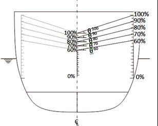
This approach is seen illustrated in Fig. 3.
V-line roll and heave allowances varying with the
probability of the water level exceeding the line. This
approach allows the simple selection of V-line and red
risk criteria based on an acceptable probability of
exceedence.
Throughout this paper the measure ‘percentile water
height’ is used in place of a probability of exceedence
in order to align with convention. For example the 95th
percentile water line refers to a line with a 5%
probability of exceedence; i.e. a line that provides
coverage of 95% of recorded water heights.
In order to calculate the V-line allowances, water
height sensors were placed on the bounding bulkheads
of the damage regions arising from each of the
Figure 3 –Lines of probability of exceedence of water
damage scenarios. Sensors were placed at the
heights for the calculation of V-line criteria
centreline and at outboard points within the damaged
compartments. Where subdivision was present in the The resulting percentile relative water height
deck plane, multiple sensors were required in order to allowances are referred to as heave and roll
provide coverage of the full range of water heights. allowances in line with the terminology of the V-line
An example of water height sensor placement is seen standard, however in reality these terms are not
in Fig. 2. conceptually accurate. By combining the centreline
and outboard water height probabilities, the vessel
heave allowance directly impacts the roll allowance
Port Starboard calculated; for example maximum roll motions may
predominantly occur as the vessel is at the peak of its
heave oscillations, meaning the outboard 95th
percentile water height may only be fractionally
higher than the centreline point, despite the vessel
rolling significantly. This results in a ‘roll’ allowance
Figure 2 - Placement of water height sensors of only a few degrees despite the vessel rolling
© Marine Technology Centre, UTM 61The 14th International Ship Stability Workshop (ISSW), 29 September-1 October 2014, Kuala Lumpur, Malaysia
significantly more than this. Fundamentally, the Table 4 summarises the worst case heave and roll
approach adopted succeeds in combining both roll and allowance results of the OPV, MCMV and the
heave motions to give a probabilistic V-line which Destroyer (DEST) in sea state 4 conditions following
reflects the actual waterline as opposed to modelling it symmetric and asymmetric damage.
through independent criteria where the worst case roll
Table 4 Summary of combatant heave and roll allowances
and worst case heave are assumed to occur
(angle from upright) in a maximum sea state 4
simultaneously.
In order to further understand the relationship 95% V-line 95% Vessel
Ship/ Heading criteria motions
between vessel motion and local water height, global Damage
allowance (deg) Heave Roll Heave Roll
vessel motions, taken from vessel earth axis motions, (m) (deg) (m) (deg)
were calculated, highlighting where the vessel was OPV H Sym 178 0.70 0.18 0.50 0.32
OPV R Sym 090 0.40 10.20 1.10 12.28
contouring the waves in heave and roll or where
OPV H Asym 315 0.98 0.70 0.66 19.72
waves were affecting the local water height at each
OPV R Asym 090 0.55 5.70 1.13 25.10
bulkhead.
MCMV H Sym 002 0.74 0.15 0.64 0.29
5. Results MCMV R Sym 090 0.40 7.02 1.12 8.55
MCMV H Asym 002 0.84 2.62 0.73 20.58
Tables are presented giving a summary of the worst
MCMV R Asym 090 0.44 5.77 1.10 23.10
case 95th percentile heave and roll allowances for the
DEST H Sym 002 1.00 0.08 0.50 0.20
combatants and non-combatant vessels. The results for
DEST R Sym 090 0.28 3.54 1.09 4.07
the maximum sea state 4 and a maximum sea state 6 Asym 002 0.77 0.00 0.39 7.52
DEST H
are presented. In conjunction with these results Asym 090 0.30 2.69 1.06 10.53
DEST R
statistical measures of the vessel roll and heave
motions are also presented.
In sea state 4 conditions the heave allowances
In the tables of results the vessel designators are
can be seen to be below both the original Sarchin and
followed by either a H, corresponding to the vessel
Goldberg dynamic heave allowance of 1.22m and the
heave allowance, or by an R, corresponding to the
larger DefStan 02-900 allowance of 1.5m. The worst
vessel roll allowance.
case 95th percentile heave allowances are seen to
Table 3 outlines the static damaged list angles of
occur predominantly in following sea and head sea
all vessels following damage allowing an
conditions, as expected, where pitching motions are at
understanding of the final Red Risk and V-line levels.
their greatest, contributing to waterline height on the
Table 3 Damaged list angles
bulkhead centre point.
Symmetric damage Asymmetric damage
Sea State In all cases the worst case roll allowance is also
list angle (deg) list angle (deg)
OPV 0 17.4 substantially below the 15° defined in DefStan
MCMV 0 17.3 02-900. Even where large vessel roll motions are seen,
Destroyer 0 7.2 the corresponding roll allowance is seen to be small,
Small Auxiliary 0 18.1 suggesting that the smaller vessels are contouring the
Large Auxiliary 0 17.9
beam sea waves. It is important to note that where
Tanker 0 6.3
high roll allowances are seen following symmetric
5.1. Combatant Results damage, these are unlikely to drive final V-line angle
© Marine Technology Centre, UTM 62The 14th International Ship Stability Workshop (ISSW), 29 September-1 October 2014, Kuala Lumpur, Malaysia
as following symmetrical damage the mean list angle The MCMV and Destroyer are both seen to
is negligible. This is illustrated in Fig 4: experience large vessel roll angles, indicated by the
95th percentile vessel motion statistics. Despite this,
V Line roll allowances are again seen to be predominantly
low.
Red Risk Line
Following symmetric damage to the MCMV a
15o
roll allowance of 17.6° was seen. Whilst this is outside
Damage Waterline
1.5m the roll allowance found in DefStan 02-900, the
DefStan allowance is applied to the worst case
Intact Waterline
damaged waterline, i.e asymmetric heel up to 20
degrees. Therefore, a DefStan V-line angle would be
35° under current rules compared to 17.6° using the
L
C
results of the analysis, despite a larger roll allowance
Figure 4 – V-line and Red Risk line composition being used.
Table 5 presents the results of the three In all cases heave allowances were seen to fall
combatants following damage in a maximum sea state below current naval V-line standards despite large
6. Due to the significant damage cases (worst cases heave motions being seen. Once again worst case
under DefStan 02-900) the OPV was found to capsize heave allowances were calculated in head and
in a number of heading in these large sea state 6 following seas.
waves and as a consequence results are not available 5.2. Non-combatant Results
for these runs.
Table 5 Summary of Combatant heave and roll allowances The non-combatants examined were all large
in a maximum sea state 6 vessels with greater freeboard and reserves of
95% V-line 95% Vessel buoyancy than their combatant counterparts. In
Ship/ Heading criteria motions addition the relative wave size of a sea state 6 when
Damage
allowance (deg) Heave Roll Heave Roll
(m) (deg) (m) (deg) compared to vessel size is less onerous than those seen
OPV H Sym Vessel capsized – no results available in the smaller combatant vessels.
OPV R Sym Vessel capsized – no results available
Table 6 outlines the worst case roll and heave
OPV H Asym Vessel capsized – no results available
allowance for the three non-combatants in sea state 4
OPV R Asym Vessel capsized – no results available
Sym 045 1.16 8.89 2.40 16.49
conditions.
MCMV H
MCMV R Sym 270 0.40 17.58 2.39 19.03
MCMV H Asym 135 1.45 7.44 2.39 25.43
MCMV R Asym 270 0.56 11.73 2.42 30.92
DEST H Sym 002 1.32 0.24 1.70 0.92
DEST R Sym 225 0.57 13.38 1.76 12.15
DEST H Asym 178 1.27 0.00 1.65 8.88
DEST R Asym 090 0.58 8.48 2.63 16.98
© Marine Technology Centre, UTM 63The 14th International Ship Stability Workshop (ISSW), 29 September-1 October 2014, Kuala Lumpur, Malaysia
Table 6 Summary of non-combatant heave and roll Table 7 outlines the worst case roll and heave
allowances in a maximum sea state 4 allowance for the three non-combatants in sea state 6
conditions. The results presented in table 7 (*
95% V-line 95% Vessel
Ship/ Heading criteria motions correspond to a mean sea state 6).
Damage
allowance (deg) Heave Roll Heave Roll
(m) (deg) (m) (deg) Table 7 Summary of non-combatant heave and roll
Small Aux H Sym 002 1.06 0.05 0.43 0.53
allowances in a maximum sea state 6
Small Aux R Sym 090 0.34 2.66 1.00 3.59 95% V-line 95% Vessel
Small Aux H Asym 270 1.83 0.00 0.57 22.52 Ship/ Heading criteria motions
Damage
allowance (deg) Heave Roll Heave Roll
Small Aux R Asym 090 1.06 2.63 1.15 24.63
(m) (deg) (m) (deg)
Large Aux H Sym 002 1.05 0.04 0.32 0.47 Small Aux H Sym 002 1.93 0.14 1.54 1.01
Large Aux R Sym 090 0.30 1.03 0.87 1.71 Small Aux R Sym 090 0.64 8.79 2.78 10.08
Large Aux H Asym 178 1.66 0.00 0.31 15.76 Small Aux H Asym 270 2.66 0.00 2.08 24.37
Large Aux R Asym 090 0.95 0.86 0.93 15.45 Small Aux R Asym 045 1.53 2.33 1.93 22.48
Tanker H Sym 045 1.30 0.08 0.69 1.18 Large Aux H Sym 135 1.75 3.79 1.44 2.75
Tanker R Sym 090 0.61 2.31 0.79 3.24 Large Aux R Sym 225 1.09 6.38 1.32 2.29
Tanker H Asym 090 1.51 0.00 0.92 7.15 Large Aux H Asym* 178 2.59 0.00 0.77 17.90
Tanker R Asym 270 0.67 3.65 0.62 13.89 Large Aux R Asym* 090 1.17 3.29 2.09 18.13
Tanker H Sym 002 3.48 0.03 0.26 1.59
In all cases the DefStan 02-900 roll allowance Tanker R Sym 225 2.15 8.45 1.61 21.37
was not exceeded by the simulation results; this is Tanker H Asym 002 2.48 0.00 1.37 6.10
despite relatively large roll motions being seen in the Tanker R Asym 270 1.05 6.45 1.93 19.40
case of the small auxiliary (24.63°). Worst case roll
allowances were seen to occur in beam sea conditions In sea state 6 conditions roll allowances are still
and were seen following symmetric damage, with the seen to fall substantially below the current DefStan
exception of the tanker whose worst case roll requirement, suggesting that for these larger vessels
allowance was seen following asymmetric damage the criteria could potentially be relaxed from the 15
(13.89 degrees). degree roll allowance.
The DefStan heave allowance was seen to be The worst case heave V-line allowances are seen
exceeded by all three vessels, the worst being the to be very high when compared to the current 1.5m
small auxiliary with 0.33 metre exceedence following standard. In most cases these high allowances
asymmetric damage. In these cases vessel global correspond to relatively low global vessel heave
heave motions were low, suggesting that the vessel motions, aligning with the results seen in the sea state
did not react in heave to the incident wave, resulting 4 analysis. The 95th percentile heave allowance for the
in the centreline water height being water inflow large auxiliary was found to exceed current standards
through the damage. These results suggest that for a in all conditions greater than a sea state 4 with a 25%
larger vessel, reacting more slowly to incoming probability of the 1.5m allowance being exceeded
waves, the current naval standards do not provide seen in a sea state 4. In the sea state 6 the internal
coverage of likely centreline water levels. water level heave allowance was between 1 and 2m
above the current V-line standard.
© Marine Technology Centre, UTM 64The 14th International Ship Stability Workshop (ISSW), 29 September-1 October 2014, Kuala Lumpur, Malaysia
6. Conclusions additional level of conservatism. All the
vessel-damage scenario combinations examined have
It has been shown that following this
a 95th percentile probabilistic roll allowance in a sea
methodology and using a suitable time-domain code
state 4 of less than 11°, showing the current criteria is
that the Red Risk and V-lines criteria can be evaluated
suitable for sea state 4 for modern vessels.
for different sized vessels.
The heave allowance is seen to be significantly
Current Def Stan 02-900 V-line criteria are based
more sensitive to vessel size than roll allowance. The
upon the original Sarchin and Goldberg work of 1962
current heave allowance is not exceeded by any of the
which was based around the seakeeping characteristics
smaller combatant vessels in a sea state 4, with the
of frigate sized vessels of that time. By examining
maximum 95th percentile heave allowance of 1.0m in
water heights at the bounding bulkheads of damage
the case of the destroyer.
cases across a range of modern indicative vessel
designs, the suitability of these historic criteria has In a maximum sea state 6 the highest combatant
been assessed. 95th percentile heave allowance was seen to be 1.45m.
However in the case of the larger non-combatant ships
The new approach of forming a probabilistic
examined, these heave allowances do not appear to be
water height line, which covers probability percentiles
as suitable. The larger ships are seen to experience
of bulkhead submergence, leads to heave and roll
greater bulkhead water heights, not as a result of the
being considered together to form allowances that
vessel global vertical motions, but instead as a result of
represent the actual percentage of time that points on
local water height as the vessel experiences small
the bounding bulkhead spend submerged. This is in
vertical motions and large flows in and out of the
contrast to current criteria which are based on the
damage region. A heave allowance of 1.9m is required
individual consideration of maximum roll angles and
in order to ensure a 95% probability of compliance in a
maximum heave motions, and do not account for the
sea state 4 for the vessels and damage cases examined.
fact that these two occurrences are unlikely to manifest
This allowance increases to 3.5m in a sea state 6.
themselves at the same time.
It appears evident that applying the current V-line
It is clear that the vessels considered in this report
standard roll allowance of 15° and heave to modern
must be assessed as two groups to truly understand the
combatant designs is conservative up to a sea state 6.
applicability of the existing standards; namely smaller
Similarly the current heave allowance of 1.5m also
combatants and larger non-combatants.
appears conservative when applied to modern
Unsurprisingly, vessel size is seen to significantly
combatants up to the sea state 6 conditions examined.
affect the probabilistic heave and roll allowances of a
The roll allowance standard for large non-combatants
vessel as a direct result of the different seakeeping
is seen to be very conservative and could be reduced
behavior the vessels exhibit in larger sea states.
significantly whilst still maintaining a 95% probability
The current naval standards, based around World of compliance in a sea state 6, however, the
War 2 frigates, appear conservative when applied to a non-combatant heave allowance may require a
modern day destroyer design. Maximum roll significant increase over current standards.
allowance angles are predominantly seen following
symmetric damage cases and the application of these
allowances to an asymmetric list angle results in an
© Marine Technology Centre, UTM 65The 14th International Ship Stability Workshop (ISSW), 29 September-1 October 2014, Kuala Lumpur, Malaysia
Acknowledgments MARIN, FREDYN Flooding Module – version 3.2.0.0
User Manual, March 2010
The authors would like to gratefully
acknowledge the permission granted by QinetiQ and
United Kingdom Defence Standard 02-900, General
CRN Navies for allowing the publication of the
Naval Standard Part 1: Ship Safety & Environmental
findings from the investigation.
Protection, Issue 1, Aug 2013
References
United Kingdom Maritime Acquisition Publication No
Sarchin, T.H. and Goldberg, L.L., Stability and
01-024, Stability of Surface Ships Part 1 Conventional
Buoyancy Criteria for US Naval Surface Ships,
Ships, Issue 4, October 2010
Transactions SNAME, 1962
Dawson, N.A. Work Package 2 – Damage Sensitivity
De Kat, J.O., Peters A.J. Damage Stability of Frigate
Analysis QINETIQ/MS/MAR/CR1303691, September
Sized Ships, International Maritime Association of the
2013.
Mediterranean Conference, Crete, 2002
Andrew J. Peters QinetiQ, Haslar Marine Technology
MARIN, FREDYN – A computer program for the
Park, (UK), An Investigation into the V-Line Criteria for
simulation of a steered ship in extreme seas and wind,
Naval Vessels, 2004
User’s Manual Version 10.3, Part I – Intact Hull, May
2011
Hasselmann K. et al., Measurements of wind-wave
growth and swell decay during the Joint North Sea Wave
Project (JONSWAP). Ergnzungsheft zur Deutschen
Hydrographischen Zeitschrift ReiheA(8) (Nr. 12): 95,
1973
Ewing J, Some results from the Joint North Sea Wave
Project of interest to engineers, First international
symposium on the dynamics of marine vehicles in
waves, IMechE, 1974.
© Copyright QinetiQ Ltd 2014
© Marine Technology Centre, UTM 66You can also read