MarkVCID Spectral Domain Optical Coherence Tomography Angiography (OCTA) Imaging Acquisition Instructions
←
→
Page content transcription
If your browser does not render page correctly, please read the page content below
MarkVCID Spectral Domain Optical
Coherence Tomography Angiography
(OCTA) Imaging Acquisition Instructions
Version 9, June 16, 2020
MarkVCID Consortium

Developed in collaboration with the Keck Medicine of University of California Roski
Eye Institute (PI Amir Kashani, MD, PhD) and the MarkVCID Coordinating Center.

The MarkVCID Consortium is funded by the National Institutes of Health through
the National Institute of Neurological Disorders and Stroke and National Institute
on Aging (Cooperative Agreement U24NS100591).

                                             MarkVCID OCTA Acquisition Instructions | v9 updated 06.16.20 | 1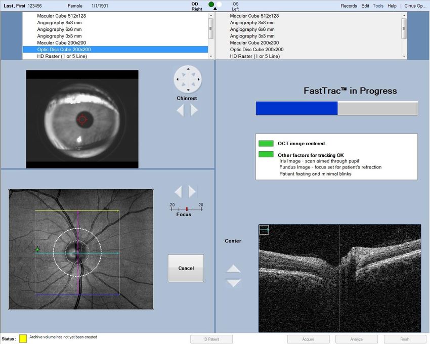
MarkVCID Spectral Domain Optical Coherence Tomography Angiography (OCTA)
                 Imaging Acquisition Instructions | v9 6/16/20

Note: The following is a scanning protocol intended for obtaining OCTA images
on research subjects.

Table of Contents
I.    Obtaining OCTA Images ............................................................................. 3
II.     Export Deidentified Data ........................................................................... 16
III.    Export Bitmap Images ............................................................................... 19
IV.     Change Date Back to Real Date ............................................................... 22
V.      VSD Analysis ............................................................................................ 22
VI.    Data Management                                                                                           28
VII.   Test-Retest Acquisition ................................................................................. 30
VIII. Cleaning the Eyepiece Lens                                                                                30

                                                    MarkVCID OCTA Acquisition Instructions | v9 updated 06.16.20 | 2
I.          Obtaining OCTA Images

       1. Turn on the device (Cirrus 5000 SD-OCTA) by pressing the power button.

       2. The system will start up and the program should open on its own. However, if it
          does not, the program may be located on the desktop as icon “Cirrus HD-OCT.”

       3. After the program opens and the “Start Up Check” has finished, click “Continue”.

       4. It is essential that the date of acquisition be anonymized on the device. In order
          to do this, the date of the computer operating system must be temporarily
          changed during the scan acquisition and then restored to its correct value
          immediately after acquisition.

       5.    In order to change the date of the operating system, press the “ALT” and “TAB”
            key at the same time to navigate to the Windows operating system desktop.

       6. In the bottom right hand corner of the Windows desktop, you will see the date
          and time (Figure 1). Right click on the data and time display and select “Adjust
          date/time” (Figure 2).

     Figure 1: Screenshot of desktop. Date and time is highlighted with red-dotted square.

                                            MarkVCID OCTA Acquisition Instructions | v9 updated 06.16.20 | 3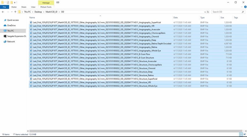
Figure 2: Screenshot of “Adjust date/time.” “Adjust date/time” is highlighted with red-dotted
circle

  7. To change the date, you must deselect “Set time automatically” (Figure 3).

Figure 3: Screenshot of “Date & Time Window” to turn off automatic time set highlighted
with red-dotted square

  8. Once it is turned off, you will notice that under “Set the date and time manually”
     there is a button labeled “Change” (Figure 4). Click on “Change.”

                                        MarkVCID OCTA Acquisition Instructions | v9 updated 06.16.20 | 4
Figure 4: Screenshot of “Change” to reset date and time.

  9. A dialog box pops up to manually change the date and time (Figure 5).
     Depending on which visit is being conducted, change the date to the following
     format “1/(study visit #)/(current year +1).” Examples are provided below:

      Visit 1: Set date to “1/1/(current year +1)”
      (i.e. if the year is 2020 then 1/1/2021)

      Visit 2: (for different day test or retest) “1/2/(current year +1)”
      (i.e. if the year is 2020 then 1/2/2021)

      Visit 3: (annual visit) “1/3/(current year +1)”
      For a subject that was not included in the test-retest cohort, their annual
      visit would still be “1/3/(current year +1).”
      (i.e. if the year is still 2020 then 1/3/2021. If the year is 2021 then
      1/3/2022)

                                         MarkVCID OCTA Acquisition Instructions | v9 updated 06.16.20 | 5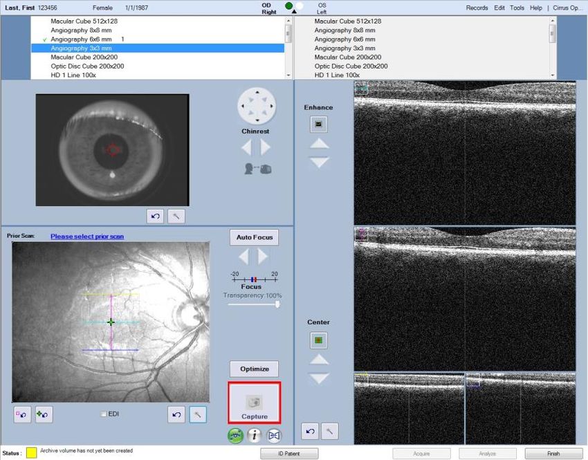
Figure 5: Screenshot of changing date
Date and time is highlighted with red-dotted circle

  10. After entering the new date, click “Change” and return back to the “Cirrus HD-
      OCT” program. The date/time display in the lower right-hand corner of the
      Windows desktop should now show the new date that was entered.

  11. For User Login, choose “Cirrus Operator” from the dropdown menu, type in the
      password, then click “Ok”.

  12. If registering a NEW patient, enter the patient information under the “Add New
      Patient” tab. Enter the MarkVCID subject ID number that was generated in the
      Subject Registration page of the MarkVCID web portal. If the subject does not
      have a MarkVCID ID, please register the subject before the session so you may
      input the ID at this step. Please check with your study coordinator to ensure there
      is no subject ID, before registering the subject.

      If entering data on a returning patient, look up the patient by last name or ID on
      the “Find Existing” tab. After entering the information, click “Save” and then the
      “Acquire” button at the bottom-right side of the screen.

  13. This protocol will use only one angiography option and one OCT option from the
     list.
           a. Perform “Angiography 3x3 mm” scan first. This is a 3x3 mm scan
              centered on the foveal avascular zone (the default will center the square
              over the foveal avascular zone when you click on the Angiography 3x3
              mm option).
                   ➢ Prior to acquisition, make sure the foveal dip is centered for the
                       two scans on the top-right corner of the screen (Figure 6).
                   ➢ Scans should be taken in quadruplicate (4 repeated scans). Have
                       the subject blink three times before the next acquisition.
                   ➢ Refer to Figures 6-9 for screenshots of the device for this scan
                       sequence.
           b. The “Eye Tracking” feature must be active. This allows the device to
              track the eye movements of the patient in real time and avoid movement
              artifacts. If the outline of the box labeled “Capture” is green, the tracking

                                        MarkVCID OCTA Acquisition Instructions | v9 updated 06.16.20 | 6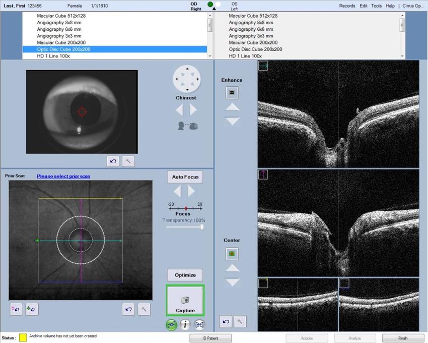
feature is active. If it is red, the image cannot be tracked for one of
several reasons.
    ➢ In Figure 6, notice that the outline box around “Capture” button is
        green. This means the device is able to track.
    ➢ In Figure 7, notice the outline box around the “Capture” button is
        red. This means the device is not able to track.
            • If the “Capture” button is red, move the red circle with
                cross-hairs in the top-left panel to the center of the pupil by
                clicking on the center of the pupil.
            • Click on autofocus or manually focus using the arrows
                located underneath autofocus (Figure 7).
            • Make sure to ask the subject to blink their eyes a few
                times.
            • If the “Capture” button is still outlined in red you may apply
                1 drop of a commercially available artificial tear (RefreshTM,
                GentealTM, SystaneTM, or OptiveTM) to each eye and try the
                scan again after 1 minute.
    ➢ In Figure 8, you will see the screen after you click “Capture.”

                           MarkVCID OCTA Acquisition Instructions | v9 updated 06.16.20 | 7
14. After a single acquisition is complete, you will see four images (Figure 9): the
      front of the eye (pupil) in the upper-left, the OCT in the upper-right, the en face
      image on the bottom-left, and the angiogram on the bottom-right. Take note of
      the “Signal Strength” in the top-middle.
          a. The “Signal Strength” should be 8 or higher.
          b. The circle next to “tracked during scan” should be green.
          c. Please check the en face image in the bottom-left and angiogram in the
               bottom-right for any shadows that appear to obscure the underlying
               image or any dark regions that suggest an artifact such as movement or
               floater.
          d. If the scan appears poor (movement, floater, etc) click “Try Again” and try
               to capture the image again. If the image appears good, click “Save” and
               continue to the next scan.

  15. Repeat step 6 and 7 a total of four times to obtain four repeated scans of the
      same region.

Figure 6: Screenshot of “Angiography 3x3mm” immediately prior to acquisition
Note:
The box around the “Capture” square should be green for successful acquisition.
The foveal dip should be centered on both panels in the right-middle panels of the screen.

                                       MarkVCID OCTA Acquisition Instructions | v9 updated 06.16.20 | 8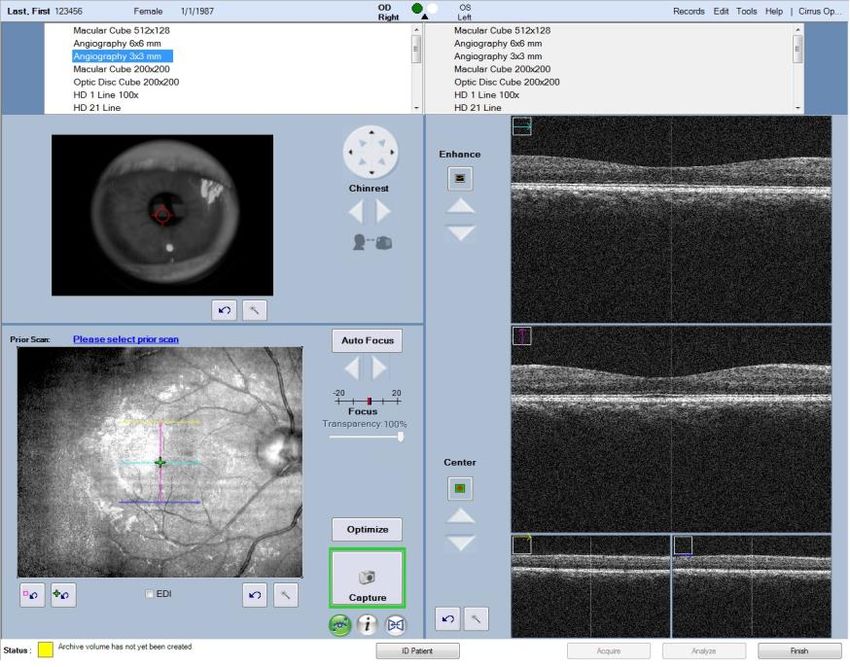
Figure 7: Screenshot of “Angiography 3x3mm” immediately prior to acquisition with
red “Capture” button. In this case, the device cannot track because the OCT image is
outside the acquisition window in the right panels. Autofocus option (red dotted box)

Figure 8: Screenshot of “Angiography 3x3mm” scan during scan acquisition

                                      MarkVCID OCTA Acquisition Instructions | v9 updated 06.16.20 | 9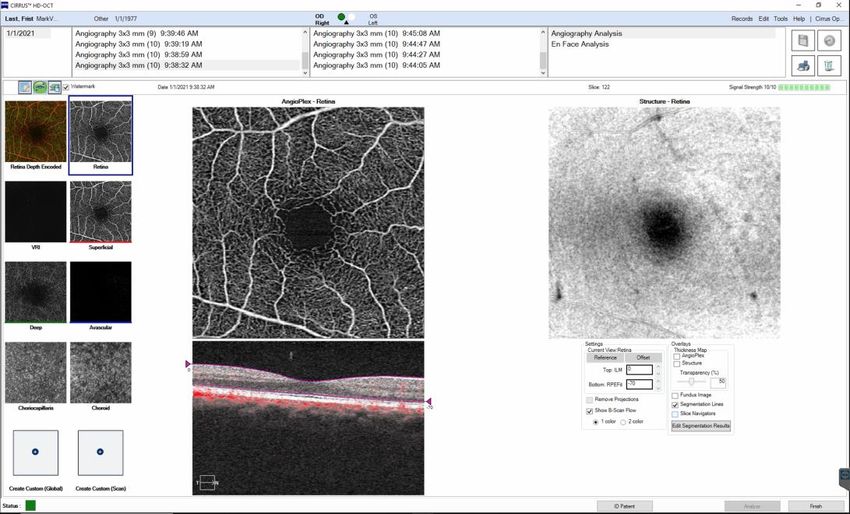
Figure 9: Screenshot of the “Angiography 3x3mm” scan after acquisition
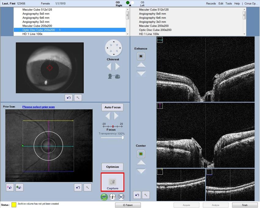
16. Next perform “Optic Disc Cube 200x200” scan. Click on “Optic Disc Cube
200x200.” The default setting will move the fixation point so that the optic disc is
centered on the scan pattern.
➢ A box will appear in the lower-left panel with cross-hairs and two
concentric circles in the middle.
➢ Make sure the inner most circle is centered around the optic disc.
The circle should be centered evenly on the disc (Figure 10).
➢ Scans should be taken in quadruplicate (4 scans). Have the
subject blink three times before the next acquisition.
➢ Please note, the acquisition time for the Optic disc cube is much
faster than that for the angiography scan.
➢ Refer to Figures 10-13 for screenshot of the device for this scan
sequence.
As with the angiography scan, the “Eye Tracking” feature must be active. This
allows the device to track the eye movements of the patient in real time and
avoid movement artifacts. If the outline of the box labeled “Capture” is green, the
tracking feature is active. If it is red, the image cannot be tracked for one of
several reasons.
➢ In Figure 10, you will notice that the outline box around capture is
green. This means the device is able to track.
➢ In Figure 11, you will notice the outline box around the capture is
red. This means the device is not able to track.
• If the “Capture” box is red, move the red circle with cross-
hairs in the top-left panel to the center of the pupil by
clicking on the center of the pupil.
• Make sure to ask the subject to blink their eyes a few
times.
• Click on autofocus or manually focus using the arrows
located underneath autofocus (Figure 11).
• If the “Capture box” is still outlined in red you may apply 1
drop of a commercially available artificial tear (RefreshTM,
GentealTM, SystaneTM, or OptiveTM) to each eye and try the
scan again after 1 minute.
MarkVCID OCTA Acquisition Instructions | v9 updated 06.16.20 | 10➢ In Figure 12, you will see the screen after you click “Capture.”
17. After acquisition is complete, you will see five images: the front of the eye in the
upper-left, the en face image on the bottom-left, and 3 OCT sections on the right
side (Figure 13). Take note of the “Signal Strength” in the top middle.
a. The “Signal Strength” should be 8 or higher.
b. The circle next to “tracked during scan” will be green.
c. Please check the en face image in the bottom-left for any shadows that
appear to obscure the underlying image or any dark regions that suggest
an artifact that disrupts the OCT scans.
d. If the scan quality appears poor, click “Try Again” and try to capture the
image again. If the image appears okay, click “Save” and continue to the
next scan.
18. Repeat steps 9 and 10 a total of four times to obtain four repeated scans of the
same region.
Figure 10: Screenshot of “Optic Disc Cube 200x200” immediately prior to acquisition
Note:
The box around the “Capture” button should be green for successful acquisition.
The optic disc should be evenly centered within the smallest white circle in the lower-left
panel.
MarkVCID OCTA Acquisition Instructions | v9 updated 06.16.20 | 11Figure 11: Screenshot of “Optic Disc Cube 200x200” immediately prior to acquisition
with red “Capture” box. In this case, the red circle with cross-hairs should be re-
centered in the top-left panel and the OCT image in the right panels should be kept
completely inside the acquisition window. Autofocus option (red dotted box)
Figure 12: Screenshot of “Optic Disc Cube 200x200” scan during acquisition
MarkVCID OCTA Acquisition Instructions | v9 updated 06.16.20 | 12Figure 13: Screenshot of the “Optic Disc Cube 200x200” scan after acquisition
19. After you save the last image, click “Finish” and review the images by clicking on
the patients name in the “View Today’s Patient” tab or searching for the patient in
“Find Existing Patient” tab and clicking “Analyze” at the bottom right-hand corner
of the screen (Figure 14).
a. Click on the "Angiography 3x3mm” and click “Angiography Analysis” on
the upper right-hand side (Figure 15).
b. The image will pop up in the center and the structural image will be on the
right. Check the structural image for any artifacts that may results in any
of the below artifacts (Figure 16-20).
Figure 14: Screenshot of patient selection page image review
MarkVCID OCTA Acquisition Instructions | v9 updated 06.16.20 | 13Figure 15: Screenshot of “Angiography Analysis” to review images.
20. Examples of good versus poor images are below for Angiography 3x3mm (Figure
16-20).
Figure 16: Examples of a “good” OCTA scan. The foveal avascular zone (dark region
in the center) is well-centered. There are no bright or dark lines across either image.
The larger vessels in the angiogram (left image) are not broken or discontinuous.
Figure 17: Examples of a “good” OCTA scan in subject with smaller foveal avascular
zone. This subject has a relatively small foveal avascular zone but it is well centered
in the image. There are no dark or bright lines across either image. There are no
breaks or discontinuity in the larger vessels in the angiogram (left).
MarkVCID OCTA Acquisition Instructions | v9 updated 06.16.20 | 14Figure 18: Examples of a “poor” OCTA scan due to floaters that cause shadows in the
angiogram (left) and the structural image (right)
Figure 19: Examples of a “poor” OCTA scan due to decentered fovea
Figure 20: Examples of a “poor” OCTA scan due to motion artifacts (dark and bright
bands across the structural image in the right panel). Also note the broken vessels
(yellow arrows) in the angiogram on the left.
MarkVCID OCTA Acquisition Instructions | v9 updated 06.16.20 | 15II. Export Deidentified Data
1. In the software, click on “Records” in the top right-hand corner (Figure 21).
Figure 21. Screenshot of records to export exams
2. Choose “Export Exams…” and a dialog box comes up (Figure 22).
Figure 22: Screenshot of Export Options for deidentified export
MarkVCID OCTA Acquisition Instructions | v9 updated 06.16.20 | 163. Choose the path to export to and uncheck “Export in Zip Format”.
4. There should be a checkmark next to “Omit Patient Identifiers” and “Omit Patient
Name, day and month of birth” should be chosen.
5. You can search by last name, Patient ID (i.e. MarkVCID subject ID), or choose
“All”, “Last 90 Days”, “Last 60 Days”, “Last 30 Days”, “Last 7 Days” or an interval.
It would be best to export data patient-by-patient so they can be easily identified.
6. After choosing the first patient, click “Search”.
7. The names and ID of the patient appears.
Figure 23: Screenshot of patient selection
8. Click on the patient you would like to export (Figure 23).
9. Click on the “Exam Export” tab and to choose which exam(s) to export
(Figure 24). All exams should be exported.
MarkVCID OCTA Acquisition Instructions | v9 updated 06.16.20 | 17Figure 24: Screenshot of the exam selection page
10. Then click “Export.”
11. After the export is completed, proceed to export the next patient by following the
instructions above.
MarkVCID OCTA Acquisition Instructions | v9 updated 06.16.20 | 18III. Export Bitmap Images
1. Search for the patient you are looking for in the same manner as described
above.
2. Click on the name of the patient and click on “Analyze” in the bottom-right
(Figure 25)
Figure 25: Screenshot of patient selection page for bitmap export
3. Click on “Angiography 3x3mm” then click on “Angiography Analysis” in the top-
right (Figure 26). Before choosing one of the “Angiography 3x3mm” images to
export, review all four images acquired per eye and choose the one you think
would be the best quality for each eye. Refer to the examples in Figure 16-20 to
assist in your decision.
Figure 26: Screenshot of slice navigators (blue and purple cross hairs in the center
panels)
MarkVCID OCTA Acquisition Instructions | v9 updated 06.16.20 | 194. The blue horizontal line and the purple vertical lines are slice navigators and
should not be in the image before you export. Before exporting the bitmap files,
you need to uncheck “Slice Navigators” in the bottom-right panel above where it
says “Edit Segmentation Results” (Figure 27).
Figure 27: Screenshot of unchecked slice navigators (red dotted circle) option
resulting in removal of the cross hairs shown in Figure 19.
5. On the left-side of the screen you will see the different layers displayed in 8-10
small panels.
6. Above the small panels there is a very small watermark checkbox option that you
want to make sure is not checked (Figure 28).
Figure 28: Screenshot of unchecked “watermark” dialogue box (red dotted circle)
7. Immediately to the left of the watermark is an icon that will export all images.
8. By clicking on that option, a dialog box will pop up in which you can choose
where to save the images. Create a folder named with the MarkVCID Subject ID.
MarkVCID OCTA Acquisition Instructions | v9 updated 06.16.20 | 20In that folder, create a folder labeled “OD” for the right eye image and another
named “OS” for the left eye images (Figure 29).
Figure 29: Screenshot of the image save location dialogue box (red dotted circle).
9. After you click “OK”, all images will be exported (Figure 30).
Figure 30: Screenshot of bitmap export finish step
10. After exporting the right eye images, proceed to exporting the left eye images
following the steps above, except putting the images in the “OS” folder.
MarkVCID OCTA Acquisition Instructions | v9 updated 06.16.20 | 21IV. Change Date Back to Real Date
1. After the acquisition and export process is over, you must change the date of the
Windows operating system back to the current date.
2. The steps that follow are essentially the same as stated above.
3. In order to change the date of the operating system, press the “ALT” and “TAB”
key at the same time to navigate to the Windows operating system desktop.
4. In the bottom right hand corner of the Windows desktop, you will see the date
and time (Figure 1). Right click on the data and time display and select “Adjust
date/time” (Figure 2).
5. Since the “Set date automatically” was turned off, if you just select it, the date
should return to the current date (Figure 3).
6. After you have turned the “Set date automatically” on, you can close the dialog
box.
7. Double check the date and time at the bottom right hand corner to ensure
that it was returned to the correct date.
V. VSD Analysis
1. Open the folder labeled with the MarkVCID Subject ID where all the image files
are saved from the previous section in “OD” and “OS” subfolders. “OD” and “OS”
images will be run separately.
2. Delete all scans in the folder that do not end in “Angiography_Superficial” and
“Structure_Superficial” (Figure 31). Only two scans will remain (Figure 32).
3. Right click on the remaining files and choose “rename”. Delete the name of the
patient that appears in the beginning of the file title.
4. Create a new folder and move the file that ends in “Angiography_Superficial” to
the new folder. Make sure to choose the “Angiography_Superficial” and not
“Structure_Superficial” (Figure 31).
5. Place the “Angiography_Superficial” image in a separate folder (Figure 32).
MarkVCID OCTA Acquisition Instructions | v9 updated 06.16.20 | 22Figure 31: Screenshot of Selection of files highlighted to be deleted
Figure 32: Screenshot of the removal of the subject name from files
MarkVCID OCTA Acquisition Instructions | v9 updated 06.16.20 | 236. Before the first time you run the VSD Analysis executable file, you must first run
the “MyAppInstaller_web.exe” (Figure 33). This only needs to be done once
before quantification. Click on next to install.
Figure 33: Screenshot of the “MyAppInstaller” program to install
7. After “MyAppInstaller_web.exe” is installed successfully (Figure 34), click finish.
Figure 34: Screenshot of the “MyAppInstaller” installation complete
8. Double click on “OMAG_VSD_3x3” executable file to perform the VSD analysis.
9. A dialog box will pop up where you will load the image (Figure 35). This may
take a few minutes.
MarkVCID OCTA Acquisition Instructions | v9 updated 06.16.20 | 24Figure 35: Screenshot of the “OMAG_VSD_3x3” program to load image for analysis
10. Click on load image and select the image you want to analyze (Figure 36). Only
“Angiography_Superficial” images will be analyzed.
Figure 36: Screenshot of the “OMAG_VSD_3x3” program to load image for analysis
11. After the image is loaded (Figure 37), two cross-hair lines appear with the center
being the pointer.
MarkVCID OCTA Acquisition Instructions | v9 updated 06.16.20 | 25Figure 37: Screenshot of Loaded Image with cross hairs or hash lines
12. Using the cross hairs, click three times in the center of the fovea and the analysis
will automatically run (Figure 38). It is important to avoid clicking on any region
with white pixels during this step. Only click in three regions within the center of
the fovea where there are no white pixels. In rare cases there may be no such
region or it may be very small. In such a case please contact the lead MarkVCID
site for guidance (located at the end of the document).
Figure 38: Screenshot of threshold selection after clicking on fovea three times with
cross-hairs
13. After the image is done running, there will be a number above the colored image
on the right that says “VSD=0.XXXXXX” (Figure 39). Record that number as the
output of the analysis program into an excel workbook to keep track of the
analysis results.
MarkVCID OCTA Acquisition Instructions | v9 updated 06.16.20 | 26Figure 39: Screenshot at end of VSD analysis
14. If you look at the folder where the original image was stored, you will see there
are four files saved (Figure 40) as follows:
a. Three images files with added identifiers at the end of the file name.
i. “…Original Image”
ii. “…Skeleton Image”
iii. “…Vessel Skeleton Density Map”
b. One new excel file that ends in “….data.xlsx”
If you were unable to copy the number for VSD, you can locate it in the Excel file
labeled data.
Figure 40: Screenshot of saved files after VSD analysis is complete
MarkVCID OCTA Acquisition Instructions | v9 updated 06.16.20 | 27VI. Data Management
In order for the MarkVCID data management system to identify the OCTA data,
the scan session should be registered on the MarkVCID website. In addition, the
data should be organized in a standard structure and transmitted to the data
management team using the Globus data transfer service. Please see the
documents available here that describe the registration of the subjects (if they
have not yet been registered by your site), the registration of the scan sessions,
and the transfer of the data. The documents containing information relevant to
OCTA data are under the Imaging Standard Operating Procedures tab in the
“Imaging Data Registration SOP” and “Globus Installation and File Transfer”
documents. You may also want to download the “MarkVCID Imaging Doc ID Log
Template”, which can be used to record the scan session IDs for each patient.
Note that no separate data de-identification step needs to be performed before
transfer of the data. Following the procedures in these acquisition instructions
results in a de-identified data set.
In this section, we cover the folder structure and naming convention, which is
described as follows:
The final zip file to be transferred to the MarkVCID data management team
should be named:
.zip
where is the ID you received when registering the
imaging data acquisition session.
The folder structure should be:
.zip contains:
(Each * denotes a folder level)
*
* Angiography
* OD
*
* OS
*
* DICOM
* (From Scanner Export)
*
* (From Scanner Export)
*
* etc
There is no need to zip any of the folders containing images. Name the outer
folder with the subject ID that your site received when that subject was registered
through the MarkVCID website. Then create a zip archive file of that folder and
name that zip using the OCT imaging session ID that was emailed to you after
the acquisition session was registered. Then please transmit the zip file to the
MarkVCID data management team using the Globus software. The Globus
Collection path is “markvcid#martinosglobus” and the Path will be /register/.
MarkVCID OCTA Acquisition Instructions | v9 updated 06.16.20 | 28VII. Test-Retest Acquisition
As noted in the Protocol document, the test-retest protocol for OCTA consists of
an initial scan followed by another scan of the same individual on the same day
plus a separate scan within 14 calendar days of the initial scan session. It is
strongly encouraged that staff perform the same-day test-retest scans before (at
the initial scan session) the single-scan retest; however, it is acceptable, to
perform the single scan at the initial scan session and the double scan at the
second session under extenuating circumstances.
Each OCTA scan must be registered as separate scans even if there were
multiple scans performed on the same day. When registering the scan sessions
on the MarkVCID Imaging Data Registration webpage, you will be asked to
select the Subproject, Session Type and Timepoint for each acquisition. The
following assignment scheme should be used irrespective of whether the multi-
acquisition OCTA session was before or after the single-acquisition session:
Multi-acquisition Session
First scan:
Subproject = “Test-retest”
Session Type = “Test”
Timepoint = “baseline”
Second Scan:
Subproject = “Test-retest”
Session Type = “Retest1”
Timepoint = “None” (this will be the default when “Retest1” is chosen)
Single-acquisition Session
First scan:
Subproject = “Test-retest”
Session Type = “Retest2”
Timepoint = = “None” (this will be the default when “Retest2” is chosen)
MarkVCID OCTA Acquisition Instructions | v9 updated 06.16.20 | 29VIII. Cleaning the Eyepiece Lens
1. It is very important to clean the eyepiece at least once a day and anytime
the patient’s eyes or nose touch the lens. Any fingerprints or smear on the
lens will create artifacts in the images.
2. Cleaning can be done using lens paper and lens solution (see product
information below).
3. Add a few drops of the lens solution to the paper and gently clean the lens in a
circular motion starting from the center and going outwards towards the edges of
the lens. Ask your local service provider for additional cleaning instructions.
4. The above instructions are only for the glass eye piece. Please note that
cleaning instructions for the exterior of the rest of the device (not including the
eye piece) are included in the MarkVCID supplementary documents as well as
the manufacturer instructions for the device.
Product Information:
Product Name Manufacturer & Catalog Number Estimated Cost
Lens Paper VWR, 52846-001 $6.63/pack
Rosco Lens Cleaner 2oz Bottle Amazon, N/A $11.00/unit
Questions/Comments? Contact the Lead MarkVCID site:
Anoush Shahidzadeh
E-Mail: shahidza@usc.edu
Phone Number: (626) 390-9951
MarkVCID OCTA Acquisition Instructions | v9 updated 06.16.20 | 30You can also read