Kitchen Ventilation Systems - Pollution Control Units - Greenheck
←
→
Page content transcription
If your browser does not render page correctly, please read the page content below
Kitchen Ventilation Systems
Pollution Control Units

                              October
                                2020
Pollution Control Units

    Overview

    With the increasing size and density of the urban landscape, the focus on clean air, and multi-use
    buildings, restaurant exhaust odor and grease control play an increasingly important role in commercial
    kitchen systems. Condo, apartment or hotel room occupants do not want to be subject to the odors
    from restaurants.
    Greenheck’s Grease Trapper™ and Grease Trapper ESP™ Pollution Control units are specifically designed
    to eliminate both smoke and grease particles from a kitchen exhaust system, while odor control modules
    eliminate the remaining odor.

    Grease Trapper™
    The Grease Trapper pollution control unit uses a four-stage mechanical filter arrangement to remove grease
    and smoke particles from the exhaust air at an economical initial cost. The Grease Trapper incorporates
    pure carbon tray filters to remove odor molecules prior to discharging the air, reducing the impact of the
    kitchen exhaust to the surrounding area.

    UL 8782 Pollution Control Units (PCU) for Commercial Cooking
    Listed to the new commercial cooking PCU standard, the Greenheck Grease Trapper and Grease Trapper
    ESP have been rigorously tested to ensure proper mechanical and electrical operation, to provide the utmost
    safety to the building and its occupants.

2
Pollution Control Units
                                       GREASE DEFINED

Grease Trapper™

 1   Factory inlet transition fabricated to match ductwork for ease of installation

 2   Metal mesh filters are easily washable with a hose or in a dishwasher and catch the large
     grease particles

 3   MERV 8 pleated filters remove particles from the incoming airstream to protect high efficiency filters and
     minimize maintenance
 4   MERV 15 pleated final filter ensures a minimum overall particulate removal efficiency of 95%
 5   1” carbon trays reduce cooking odors

 6   A pressure switch enclosure is provided to house all of the individual pressure
     switches for ease of maintenance and wiring on the unit. The pressure switches
                                                                                                         Remote
     monitor each individual filter bank and a remote filter status indicator panel                      filter status
     advises maintenance staff when each filter stage requires replacement.                              indicator
                                                                                                         panel
 7   Greenheck UL 762 utility set or inline fan with motor and drive mounted
     outside of the airstream per NFPA 96
 8   Modular stainless steel construction

                                                                                                     7
                                              3                 4              5

                          2
                                                                                        6

          1

                                                            8

Optional Items
• Unit can be shipped in multiple sections for field assembly if required
• Complete Ansul UL 300 fire system including installation (fire system prepiped as standard)
• NEMA 4 fire cabinets with internal heaters for outdoor mounting protect your fire system components and
  saves on installation time
• UL 762 high-efficiency inline or utility set fan

                                                                                                                         3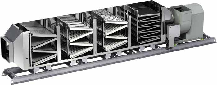
Pollution Control Units

Y            Grease Trapper™
H
                                                           UNIT LENGTH
T                                                                                                                                          INLINE
TH                                                                                                                                          FAN
                                                                                                                                           WIDTH

                *MINIMUM 36 INCHES OF CLEARANCE REQUIRED ON DOOR ACCESS SIDE                                  UTILITY
                 FOR SERVICE AND REMOVAL OF FILTERS                                                            FAN
                                                                                                              WIDTH
      UNIT LENGTH
                                                                   INLINE                                         UNIT
                                                                    FAN                                           WIDTH
                                                                   WIDTH

                                                                                                    HEIGHT

 ANCE REQUIRED ON DOOR ACCESS SIDE                                                                                                   *MINIMUM 36 INCHES OF CLEARANCE R
F FILTERS                                                                                                                             FOR SERVICE AND REMOVAL OF FILTER

                Model    Maximum                                                                 Maximum Fan            Overall Length    Unit Weight
                                      Height (Inches)    Width (Inches)         Fan Type
                GFPS       CFM                                                                   Width (Inches)            (Inches)        (Pounds)
                                                                            Utility Fan Set      29 (737 mm)        207 (5,258 mm)          1142
                    30    3,000       37 (940 mm)       27 (686 mm)
                                                                              Inline Fan         36 (914 mm)        207 (5,258 mm)          1196
                                                                            Utility Fan Set      32 (813 mm)        212 (5,385 mm)          1250
                    45    4,500      49 (1,245 mm)      27 (686 mm)
                                                                              Inline Fan        41 (1,041 mm)       201 (5,105 mm)          1325
                                                                            Utility Fan Set      36 (914 mm)        225 (5,715 mm)          1810
                    60    6,000      64 (1,626 mm)      27 (686 mm)
                                                                              Inline Fan        46 (1,168 mm)       217 (5,512 mm)          1850
                                                                            Utility Fan Set     51 (1,295 mm)       223 (5,664 mm)          2100
                    90    9,000      53 (1,346 mm) 50 (1,270 mm)
                                                                              Inline Fan        56 (1,422 mm)       210 (5,334 mm)          2115
                                                                            Utility Fan Set     53 (1,346 mm)       231 (5,867 mm)          2550
                120       12,000     64 (1,626 mm) 50 (1,270 mm)
                                                                              Inline Fan        61 (1,549 mm)       217 (5,512 mm)          2665
             Dimensions are subject to change pending final fan selection. Consult unit submittals for exact dimensions.
             Type and volume of cooking and cooking fuel must be factored in when selecting unit. Consult factory for final selection.

         4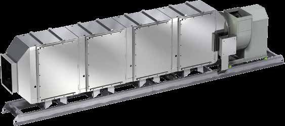
Pollution Control Units

Grease Trapper ESP™

The Grease Trapper ESP Pollution Control Unit uses electrostatic precipitator modules and carbon filters
to remove grease, smoke and odors from the exhaust airstream. UL listed to both UL 8782 - Pollution
Control Units for Commercial Cooking, and UL 867 - Standard for Electrostatic Air Cleaners solidifies the
Grease Trapper ESP as one of the safest pollution control units in the market.
The automated wash down sequence allows for the grease buildup on the ESP collector plates to be
easily removed with the touch of a button or on an automatic daily schedule.
The unique construction of the Grease Trapper ESP allows for the smallest clearance to combustibles in
the industry. It can mount within 12-inches (305 mm) of combustibles on the top of the unit and 6-inches
(152 mm) on the sides and bottom to easily fit it into tight mechanical rooms or ceiling spaces.

How it Works
As air enters the ESP module it passes                                               12 kVdc    6 kVdc
                                                            Dirty Air   Pre-Filter   Ionizer    Collector          Clean Air
through an ionizer that positively charges
the particles in the airstream. Upon entering
the charged collector portion of the cell, the
positively charged particles are attracted
to the negatively charged plates like a
magnet, which captures and removes
the contaminant from the airstream.
This eliminates the need to change
out costly filters and lowers overall                                                      Power
                                                                                           Supply
maintenance requirements.

Durable ESP Cells
• Lightweight cells allow for easier handling and removal from unit
• U
   niversal cell size eliminates the possibility of loading cells in the wrong
  order or position
• T
   hermoset isolators provide improved reliability and reduced weight,
  unlike ceramic isolators that can break easily
• S
   tainless steel spiked blade ionizer improves reliability and will not break
  easily like tungsten wire systems
• C
   ells have been third-party tested to ensure the highest performance
  and efficiency

UL 8782 Pollution Control Units for Commercial Cooking                       L/cUL Listed to UL 867 Electrostatic
                                                                             U
                                                                             Air Cleaners Standards
• Under this listing, the unit is tested under extreme loading
  conditions, similar to how grease ductwork is tested. This                 • U
                                                                                L 867 is a safety standard for the electronics of
  listing details pollution control unit specific construction,                Electrostatic Air Cleaners and more specific for the
  material and electrical requirements to ensure the safety of                 Power Supply and ESP Cell assemblies. The Grease
  the building and its occupants.                                              Trapper ESP electrical assemblies were tested to UL
                                                                               867 Standard requirements and meets or exceeds
• International Mechanical Code (IMC) 2021 will require all
                                                                               the standard as listed.
  pollution control units installed in commercial cooking
  operations to be listed to UL 8782.

                                                                                                                                      5
Pollution Control Units
Grease Trapper ESP™
Keypad or Touchscreen Control Additional Options
• NEMA-1 indoor • For solid fuel appliance applications, three ESP
mounted control panel ALL LIGHTS
ON/OFF
ALL FANS
ON/OFF
100%
OVERRIDE
CLEAN
HOOD
DETERGENT
INDICATOR
10:11:57
TEMP INTERLOCK
INDICATOR
modules and two carbon modules handle the
• M
otor starter or variable
INDIVIDUAL
LIGHT ON/OFF
INDIVIDUAL
FAN ON/OFF
AUTO
TEMPERING
GAS RESET
ON/OFF
PCU FILTER
STATUS
ENERGY SAVINGS
INDICATOR
100
75
50
higher grease and smoke loading
OFF
25
0
88%
frequency drive (VFD) for • Unit can be constructed in multiple sections for
100 100
75 75
50 50
25 25
0 0
1 2 3 4 1 2
complete motor control field assembly if required
EXHAUST FAN SUPPLY FAN
SYSTEMFAULT
and protection HOODS LIGHTS
• NEMA-1 and NEMA-4 fire cabinets with internal
MORE
• U
nit status lights allow kitchen MENU
NAV
heaters are available for indoor or outdoor
personnel to quickly verify unit mounting locations to protect your fire system
operation components and save installation time
1
16
3
4 5
2
8
9
10 14 15
11
6 12
13
7
1 actory inlet transition fabricated to match ductwork for
F 10 Automatic wash down uses detergent from five-gallon
ease of installation tank to clean the entire cell. Reduces the need for
manual cleaning
2 Tool-less access by means of 270 degree turning latches
on doors 11 Pre-piped UL 300 fire system
3 Unit mounted power pack supply the electrostatic 12 V-bank “2” carbon trays for reducing cooking odors
precipitator cells with the necessary voltage for operation
13 Integral mounting rails provide base for unit modules and
4 Modular stainless steel construction exhaust fan
5 Plug and play cables – pre-wired from the factory or up to 14 Accurex UL 762 utility set fan with motor and drive
150 ft pre-made plug n play cables provided for an easy install mounted outside of the airstream per NFPA96
6 Detergent injection manifold – pre-engineered assembly 15 Main control cabinet (shown as unit mounted – remote
for water, detergent injection and mixed wash to unit mounted also available) connects to unit components
wash inlet via plug n play cables
7 Drain outlet (2”) part of manifolded system pre-assembled 16 Detergent control center and assembly – contains the
from the factory, so only one drain is connected in the field. detergent pump and five-gallon bucket that houses the
detergent for wash. The bucket is also monitored to
8 Inlet hot water connection from detergent manifold for ensure you are washing with detergent
automatic washdown system
9 Impingement filter evenly distributes airflow and stops
large particles from entering the system. These filters are
washed, unlike other precipitators on the market
6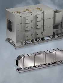
Pollution Control Units

             Grease Trapper ESP™

                                                           UNIT LENGTH

                                                                                 UTILITY
                                                                                  FAN
                                                                                 WIDTH
                                                                                                                                       UNIT LENGTH
                                       INLINE                                     UNIT
                                        FAN                                       WIDTH
                                       WIDTH

                                                                       HEIGHT

CCESS SIDE                                                                                           *MINIMUM 36 INCHES OF CLEARANCE REQUIRED ON DOOR ACCESS S
                                                                                                      FOR SERVICE AND REMOVAL OF FILTERS
                           Maximum           Height         Overall Length                               *Maximum Unit Width      Unit Weight
               Housing                                                                Fan Type
                             CFM            (Inches)           (Inches)                                        (Inches)            (Pounds)

                                                47              180              Utility Fan Set                                      1839
                 15         1,500                                                                          37 (940 mm)
                                         (1,194 mm)         (4,572 mm)              Inline Fan                                        1859
                                                47              187              Utility Fan Set                                      2228
                 30         3,000                                                                          54 (1,372mm)
                                         (1,194 mm)         (4,750 mm)              Inline Fan                                        2258
                                                47              189              Utility Fan Set                                      2609
                 45         4,500                                                                         72 (1,829 mm)
                                         (1,194 mm)         (4,801 mm)              Inline Fan                                        2767
                                              67                191              Utility Fan Set                                      3459
                 60         6,000                                                                         51 (1,295 mm)
                                         (1,702 mm)         (4,851 mm)              Inline Fan                                        3541
                                              67                195              Utility Fan Set                                      4243
                 90         9,000                                                                         72 (1,829 mm)
                                         (1,702 mm)         (4,953 mm)              Inline Fan                                        4277
                                              93                222              Utility Fan Set                                      5000
                135        13,500                                                                         72 (1,829 mm)
                                         (2,362 mm)         (5,639 mm)              Inline Fan                                        4819
             * Maximum width includes fan, power pack, motor clearance, and unit width. Unit access clearance is not accounted for.

                                                       Learn more at Greenheck.com
                                                                                                                                                     7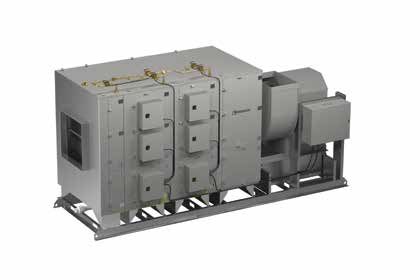
Design and Selection Support

    Enjoy Greenheck’s extraordinary service, before, during and after the sale.
    Greenheck offers added value to our wide selection of top performing, energy-
    efficient products by providing several unique service programs.
                      Our Quick Delivery program ensures shipment of in-stock
                       products within 24 hours of placing your order. Our Quick
COLORS
GREEN- CMYK C-54 M-0 Y-100 K-0 RGB R-130 G-195 B-65   BLUE- CMYK C-100 M-56 Y-0 K-18 RGB R-0 G-90 B-156

                       Build made-to-order products are manufactured in
                       1-3-5-10-15 or 25-day production cycles, depending upon
                       its complexity.
                                                                                                           reenheck’s free computer aided product selection program
                                                                                                          G
                                                                                                          CAPS®, rated by many as the best in the industry, helps you
                                                                                                          conveniently and efficiently select the right products for the
                                                                                                          challenge at hand.
                                                                                                           ur 3D service allows you to download, at no charge, easy-
                                                                                                          O
                                                                                                          to-use AutoDesk® Revit® 3D drawings for many of our
                                                                                                          ventilation products.
    Find out more about these special services at greenheck.com

   Building Value in Air
   Greenheck delivers value                                                                                         top quality, innovative air-     And building owners and
   to mechanical engineers by                                                                                       related equipment. We offer      occupants value the energy
   helping them solve virtually                                                                                     extra value to contractors       efficiency, low maintenance
   any air quality challenges                                                                                       by providing easy-to-install,    and quiet dependable operation
   their clients face with a                                                                                        competitively priced, reliable   they experience long after the
   comprehensive selection of                                                                                       products that arrive on time.    construction project ends.

   Our Commitment
   As a result of our commitment to continuous improvement, Greenheck reserves the right to change
   specifications without notice.
   Specific Greenheck product warranties are located on greenheck.com within the product
   area tabs and in the Library under Warranties.

                                                                                                                                                                                               00.KIT.1019 R2 10-2020
   P.O. Box 410 • Schofield, WI 54476-0410 • Phone (715) 359-6171 • greenheck.com                                                                                                Copyright © 2020 Greenheck Fan Corp.
You can also read