Improving the torque direct control method of the asynchronous motor in the converter using the active rectifier - IOPscience
←
→
Page content transcription
If your browser does not render page correctly, please read the page content below

Journal of Physics: Conference Series

PAPER • OPEN ACCESS

Improving the torque direct control method of the asynchronous motor in
the converter using the active rectifier
To cite this article: A.E Kozyaruk et al 2021 J. Phys.: Conf. Ser. 1753 012025

View the article online for updates and enhancements.

                                This content was downloaded from IP address 46.4.80.155 on 27/02/2021 at 14:50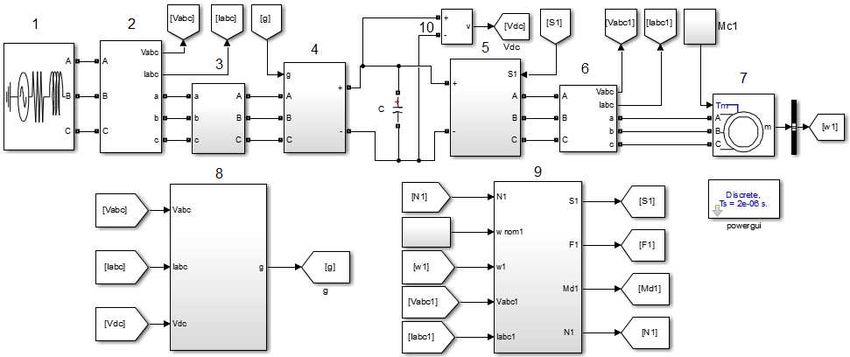
IPDME 2020                                                                                                      IOP Publishing
Journal of Physics: Conference Series                         1753 (2021) 012025          doi:10.1088/1742-6596/1753/1/012025

Improving the torque direct control method of the
asynchronous motor in the converter using the active rectifier

                     Kozyaruk A.E1, Le Van Tung1,2, Bogdan Vasilev1
                     1
                       St. Petersburg Mining University, 2, 21 Line of Vasilyevsky Island, St.
                     Petersburg,199106, The Russian Federation
                     2
                       Quang Ninh University of Industry, 18 street, Yen Tho Ward, Quang Ninh province,
                     208830, Viet Nam

                     E-mail: levantungdktd@gmail.com

                     Abstract. The frequency converter study has shown that controlled rectifiers, also known as
                     active rectifiers, have many advantages over uncontrolled rectifiers (diode bridges). The
                     frequency converter with an active rectifier ensures that the input current is sinusoidal, the
                     power factor is 1, the DC voltage constant at the output, the energy exchange according to
                     bidirectional is between the load and grid. The voltage oriented control for the active rectifier
                     will measure the grid voltage and use current control circuits or instantaneous power control
                     circuits. The paper analyses the advantages of using the method of controlling the current in
                     the rectifier circuit when working with the three-phase motor load. The torque direct control
                     method of the motor is enhanced by selecting a new switch table of the voltage vector. The
                     combining power, an active rectifier circuit, inverter, motor, and load create a complete electric
                     drive system with improved working efficiency. The research results were verified by
                     Matlab&Simulink software.

1. Introduction
Currently, the diode rectifier and thyristor rectifier are commonly used. These rectifiers have
advantages such as very low initial investment, operation, maintenance, repair. At the same time, the
diode and thyristor valves are capable of working with high currents and voltages, so they are used a
lot in applications requiring very large capacity. However, the main disadvantages of these rectifiers
are their nonlinearity and distortion of the current and voltage of the grid. In frequency converters with
diode rectifiers, the power is only transmitted in one direction. When using the thyristor, there are
many circuit diagrams in practice to ensure a two-way power transmission. However, the diagram is
cumbersome, there is low efficiency and it is difficult to control [1-3]. Currently, active rectifiers using
fully controlled switching valves (IGBT) are being developed and applied in practice. These rectifiers
control the charging current for the capacitor, so the DC voltage at the output of the rectifier can be
controlled. This is the advantage of an active rectifier [4-6].
    Active rectifiers, using the voltage oriented control (VOC) method, will estimate the grid voltage
and then control the current. This method has advantages such as a fixed switching frequency in order
to design a simple input filter block, which takes advantage of the PWM modulation method [7]. The
combination of an active rectifier with the inverter and the speed control of a three-phase AC motor
will ensure energy is exchanged in two directions between the grid and the load. During operation, the

              Content from this work may be used under the terms of the Creative Commons Attribution 3.0 licence. Any further distribution
              of this work must maintain attribution to the author(s) and the title of the work, journal citation and DOI.
Published under licence by IOP Publishing Ltd                          1
IPDME 2020 IOP Publishing
Journal of Physics: Conference Series 1753 (2021) 012025 doi:10.1088/1742-6596/1753/1/012025
induction motor can work at all four quadrants of the coordinate system. Direct torque control (DTC)
has a fast torque response, low torque ripple, and stable switching frequency so the motor is stable at
low speed or when the torque is changed [8, 9]. The basic DTC control method uses a six-sector
switch table that has disadvantages such as a torque controller, which is a delay relay (two positions),
so it has a large torque error and the torque amplitude fluctuates when the torque load changes [9, 10].
This paper will study the switching table with twelve new vectors. The controller ensures a faster
response when torque fluctuates, the amplitude is kept at the required level, and the control process is
more accurate. Combining the method of active rectifier control with the inverter and direct torque
control will improve the quality of electric drive systems in practice.
2. Methods
2.1. Direct current control method of an active rectifier
The direct current control (DCC) structure is based on the conversion between the fixed coordinate
system α-β and the rotating coordinate system d-q. The measured values in the natural coordinate
system abc are first converted to the fixed coordinate system α-β, then converted to the rotating
coordinate system d-q as shown in figure 1. This method ensures a stable output DC voltage and high
static efficiency through internal current control circuits. In figure 2, the load is an inverter and a
three-phase ac motor; PI – Regulators of current along the d - q axis and direct voltage regulators
(DC); PWM – IGBT control pulse generator; L – Line inductance has the function of not giving input
short circuit and is the booster unit; CM&LVE – Current measurement & line voltage estimation.
Figure 1. Structure of PWM rectifier according to DC
In the coordinate system d-q the grid voltage is calculated as follows:
di
u Ri L u ωLi
dt
di
u Ri L u ωLi
dt
Assuming the input resistance is extremely small compared to the input inductance, the minimalist
formula becomes:
di
u L u ωLi
dt
di
u L u ωLi
dt
The iqref current is set to 0 to always ensure the input power factor is 1 and will result in the
formula:
2IPDME 2020 IOP Publishing
Journal of Physics: Conference Series 1753 (2021) 012025 doi:10.1088/1742-6596/1753/1/012025
di
u L u
dt
0 u ωLi
The idref current at the DC voltage regulator output (PI) is then compared with the converted current
value by converting coordinates (abc) to (α - β) and (d - q). The error of comparison is the input of the
controller. In the control structure, the current value iqref is constant. The goal is that the tracking
control requires an integral stage to eliminate static errors. So select the current regulator with the PI
structure to eliminate noise and eliminate static errors. Also, when dividing the current in two d - q
axes, there will be a mutual inductance phenomenon between the axes. To eliminate these cross
components we use a decoupled controller as shown in Figure 2.
The PI regulator in the voltage loop works to keep the Udc voltage constant on capacitor C
according to the set value, that is, control the flow of active power flowing to the capacitor C. Always
ensure the output voltage of the rectifier is equal to the Udcref set value when the load changes.
Figure 2. Current and dc-link voltage controller
2.2. Method of direct control of torque
The DTC torque control method is widely used in the industry. With advantages such as very small
torque response time and high reliability, formulas can be used to estimate rotor speed without using a
speed sensor. Torque control is a control that ensures the amplitude of the stator flux vector and the
torque is kept within the permissible range. The error between the two calculation steps depends on
the sampling frequency. The basic DTC control method using a switch table having six sectors (figure
3) only creates two control areas: increasing and decreasing torque, so the controller response will be
slow as the torque of the load changes continuously.
During DTC control the vector of the output voltage of the autonomous inverter is calculated based
on the switching algorithm which is constructed based on table 1. The output signals of the relay
regulators and the number of the sector in which the vector of flux linkage of the stator is located flow
into the switching table. In table 1 the following symbols represent:
FI – increase in flux linkage of the stator;
FD – decrease in flux linkage of the stator;
MI – increase in the moment of the motor;
M – the moment of the motor corresponds to the given value;
MD – decrease in the moment of the motor.
Control of moment in motor AC within the DTC system is unstable as the size of flux linkage of
the stator and the moment constantly changes in the range which is defined by insensitive regulators.
Also, the range of pulsations depends on the frequency of switching the autonomous inverter. Based
on the provision of a vector of flux linkage of the stator, reduction or increase in torque voltage vector
corresponds to table 1. If on the switching period the size of the moment goes beyond a tolerance
zone, then the chosen vector of the voltage of the autonomous inverter is replaced with another. Thus,
3IPDME 2020 IOP Publishing
Journal of Physics: Conference Series 1753 (2021) 012025 doi:10.1088/1742-6596/1753/1/012025
the DTC system doesn't allow providing a constant value of moment for the motor AC, and that is a
disadvantage.
β Table 1. The switching table of the switch table
N3 N2 with six sectors
V2
V3 dΨ dM N1 N2 N3 N4 N5 N6
MI V2 V3 V4 V5 V6 V1
V4 V1 N1
V0,7 FI M V0 V7 V0 V7 V0 V7
N4
α
MD V6 V1 V2 V3 V4 V5
V5
V6 MI V3 V4 V5 V6 V1 V2
N5 N6 FD M V7 V0 V7 V0 V7 V0
MD V5 V6 V1 V2 V3 V4
Figure 3. Splitting the phase plane into six
direct sectors
The main way modification of the DTC system is to change its switching table, which the structure
changes in two ways:
- Change of types of regulators;
- Change in quantity of sectors of a phase plane.
The maximum effect is reached by the use of both ways in a complex. It is advisable to carry out
the transition to the 12 sectors splitting the phase plane. We will consider these ways of modification
of the DTC systems.
When splitting the phase plane into 12 sectors the size of each sector is 300. The 12th sector
splitting the phase plane is shown in fig 4.When adjusting the torque, the actual value of the motor
torque can vary widely. To estimate the magnitude of the torque in Fig. 5, the following regions are
selected:
I – zone of the sharp increase of the torque;
D – zone of the sharp decrease of the torque;
SI – zones of the slight increase of the torque;
SD – zones of the slight decrease of the torque.
The change of moment is shown in fig. 5.
β Md
V3(010) V2(110) dM = 2 D
N4 N3 MD
N5 N2
dM = 1 SD
N6
N1 MSD
V4(011 V0,7 V1(100) ∆M b
) α dM= 0
Md *
N7 N12
dM = 0
N8 N11 MSI
N9 N10
SI
V5(001 V6(101) dM = -1
MI
)
dM = -2 I
Figure 4. DTC method with 12 sectors Figure 5. Control field of Md moment
4IPDME 2020 IOP Publishing
Journal of Physics: Conference Series 1753 (2021) 012025 doi:10.1088/1742-6596/1753/1/012025
Whereby Md – the operating value of moment on the motor shaft; Md* – given moment value and
Mb - a tolerance zone of the regulator of the moment.
Communication between Mb and M is caused by the following. In the table of the switching
with 12 sectors, if the value of | M – Mb | is rather high, the moment needs to be changed to quickly
bring the system to a stable state. In the opposite state, when | M - Mb| it is relatively little for the
stabilization of the system because it only requires a small change. Therefore there has to be an
accurate difference between the required value of the moment. Thus in the DTC system in a contour
regulation of the moment, it is necessary to use 4-level regulators. The output signal of a 4-level
regulator which depends on the number of misalignment is explained as follows:
dM = 2, if ∆M>MD – Md
dM = 1, if 0.5(MD - Md) < MIPDME 2020 IOP Publishing
Journal of Physics: Conference Series 1753 (2021) 012025 doi:10.1088/1742-6596/1753/1/012025
Where:1 – three-phase source; 2, 6 – AC current and voltage sensors; 3 – inductance; 4 – active
rectifier circuit (IGBT); 5 – voltage inverting circuit (IGBT); 7 – asynchronous motor; 8 – active
rectifier control unit by DCC method; 9 – direct torque control unit (DTC); 10 – DC voltage sensor;
Mc – load torque.
To study the working quality of the electric drive system, in the beginning, the motor speed and
torque increased. When the system is working stably, the load torque suddenly reverses. These are the
two most strict changes when the asynchronous motor works as shown in figure 7 and figure 8.
Figure 7. Set motor speed Figure 8. Set load torque
The simulation results are as follows:
Figure 9. AC input voltage Figure 10. Input current (same phase angle with
voltage)
Figures 9 and 10 show the grid current in the standard sine form and it has a phase angle equal to
the phase angle of the voltage at the input of the active rectifier.
Figure 11. DC output voltage (Udc = 690V ) Figure 12. Grid current with reverse load torque
at t = 0,15s (Mc = -16 N.m)
Figure 11 shows that at the output of the positive rectifier, the DC voltage is equal to the preset
voltage value (Udc = 690V). Demonstrate that the control system for the active rectifier works well and
meets the requirements.
6IPDME 2020 IOP Publishing Journal of Physics: Conference Series 1753 (2021) 012025 doi:10.1088/1742-6596/1753/1/012025 Figure 13. Current harmonics at active rectifier Figure 14. Active power of the rectifier input input (TDH=1,82%) Figure 13 shows the grid current harmonics are very small and the total harmonic distortion of the current THD = 1,82%. Figure 14 shows at time t = 0,15s, the reactive load torque Mc = -16 N.m, the asynchronous motor works in the generator mode. Active power (p
IPDME 2020                                                                                IOP Publishing
Journal of Physics: Conference Series          1753 (2021) 012025   doi:10.1088/1742-6596/1753/1/012025

 Figure 19. Stator magnetic flux graphic with        Figure 20. Stator magnetic flux graphic with
 switch table having six sectors                     switch table having twelve sectors
    Figures 19 and 20 shows that the method of using twelve sectors switch table has a circular motor
magnetic flux trajectory than the six sectors method. This shows that the stator current by the method
of twelve sectors with small harmonic content.

3. Conclusion
Theoretical analysis and the results obtained from simulation show that the frequency converter with
an active rectifier has more advantages than the inverter with a rectifier diode. The energy is
exchanged in two directions when braking occurs, there is a high power factor, there is a sine-grid
current and the harmonic content is reduced. The direct torque control method using a switch table has
twelve sectors to ensure that the rotation speed is always tracking to the set value, the electromagnetic
torque responds quickly to changes of load torque, and the magnetic torque has lower adjustment. This
research aims at improving the DTC control method in a 4Q frequency converter by using the new
voltage switch table (twelve sectors) to ensure the high quality of the actual electric drive control
system.

References
[1] Ahmed Riyaz, Atif Iqbal 2009 International Journal of Engineering, Science and Technology
1(1) 90-105
[2] W. Guo, T. Mingxing and R. Enen 2010 The 2nd International Symposium on Power
Electronics for Distributed Generation Systems 5 791-795
[3] B. Yu.Vasil'ev, V. A.Shpenst, O. V. Kalashnikov, and G. N. Ul'yanov 2018 Zapiski Gornogo
Instituta/Journal of Mining Institute 229 41-49
[4] Malinowski, M 2001 M. Malinowski//Ph.D. Thesis. Warsaw p 128 (in Poland)
[5] A. Anuchin, D. Shpak, A. Zharkov 2017 IEEE 58th International Scientific Conference on
Power and Electrical Engineering of Riga Technical University (RTUCON),Rigapp 1-5
[6] Zhukovskiy Y, Korolev N and Koteleva IN 2018 IOP Conf. Series: Journal of Physics: Conf.
Series 1015(3) 032158 DOI: 10.1088/1742-6596/1015/3/032158
[7] Xiao, P., Corzine, K.A., and Venayagamoorthy, G.K 2010 IEEE Transactions on Power
Electronics 23(4) 2006-2017
[8] Alekseev V V, Emel’yanov A P, Kozyaruk A E 2016 Russian Electrical Engineering 87(4)
181-188 DOI: 10.3103/S1068371216040027
[9] Bogdan .Y, Le Van Tung 2018 IEEE Trans. Rus 80-87
[10] Tereshkin V M, Grishin D A, Makulov I A 2019 Journal of Mining Institute 240 678-685
DOI:10.31897/pmi.2019.6.678

                                                    8
You can also read