SM2400 Serial-2-PLC Adapter User's Guide
←
→
Page content transcription
If your browser does not render page correctly, please read the page content below
Communication Technology by:
              Semitech Semiconductor

SM2400 Serial-2-PLC Adapter
                User’s Guide

                            UG-SM2400–-177A–-02/2019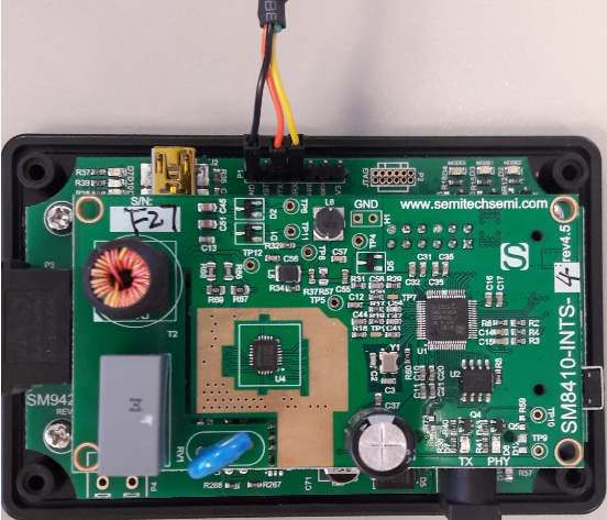
This publication contains proprietary information which is subject to change without notice and is supplied ‘as
is’, without any warranty of any kind.

Revision History
  Revision Number           Date                                            Tasks

         A                 02/2019        SM2400 Serial-2-PLC Adapter User’s Guide initial release.

                                                                                     SM2400 EVK User’s Guide              2
                                                                                               UG-SM2400–-177A–-02/2019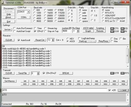
Table of Contents
1. Introduction .....................................................................................................................................4
2. Features ..........................................................................................................................................4
3. Hardware Connection .....................................................................................................................5
    3.1 Evaluate ASCII Pass-through Using the SM2400-EVK2 .........................................................5
    3.2 Replacing the RS485 Bus with Power Line via SM2400-EVK2 with ASCII Pass-through .....5
4. ASCII Pass-through Configurations ................................................................................................7
    4.1 Supported AT Commands .......................................................................................................7
    4.2 Supported AT Registers ..........................................................................................................7
    4.3 Supported Baud Rates ............................................................................................................8
    4.4 Factory Defaults ......................................................................................................................8
5. ASCII Pass-through Using USB to TTL RS232 Adaptor with SM2400-EVK2 ................................9
    5.1 Hardware Connection ..............................................................................................................9
    5.2 Download ASCII Pass-through Firmware ..............................................................................10
    5.3 Send Text Message Using a Serial Terminal ........................................................................11
6. Example Application .....................................................................................................................14
7. References ...................................................................................................................................15

                                                                                      SM2400 Serial-to-PLC Adapter User’s Guide                           3
                                                                                                                        UG-SM2400–-177A–-02/2019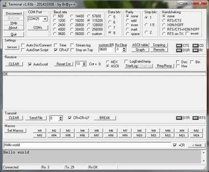
1. Introduction
     The serial-to-PLC adapter is a simple way to extend/replace an existing serial connection with a PLC without hav-
     ing to change any other software or hardware components. The adapter utilizes pass-through firmware that con-
     verts bytes from a serial port to PLC and from PLC to serial port.

     There are two pass-through variants:

     ASCII pass-through: Copies all ASCII characters, which are received on the UART, verbatim to the PLC line. Con-
     versely, it forwards all ASCII characters received from the PLC line verbatim to the UART. The transmission to the
     power line in ASCII pass-through is triggered by the reception of a special ASCII character, normally "End of Line"
     or "Carriage Return" and can be changed on request. The configuration in ASCII pass-through mode can be
     changed using AT commands.

     TP pass-through: This variant of the pass-through firmware forwards all bytes from the UART (not necessarily
     ASCII) to the PLC line, and, conversely, forwards all bytes received from the PLC line verbatim to the UART. The
     transmission to the power line in TP pass-through mode is triggered by a time-out. Hence the name ‘Timeout-
     based Packetization (TP)’. The limitation of this mode is that there is no way to change the configuration.

     Note: At this time the ASCII pass-through and the TP pass-through firmware does not support the protocol used by
     the Semitech Graphical User Interface (GUI), which is available on most other firmware packages. Consequently, it
     cannot be used to communicate with the Serial-to-PLC adapter. Use serial terminal applications instead.

     The SM2400 PLC device with ASCII pass-through or TP pass-through is ideal for industrial control applications to
     replace or extend RS232 or RS485 connections without having to modify other parts of the systems or any of the
     software protocols.

     At the end of this document, two SM2400-EVK2 adapters with TP pass-through firmware are used as an example
     of the serial-to-PLC adapter application.

2. Features
     • Replacement of RS232 cable with DC or AC power line
     • Replacement of RS485 multi-drop network with DC or AC power line
     • Supports Modbus protocol
     • Operational band: FCC (Cenelec-B/C version available)
     • PLC PHY: OFDM (G3 FCC) or XXR (when additional performance is required)
     • Effective PHY data rate up to 300 kbit/s (depending on band used)
     • Serial port interface speed: up to 625 kbit/s
     • Packet size: up to 350 characters
     • Seamless PLC transmission with retries to improve performance
     • Fully transparent mode (TP passthrough), plug and play coming out of the box without the need for any
       programming
     • Serial and PLC configuration parameters are accessible via AT commands (ASCII pass-through)

                                                                  SM2400 Serial-to-PLC Adapter User’s Guide             4
                                                                                             UG-SM2400–-177A–-02/2019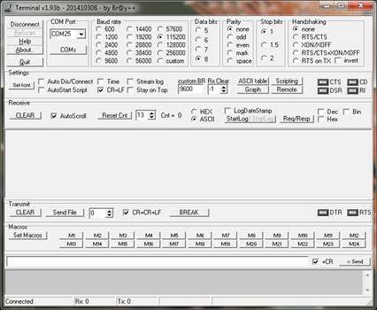
3. Hardware Connection
3.1 Evaluate ASCII Pass-through Using the SM2400-EVK2

     The SM2400-EVK2 can be used to evaluate ASCII pass-through by connecting an RS232 device to the host inter-
     face P1 header on the base board of the SM2400-EVK2 as shown below.

                            Figure 1. P1 Header on the SM2400-EVK2 Base Board

                                            Table 1. P1 Header Pin List
                                      Pin#                    Name
                                       P1       3V3
                                       P2       Mode1
                                       P3       RS485 Data Enable
                                       P4       EX_UART_RX
                                       P5       EX_UART_TX
                                       P6       Reset
                                       P7       GND

3.2 Replacing the RS485 Bus with Power Line via SM2400-EVK2 with ASCII Pass-through

     This section shows the difference between the older RS485 bus network (Figure 2) and the newer RS485 bus net-
     work with RS232 devices (Figure 3) and RS485 devices (Figure 4).

                                                        RS485 Bus
                  Master

                                     Slave 1             Slave 2          Slave 3         Slave 4

                                      Figure 2. Old RS485 Bus Network

                                                                    SM2400 Serial-to-PLC Adapter User’s Guide          5
                                                                                            UG-SM2400–-177A–-02/2019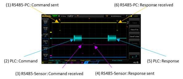
SM2400                                Power Line
  EVK2

  RS232                SM2400            SM2400                SM2400              SM2400
  Master                EVK2              EVK2                  EVK2                EVK2

                       RS232             RS232                 RS232                RS232
                       Slave 1           Slave 2               Slave 3              Slave 4

             Figure 3. New Power Line RS485 Bus Network with RS232 Devices

S M 2400                               P ow er Line
 EVK2

R S 232 to            S M 2400          S M 2400               S M 2400             S M 2400
 R S 485               EVK2              EVK2                   EVK2                 EVK2

 R S 232             R S 232 to         R S 232 to            R S 232 to           R S 232 to
 M aster              R S 485            R S 485               R S 485              R S 485

                       R S 485           R S 485                R S 485              R S 485
                       S lave 1          S lave 2               S lave 3             S lave 4

               Figure 4. New Power Line RS485 Network with RS485 Devices

                                                      SM2400 Serial-to-PLC Adapter User’s Guide          6
                                                                              UG-SM2400–-177A–-02/2019
4. ASCII Pass-through Configurations
      This section describes the supported features of the ASCII pass-through configuration, including AT commands,
      AT registers, baud rates, and factory defaults.

4.1 Supported AT Commands

      Table 2 lists the supported AT commands.
                                              Table 2. Supported AT Commands
              Command                                                      Description
                 +++              Switch to command mode.
                 ATO              Switch to data (string tx) mode; this command ends with Satin letter "O", not with zero.
                 ATSr?            Get Register r.
                 ATSr=            Set Register r.
                 ATZ              Reboot device.
                 AT&F             Restore Factory Defaults (most defaults depend on PHY, see below).
                AT&MBM            Make master.
                AT&MBS            Make slave (requires address as argument).
                AT&MBC            Run given command.

      Note: When running ASCII pass-through firmware for the first time, it is important to run the AT&F command fol-
      lowed by the ATZ command. This is required to write ASCII-specific default settings to the Flash memory.

4.2 Supported AT Registers

      Table 3 lists the supported AT registers.

      Note that register numbers 100 and above may be used for advanced physical-level PLC configuration. The altera-
      tion of these parameters from their default values is usually not required. However, in challenging circumstances,
      e.g. high interference or noise, this may be an option. The applicability and meaning of such settings depends on
      the PLC protocol. For more information, refer to the documents listed in Section 7, References, or contact Semi-
      tech Semiconductors should fine tuning of the physical parameters be required.
                                               Table 3. Supported AT Registers
  Register Number
        37               UART baud rate (37 is standard allocation for this purpose).
      100-200            PLC PHY configuration parameters.
        100              Modulation code, 0 to 6.
        101              Bits per baud.
        102              Number of repetitions.
        103              Number of frequencies.
        104              Convolution code enable.
                         1: enable
                         0: disable
        105              Tone map. A bit map containing a list of the sub-bands (groups of tones) that are either active (bit set to 1) or
                         inactive (bit set to zero). A bit in the bit map represents a group of consecutive tones and the number of tones
                         per group depends on the band plan.
        106              Coherent mode.
                         1: enable
                         0: disable

                                                                             SM2400 Serial-to-PLC Adapter User’s Guide                       7
                                                                                                            UG-SM2400–-177A–-02/2019
Table 3. Supported AT Registers (continued)
Register Number
107 Delimiter.
0: SOF no response
1: SOF w/ response
2: ACK
3: NACK
108 On/Off mode.
1: enable
0: disable
109 Band select; XR-specific setting
110 SubCarriers; 4 decimal concatenated numbers, e.g. set of subcarriers "30 40 50 60" is encoded as 30405060.
111 FCC enable (XXR protocol).
1: enable
0: disable
4.3 Supported Baud Rates
Table 4 defines baud rates, which can be applied to UART using ATS command with register number 37 (conven-
tional register for setting the baud rate).
Table 4. Supported Baud Rates
Mode Baud Rate
0 through 4 600
5 1200
6 2400
7 and 8 4800
9 9600
10 and 11 14400
Note: These higher baud rates might not be standard allocations
12 19200
13 38400
14 57600
15 115200
16 230400
17 375000
18 625000
Example:
ATS37 = 14: baud rate set to 57600
ATS37 = 16: baud rate set to 230400
4.4 Factory Defaults
Following are the default PLC parameters with ASCII pass-through or TP pass-through firmware, which are acces-
sible for modification via AT commands in ASCII pass-through variants.
SM2400 Serial-to-PLC Adapter User’s Guide 8
UG-SM2400–-177A–-02/2019Table 5. Factory Defaults
Parameter/Mode Default
UART baud rate 115200 (mode 15)
XXR Modcod = 1
bitsPrBaud = 1
repetition = 4
Subc2200 = 30405060
G3 Modcod = 0
BitsperBaud = 1
Repetitions = 4
ToneMap = 0x03F
Coherent = 1
Delimiter = 0
5. ASCII Pass-through Using USB to TTL RS232 Adaptor with SM2400-EVK2
ASCII pass-through can also be tested using a USB to TTL RS232 adapter connected to the host interface connec-
tor P1 on the base board of the SM2400-EVK2 as described in the top portion of Figure 5 below.
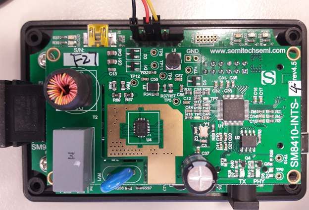
5.1 Hardware Connection
The connection to the UART port is available on the SM2400-EVK2M base board on the header P1, where pin 5 is
external transmit, pin 4 is external receive, and pin 7 is ground as shown below.
This UART port can be connected either directly to the TTL-level UART port on the host device (if available), or to
a USB port via a USB-to-UART converter, also known as FTDI (Digikey Part No. 768-1204-ND). The latter method
of the connection is illustrated by Table 6 and Figure 5.
Table 6. Connecting the FTDI Device to the SM2400-EVK2 Base Board
FTDI TTL-232R-RPi SM2400-EVK2 Base Board
RXD (Yellow cable) EX_UART_RX
(Pin 4 of P1 Header)
TXD (Orange cable) EX_UART_TX
(Pin 5 of P1 Header)
GND (Black cable) GND
(Pin 7 of P1 Header)
Please note that the mini-USB cable and the FTDI cable can't be used at the same time.
SM2400 Serial-to-PLC Adapter User’s Guide 9
UG-SM2400–-177A–-02/2019Figure 5. FTDI TTL-232R-RPi Connection
5.2 Download ASCII Pass-through Firmware
The img-passthru-g3-ascii-fcc bundle can be downloaded to the SM2400-EVK2 FCC module using the
SM2400Control GUI as described in the SM2400-EVK User Guide.
If an FTDI cable is used for downloading, pin 1 (3V3) and pin 2 (Mode1) of header P1 must be connected via a
jumper to pull the Mode1 pin high for downloading. This jumper is shown in Figure 6 below. After the download is
complete, remove the jumper and power cycle the SM2400-EVK2.
If a mini-USB cable is used for downloading, there is no need to manually control the Mode1 pin because it is con-
trolled by the CP2110 on the SM2400-EVK2 base board.
SM2400 Serial-to-PLC Adapter User’s Guide 10
UG-SM2400–-177A–-02/2019Figure 6. - FTDI TTL-232R-RPi Connection for Downloading
5.3 Send Text Message Using a Serial Terminal
After downloading the ASCII pass-through firmware to two SM2400-EVK2 systems, the ASCII messages can be
sent between those two EVK systems over the power line via a serial terminal, e.g. Bray's Terminal
(https://sites.google.com/site/terminalbpp/). This can be accomplished using the following procedure.
1. Connect each SM2400-EVK2 to a PC using the FTDI TTL-232R-RPi cables as shown below.
P o w e r L in e
S M 24 0 0 - SM 2400-
EVK2 EVK2
T T L -2 3 2R T T L -2 32 R
R P i C a b le R P i C a b le
Figure 7. Connecting Each SM2400-EVK2 to a PC
2. Start Terminal.exe
SM2400 Serial-to-PLC Adapter User’s Guide 11
UG-SM2400–-177A–-02/20193. Once the terminal.exe program is invoked, connect the EVK to the terminal via the right COM port at a default baud
rate of 115200 as shown in Figure 8.
Figure 8. Set the Baud Rate to 115200
4. When running the ASCII PASSTHRU project for the first time on the board, which had other projects loaded before, it is
important to run AT&F command followed by ATZ command. This is needed to write ASCII-specific default settings to
flash.
5. Send ATO to switch to data mode.
6. Repeat steps 2 through 4 for the second SM2400-EVK2.
7. Test any ASCII string from one terminal and it should be received and displayed on the 2nd terminal as shown in
Figure 9.
SM2400 Serial-to-PLC Adapter User’s Guide 12
UG-SM2400–-177A–-02/2019Figure 9. Send Hello World from Terminal 1
Figure 10. Received from Terminal 2 with Retries
SM2400 Serial-to-PLC Adapter User’s Guide 13
UG-SM2400–-177A–-02/20196. Example Application
The following example illustrates an off-the-shelf RS485 sensor (inclinometer) managed remotely by introducing
two PLC adapters between the sensor and the PC based GUI in a plug-and-play manner as shown in Figure 11.
The scope image in Figure 12 shows the message propagation from the sensor to the PC and back.
SM2400-EVK2 SM2400-EVK2
Figure 11. RS485 Inclinometer Example Configuration
Figure 12. RS485-to-PLC Message Propagation
SM2400 Serial-to-PLC Adapter User’s Guide 14
UG-SM2400–-177A–-02/2019Figure 13. RS485 Transceiver Circuit to the SM2400-EVK2
7. References
1. Narrowband OFDM PLC specifications for G3-PLC networks, G3-PLC Alliance, April 2015
2. Specification for PoweRline Intelligent Metering Evolution, revision 1.4, Prime Alliance 2014
SM2400 Serial-to-PLC Adapter User’s Guide 15
UG-SM2400–-177A–-02/2019Corporate Office California | USA Adesto Headquarters 3600 Peterson Way Santa Clara, CA 95054 Phone: (+1) 408.400.0578 Email: contact@adestotech.com © 2019 Adesto Technologies. All rights reserved. UG-SM2400--177A–-02/2019 Adesto, the Adesto logo, CBRAM and DataFlash are trademarks or registered trademarks of Adesto Technologies Corporation in the United States and other countries. Other company, product, and service names may be trademarks or service marks of others. Adesto products are covered by one or more patents listed at http://www.adestotech.com/patents. Disclaimer: Adesto Technologies Corporation (“Adesto”) makes no warranties of any kind, other than those expressly set forth in Adesto’s Terms and Conditions of Sale at http://www.adestotech.com/ terms-conditions. Adesto assumes no responsibility or obligations for any errors which may appear in this document, reserves the right to change devices or specifications herein at any time without notice, and does not make any commitment to update the information contained herein. No licenses to patents or other intellectual property of Adesto are granted by Adesto herewith or in connection with the sale of Adesto products, expressly or by implication. Adesto’s products are not authorized for use in medical applications (including, but not limited to, life support systems and other medical equipment), weapons, military use, avionics, satellites, nuclear applications, or other high risk applications (e.g., applications that, if they fail, can be reasonably expected to result in personal injury or death) or automotive applications, without the express prior written consent of Adesto.
You can also read