LORD Axial Isolator Gen 3.5 Use and Maintenance Manual - LORD Corporation
←
→
Page content transcription
If your browser does not render page correctly, please read the page content below

LORD Axial Isolator Gen 3.5
                     Use and Maintenance Manual

UM1004 | MRO-00011   05/21 Rev.0   DCO-016875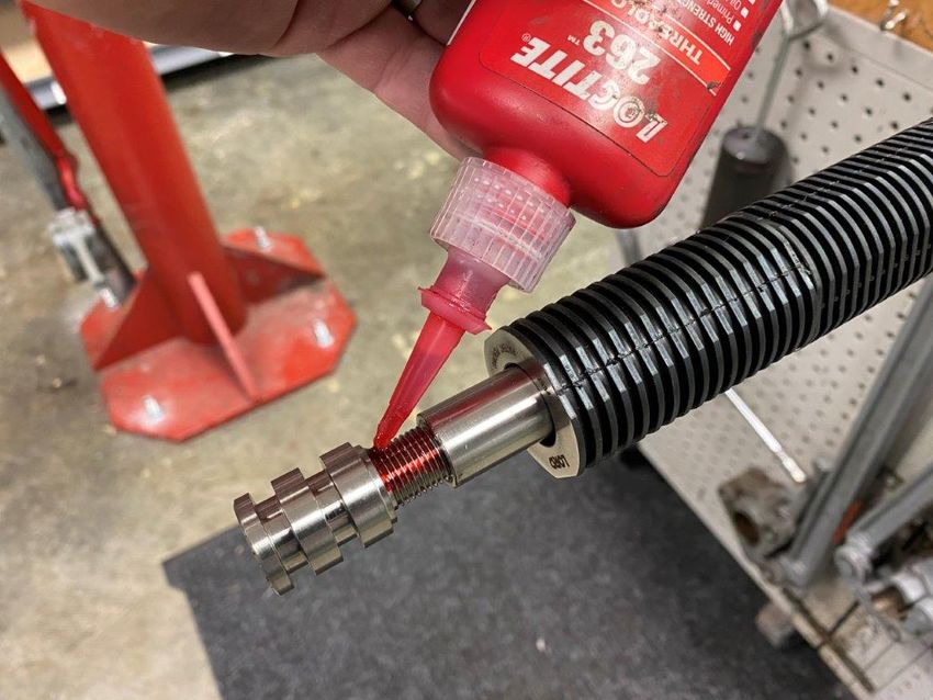
Table of Contents
1.0         INTRODUCTION........................................................................................................................................................ 4
2.0         FUNCTION ................................................................................................................................................................. 4
3.0         ASSEMBLY INTO MWD/LWD TOOL STRING.......................................................................................................... 4
3.1           Mechanical ............................................................................................................................................................ 4
3.2           Pressure Conduit................................................................................................................................................... 4
3.3           Location in MWD String ........................................................................................................................................ 4
4.0         OPERATING PARAMETERS .................................................................................................................................... 5
4.1           Maximum Operating Conditions ............................................................................................................................ 5
4.2           Maximum Static Loads .......................................................................................................................................... 5
4.3           Explosive Decompression ..................................................................................................................................... 5
5.0         PARTS LIST ............................................................................................................................................................... 5
6.0         REDRESS KITS ......................................................................................................................................................... 6
7.0         RECOMMENDED SERVICE KIT STOCK ................................................................................................................. 7
8.0         ILLUSTRATED PARTS LIST (IPL) ............................................................................................................................ 7
9.0         FIELD CHECKS AND MAINTENANCE ..................................................................................................................... 8
9.1            Service Intervals .................................................................................................................................................... 8
9.2            Overall Length (OAL) Inspection [Shoulder-to-Shoulder] ..................................................................................... 9
10.0        SERVICE TOOLS ...................................................................................................................................................... 9
10.1          Standard Tools ...................................................................................................................................................... 9
10.2          Special Tools ....................................................................................................................................................... 10
11.0        SERVICE INSTRUCTIONS ..................................................................................................................................... 10
11.1          Service Levels ..................................................................................................................................................... 10
11.2          Disassembly ........................................................................................................................................................ 11
11.3          Assembly ............................................................................................................................................................. 14
11.4          J-28460-39 Sealing Sub Assembly/Disassembly ............................................................................................... 21

                                                                              Listing of Tables

Table 1: Maximum Operating Conditions ............................................................................................................................... 5
Table 2: Maximum Static Loads ............................................................................................................................................. 5
Table 3: Axial Isolator 3.5 Parts List ...................................................................................................................................... 5
Table 4: Basic Redress Kits ................................................................................................................................................... 6
Table 5: Suggested Stock ...................................................................................................................................................... 6
Table 6: Thread Lubricants & Locker/Sealant......................................................................................................................... 8
Table 7: Installation Torque.................................................................................................................................................... 8
Table 8: Service Intervals ....................................................................................................................................................... 8
Table 9: OAL Shoulder-to-Shoulder ....................................................................................................................................... 9
Table 10: Required Standard Tools ....................................................................................................................................... 9
Table 11: Special Tools ........................................................................................................................................................ 10

UM1004 | MRO-00011             05/21 Rev.0        DCO-016875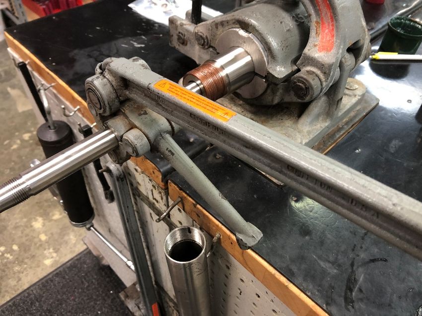
Listing of Figures

Figure 1: 1-7/8" Friction Wrench ............................................................................................................................................ 4
Figure 2: Axial Isolator Location in MWD String .................................................................................................................... 4
Figure 3: J-28348-64 Axial Isolator - Exploded View ............................................................................................................. 7
Figure 4: J-28348-64 Axial Isolator External Joints ............................................................................................................... 8
Figure 5: J-28348-64 Axial Isolator Internal Joints................................................................................................................. 8
Figure 6: J-28348-64 Shoulder-to-Shoulder Length .............................................................................................................. 9
Figure 7: Standard Tools ........................................................................................................................................................ 9
Figure 8: FAS-60530 T-Seal Funnel .................................................................................................................................... 10
Figure 9: FAS-61430 Torque Wrench Adapter .................................................................................................................... 10
Figure 10: Sealing Sub Section View ................................................................................................................................... 22
Figure 11: Sealing Sub Exploded View ................................................................................................................................ 22

UM1004 | MRO-00011             05/21 Rev.0       DCO-016875
1.0      INTRODUCTION
The patented LORD J-28348-64 MWD Tool Axial Isolator is designed for service in air, foam, or mud drilling operations.
Its use and maintenance requirements are summarized in this document.

2.0     FUNCTION
The LORD J-28348-64 MWD Tool Axial Isolator (herein referred to as the Isolator) is designed to protect the sensitive
electronics in an MWD string by isolating these components from broad frequency vibrations. The isolator will also
attenuate shock inputs.

3.0     ASSEMBLY INTO MWD/LWD TOOL STRING

3.1       Mechanical
The Isolator has been designed to be assembled and disassembled to MWD String with 1-7/8 inch (1.875 inch) diameter
friction wrenches and/or friction vise.

                                             Figure 1: 1-7/8" Friction Wrench

3.2     Pressure Conduit
The Isolator is designed to be used as fluid conduit for use with a pulser.

3.3     Location in MWD String
The Isolator has been designed to support the MWD string and be located directly between the pulser driver and lower
end.

                                    Figure 2: Axial Isolator Location in MWD String

UM1004 | MRO-00011   05/21 Rev.0   DCO-016875                                                                       4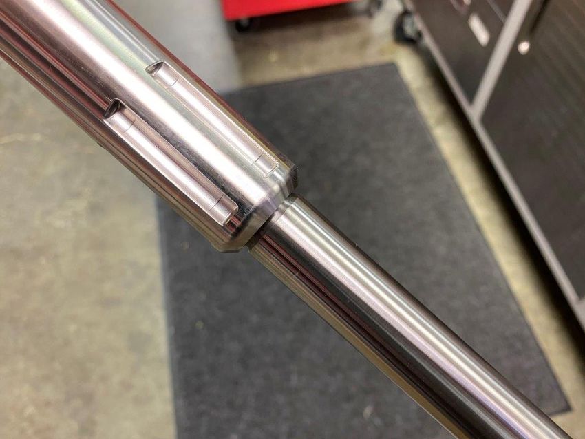
4.0       OPERATING PARAMETERS

4.1     Maximum Operating Conditions
The Isolator was designed for the operating conditions shown in Table 1.
                                               Table 1: Maximum Operating Conditions
                                               Temperature      350°F maximum
                                               Pressure         N/A

The Isolator can withstand temperatures of 350°F and beyond; however, extended periods of exposure to this extreme
condition should be avoided. Prolonged exposure to consistent elevated temperatures (>300°F) will accelerate the
degradation of the elastomer package, reducing the elastomer’s overall useful life. Elastomer kits rated for high
temperature use are available, please contact your Parker LORD representative for details.

The Isolator has no pressure rating limitations as it is pressure compensated with the downhole environment.

4.2     Maximum Static Loads
The maximum loads for the Isolator are shown in Table 2. Note that the recommended assembly torque is 250 ft-lb, well
below the maximum torque.
                                                    Table 2: Maximum Static Loads
                                          Maximum Torque                400 ft-lb
                                          Axial Load (Fishing Load)     5,000 lb

4.3      Explosive Decompression
The Isolator was not designed to function following an explosive decompression event. If any such event should occur,
the Isolator should be removed from use, disassembled, assessed for damage, and any damaged components replaced.

5.0     PARTS LIST
The Isolator consists of the items shown below, in Table 3. An Illustrated Parts List (IPL) is shown in Figure 3, Section 8.0.
                                                  Table 3: Axial Isolator 3.5 Parts List
 Part Number                                              Quantity           Full Item Description
 J-28348-64                                                  X               Axial Isolator
 J-28460-39                                                  1               Sealing Sub Assembly
   97725A125                                                                    Metal Sealing Washer
    Y-63700-140-1                                                               Sealing Sub, Body
    Y-63700-141-1                                                               Sealing Sub, Nut
    Y-63700-142-1                                                               Sealing Sub, Ceramic Insert
 Y-63700-134-2                                               1               Pin Catch
 Y-63700-103-1                                               1               Inner Member
 Y-63700-104-1                                               1               Outer Housing
 Y-63700-105-1                                               1               Tapered Drive Washer
 Y-63700-161-1                                               1               Anti-Rotation Sub (Female)
 Y-63700-162-1                                               1               Anti-Rotation Inner Member (Male)
 J-28460-34                                                  1               Axial Elastomer Kit
 J-28460-38***                                               0               Axial Elastomer Kit, High Temperature
 J-28460-68                                                  1               Axial Redress Kit
    Y-63700-58-1                                                                Threaded Seal Piston (TSP)
   J-28460-36                                                                   Axial T-Seal Kit (2 T-Seals)
   J-28460-66                                                                   Anti-Rotation Pin Service Kit, Long
    Y-63700-138-2                                                               Guide Band
    Y-63700-164-1                                                               Guide Band
 J-28460-73                                                  1               Thread Protector Kit
 2-127-V0709-90                                              2               O-Ring, 1.424 ID, VITON, 90 Shore
 2-125-V0709-90                                              1               O-Ring, 1.299 ID, VITON, 90 Shore
                                                             -               KOPR KOTE
                                                             -               DOW Corning 111 Lubricant
                                                             -               LOCTITE 243 -or- LOCTITE 262
*** Alternative to J-28460-34 Elastomer Kit.

UM1004 | MRO-00011        05/21 Rev.0      DCO-016875                                                                   5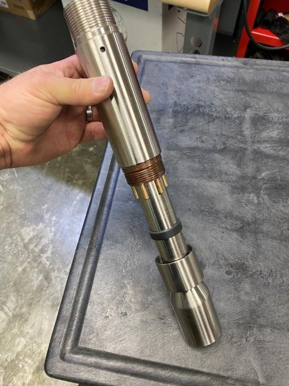
6.0     REDRESS KITS
Certain components on the Isolator are intended to be replaced on a regular basis. These Items can be purchased as part
of a basic redress kit, see Table 4. Additionally, major metals are available for purchase - refer to the Y-63700-XX Part
Numbers listed in Table 3.
                                                         Table 4: Basic Redress Kits
 Kit Number            Kit Description             Qty      Component Part Number      Description
 J-28460-34            Axial Elastomer              4       J-28348-53                 Bonded Compression Assembly
                       Kit                          2       J-28348-45                 Bonded Rebound Assembly
 J-28460-68            Axial Redress                1       J-28460-36                 Axial T-Seal Kit
                       Kit                          1       Y-63700-58-1               Threaded Seal Piston
                                                    1       J-28460-66                 Anti-Rotation Pin Service Kit, Long
                                                    1       Y-63700-138-2              Guide Band
                                                    1       Y-63700-164-1              Guide Band
 J-28460-36            Axial T-Seal Kit             2       N031B085TP009              T-Seal – HNBR, Peek
 J-28460-66            Anti-Rotation                6       Y-63700-165-1              Anti-Rotation Pin
                       Pin Service Kit,
                       Long

7.0     RECOMMENDED SERVICE KIT STOCK
Parker LORD recommends that certain service kit items be put in stock by the users of the Isolator to facilitate quick repair
or replacement of wear items. This section will detail the recommended kits and quantities that should be kept on hand.

Quantities of each kit are given per number of Isolators in service (see Table 5). For example, for each Isolator in service,
five (5) Redress Kits are recommended to be kept in stock. For some lower wear items, a single kit can support several
Isolators.
                                                      Table 5: Suggested Stock
        Part Number                            Short Description                              Suggested Stock
                                                                                   Quantity        per Axial Isolator(s)
        J-28460-34**                           Axial Elastomer Kit                   1                       1
        J-28460-68*                            Axial Redress Kit                     5                       1
        J-28460-36                             Axial T-Seal Kit                      5                       1
        Y-63700-103-1                          Inner Member                          1                       2
        Y-63700-161-1**                        Anti-Rotation Sub                     1                       2
        Y-63700-162-1**                        Anti-Rotation Inner Member            1                       2
        **Alternative versions could be stocked in place.

UM1004 | MRO-00011      05/21 Rev.0     DCO-016875                                                                           6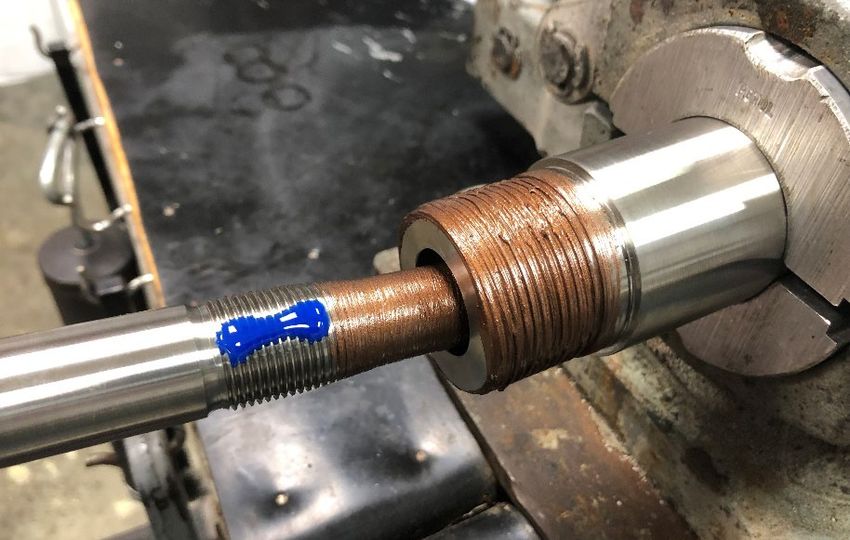
8.0     ILLUSTRATED PARTS LIST (IPL)

                                   Figure 3: J-28348-64 Axial Isolator - Exploded View

UM1004 | MRO-00011   05/21 Rev.0   DCO-016875                                            7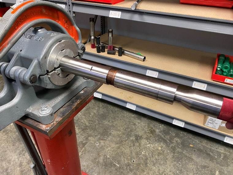
Joint A                                                                 Joint B

                                 Figure 4: J-28348-64 Axial Isolator External Joints                       Joint C
                        Joint D                                        Joint E

                                                                                                               Joint F

                                        Figure 5: J-28348-64 Axial Isolator Internal Joints

9.0     FIELD CHECKS AND MAINTENANCE

9.1      Service Intervals
Maintenance and replacement of key wear items is critical to maintaining performance of the Isolator. Recommended
service intervals for the Isolator components are shown in Table 8. See section 11.4 for Sealing Sub Assembly (J-28460-
39) repair and maintenance.
                                           Table 6:     Thread Lubricants & Locker/Sealant
                                          Joint         Lubricant/Thread Locker/Thread Sealant
                                           A            KOPR KOTE
                                           B            KOPR KOTE
                                           C            KOPR KOTE
                                           D            LOCTITE 263
                                           E            LOCTITE 243
                                           F            LOCTITE 243

                                                      Table 7: Installation Torque
                                                   Joint      Installation Torque
                                                    A         350 ft-lb*
                                                    B         350 ft-lb*
                                                    C         350 ft-lb*
                                                    D         Hand Tight
                                                    E         Hand Tight
                                                    F         100 ft-lb
         *Installation torque is intended to be typical installation torque used on entire MWD Tool. Install using established best practices.

                                                   Table 8: Service Intervals
          Service Level                Frequency                          Section                                    Page
          Level I                      Every run                          11.1.1                                     14
          Level II                     Upon Elastomer Replacement         11.1.2                                     14
                                       based on OAL
                       Level I Service should be performed regularly and incorporated into a regular maintenance schedule.
                           *Level II Service should be performed as needed based on inspection criteria in Section 9.2.

UM1004 | MRO-00011     05/21 Rev.0      DCO-016875                                                                                               8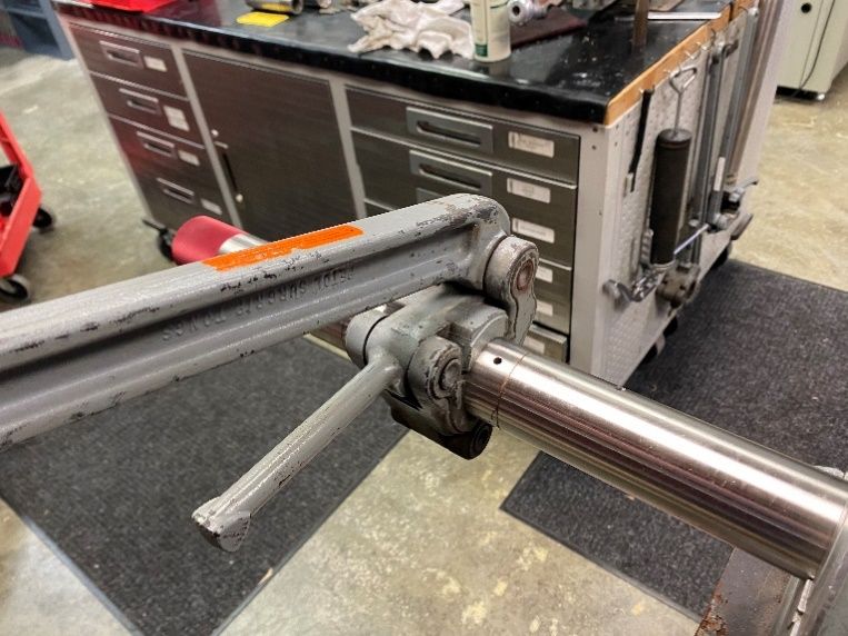
9.2     Overall Length (OAL) Inspection [Shoulder-to-Shoulder]
The nominal starting length of the Isolator is 36 ± 1/16 inches long when measured shoulder-to-shoulder as shown in
Figure 6. Between runs, the length can be checked using the below method. When the OAL falls near or below the
minimum, the Isolator requires a full elastomer replacement, Level II Service.
                                          Table 9: OAL Shoulder-to-Shoulder
                                     Nominal             36 inches
                                     Minimum             35 inches

The anti-rotation feature should also be checked before the Isolator is run below the rotary table. To do so, attempt to
manually rotate the Isolator. If the part rotates, tear down the Isolator and ensure pins are installed and are in working
condition.

                                                Shoulder-to-Shoulder Length
                                   Figure 6: J-28348-64 Shoulder-to-Shoulder Length

10.0    SERVICE TOOLS

10.1    Standard Tools
The Isolator was designed to be assembled and disassembled using primarily standard tools.

Pipe wrenches shall NOT be used during assembly or disassembly of the Isolator. Additionally, torches or similar heat
generating devices shall NOT be used in an attempt to loosen joints.
                                           Table 10: Required Standard Tools
                 Size                     Tool Description                                Service Level
                 1-7/8 inch               Friction Vise                                   Level I
                 1-7/8 inch               Friction Wrench                                 Level I
                 7/8 inch                 Friction Wrench                                 Level II
                 7/8 inch                 Locking Pliers                                  Level II
                 1-1/2 inch               Open-End Wrench/ Adjustable Wrench              Level II

                                                 Figure 7: Standard Tools

UM1004 | MRO-00011   05/21 Rev.0   DCO-016875                                                                            9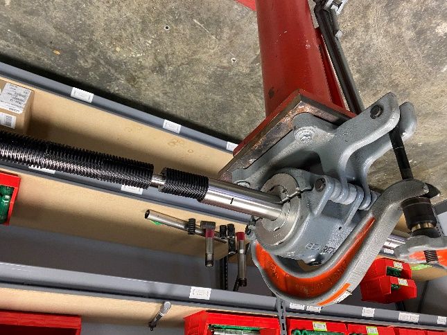
10.2    Special Tools
Specialized tools are used to assist in the assembly of the Isolator and are provided directly from LORD. These tools are
shown in Table 11.
                                                Table 11: Special Tools
                Tool Number              Tool Description                        Service Level
                FAS-60530                T-Seal Funnel                           Level I, Level II
                FAS-61430                Torque Wrench Adapter                   Special Cases

FAS-60530 is a funnel used to install the T-Seals.

                                          Figure 8: FAS-60530 T-Seal Funnel

FAS-61430 is a torque wrench adapter used to install and/or remove the nut from the Sealing Sub Assembly, which is
only required if the ceramic insert requires replacing.

                                     Figure 9: FAS-61430 Torque Wrench Adapter

11.0    SERVICE INSTRUCTIONS
This section provides detailed instructions on assembling, disassembling, and servicing the Isolator. Included are
photographs depicting these processes.

11.1    Service Levels
11.1.1 Level I Service
Level I Service includes:
• Replacing O-Rings on the Sealing Sub Assembly (-125 and -127 O-Rings)
• Axial Redress Kit [J-28460-68]
   o Replacing the two (2) T-Seals [J-28460-36]
   o Replacing the Threaded Seal Piston (TSP) [Y-63700-58-1]
   o Replace the six (6) Dowel Pins [J-28460-66]
   o Replacing Guide Band, PEEK [Y-63700-138-2]
   o Replacing Guide Band, PEEK [Y-63700-164-1]
Purchase Axial Redress Kit [J-28460-68] to perform Level I Service.
11.1.2 Level II Service
Level II Service includes:
• Replacing O-Rings on the Sealing Sub Assembly (-125 and -127 O-Rings)
• Axial Redress Kit [J-28460-68]
   o Replacing the two (2) T-Seals [J-28460-36]
   o Replacing the Threaded Seal Piston (TSP) [Y-63700-58-1]
   o Replace the six (6) Dowel Pins [J-28460-66]
   o Replacing Guide Band, PEEK [Y-63700-138-2]
   o Replacing Guide Band, PEEK [Y-63700-164-1]
• Axial Elastomer Kit [J-28460-34]
   o Replace the Elastomer Package (four (4) compression stacks [J-28348-53] and two (2) rebound stacks [J-28348-
      45])
UM1004 | MRO-00011   05/21 Rev.0   DCO-016875                                                                        10
• Replace Items as required due to wear/wash Purchase Axial Elastomer Kit [J-28460-34], and Axial Redress Kit [J-28460-68] to perform Level II Service. 11.2 Disassembly Procedure 1. Secure Outer Housing (Y-63700-104-1) in vise. 2. Remove Sealing Sub Assembly (J-28460-39) from Outer Housing [Joint A]. 3. Loosen, but do not fully remove, Pin Catch (Y-63700-134-2) [Joint C]. 4. Break Anti-Rotation Sub (ARS) (Y-63700-161-1) from Outer Housing (Y-63700-104-1) and remove [Joint B]. UM1004 | MRO-00011 05/21 Rev.0 DCO-016875 11
5.   Place Anti-Rotation Sub (Y-63700-161-1) in a friction vise (or utilize a friction tong) and remove Threaded Seal
     Piston (TSP) (Y-63700-58-1) using locking pliers [Joint D].

6.   Remove (4) Elastomer Bonded Compression Stacks (J-28348-53).

7.   Utilize open end wrench to remove Tapered Drive Washer (Y-63700-105-1) [Joint E].

8.   Remove (2) Elastomer Bonded Rebound Stacks (J-28348-45).

UM1004 | MRO-00011   05/21 Rev.0   DCO-016875                                                                           12
9. Utilize 7/8" friction wrench to remove Inner Member (Y-63700-103-1) from Anti-Rotation Sub [Joint F]. 10. Remove Pin Catch (Y-63700-134-2), Guide Band (Y-63700-138-2) and (6) Pins (Y-63700-165-1) [Joint C]. UM1004 | MRO-00011 05/21 Rev.0 DCO-016875 13
11.3      Assembly

1. Install Pin Catch (Y-63700-134-2) and Guide Band (Y-63700-138-2) over Anti-Rotation Inner Member (Y-63700-162-1).

2.     Apply grease to the (6) pin grooves and install the (6) pins (Y-63700-165-1).

UM1004 | MRO-00011     05/21 Rev.0   DCO-016875                                                               14
3.   Slide Anti-Rotation Sub (Y-63700-161-1) over Anti-Rotation Inner Member (Y-63700-162-1). Apply Kopr Kote on
     Threads and Hand-tighten Pin Catch (Y-63700-134-2) over Guide Band (Y-63700-138-2) [Joint C].

4.   Apply LOCTITE 243 to Inner Member (Y-63700-103-1).

UM1004 | MRO-00011   05/21 Rev.0   DCO-016875                                                                 15
5. Install the Anti-Rotation Sub (Y-63700-161-1) in Friction Vise. Install the Inner Member (Y-63700-103-1) into the Anti-
Rotation Inner Member (Y-63700-162-1) [Joint F] through the Anti-Rotation Sub (Y-63700-161-1). Kopr-Kote may be
added to tip of Inner Member shaft (Y-63700-103-1) to lubricate tapered shoulder for assembly.
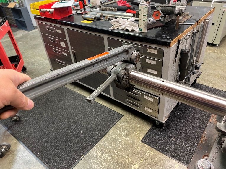
6. Use 7/8" friction wrench, securing Inner Member (Y-63700-103-1) to Anti-Rotation Inner Member (Y-63700-162-1)
and torque to 100 ft-lb. [Joint F].
UM1004 | MRO-00011 05/21 Rev.0 DCO-016875 167. [Optional] Joint F can be verified to be fully seated by disconnecting the Pin Catch (Y-63700-134-2) from the Anti-
Rotation Sub (Y-63700-161-1), fully exposing Joint F. Confirm the undercut/thread relief on Inner Member (Y-63700-
103-1) is 50% exposed.
8. Install (2) Bonded Rebound Stacks (J-28348-45).
9. Apply LOCTITE 243 on center thread of Inner Member (Y-63700-103-1).
UM1004 | MRO-00011 05/21 Rev.0 DCO-016875 1710. Install Tapered Drive Washer (Y-63700-105-1) hand tight [Joint E].
Ensure the undercut/thread relief on Inner Member is 50% exposed.
11. Install (4) Bonded Compression Stacks (J-28348-53).
12. Apply LOCTITE 243 or LOCTITE 262 to Threaded Seal Piston (TSP) (Y-63700-58-1).
13. Hand tighten TSP to Inner Member (Y-63700-103-1) [Joint D].
UM1004 | MRO-00011 05/21 Rev.0 DCO-016875 1814. Use FAS-60530 (can be obtained from LORD) to install (2) T-Seals. 15. Secure Outer Housing (Y-63700-104-1) in vise. 16. Insert Assembly into Outer Housing. 17. Torque Pin Catch (Y-63700-134-2) to Anti-Rotation Sub (Y-63700-161-1) with 350 ft-lb [Joint C]. UM1004 | MRO-00011 05/21 Rev.0 DCO-016875 19
18. Torque Anti-Rotation Sub (Y-63700-161-1) to Outer Housing (Y-63700-104-1) with 350 ft-lb [Joint B].

19. Apply Dow Corning 111 to TSP, thoroughly covering T-Seals (J-28460-36).

20. Slide TSP with T-Seals into Sealing Sub Body (Y-63700-140-1). Install Sealing Sub Assembly (J-28460-39) to Outer
    Housing and torque to 350 ft-lb (Y-63700-104-1) [Joint A].
    It is critical to apply ample thread lubricant per Table 6 to this joint to avoid galling as pre-compression is applied to
    the elastomer section.

21. Install O-Rings onto Sealing Sub Assembly (J-28460-39) and install Thread Protectors.

UM1004 | MRO-00011   05/21 Rev.0   DCO-016875                                                                           20
11.4 J-28460-39 Sealing Sub Assembly/Disassembly If replacement of the ceramic insert due to damage, or the sealing sub body due to wash or wear is required LORD can disassemble and re-assemble the components if the customer purchases required components. 11.4.1 J-28460-39 Disassembly Disassembly can be accomplished with the FAS-61430, friction vise, arbor press, 1" dowel rod, and torch. The torch is required to break down the LOCTITE 243 as well as to swell the body to aid in disassembly. 11.4.2 J-28460-39 Assembly Assembly requires a friction vise, FAS-61430, LOCTITE 243, a fresh 97725A125 Metal Sealing Washer, and torque wrench with a ½" drive. Apply LOCTITE 243 to OD of Sealing Sub, Ceramic Insert (Y-63700-142-1) and insert it into the body. Insert the Metal Sealing Washer (97725A125), apply LOCTITE 243 to the Sealing Sub, Nut (Y-63700-141-1) and install to a torque of 100 ft-lbs. UM1004 | MRO-00011 05/21 Rev.0 DCO-016875 21
Figure 10. Sealing Sub Section View

                                                                    Figure 11. Sealing Sub Exploded View

Values stated in this document represent typical values as not all tests are run on each lot of material produced. For formalized product specifications for specific product end uses, contact the Customer
Support Center.
Information provided herein is based upon tests believed to be reliable. In as much as Parker LORD has no control over the manner in which others may use this information, it does not guarantee the
results to be obtained. In addition, Parker LORD does not guarantee the performance of the product or the results obtained from the use of the product or this information where the product has been
repackaged by any third party, including but not limited to any product end-user. Nor does the company make any express or implied warranty of merchantability or fitness for a particular purpose
concerning the effects or results of such use.
WARNING — USER RESPONSIBILITY. FAILURE OR IMPROPER SELECTION OR IMPROPER USE OF THE PRODUCTS DESCRIBED HEREIN OR RELATED ITEMS CAN CAUSE DEATH,
PERSONAL INJURY AND PROPERTY DAMAGE.
This document and other information from Parker-Hannifin Corporation, its subsidiaries and authorized distributors provide product or system options for further investigation by users having technical
expertise.
The user, through its own analysis and testing, is solely responsible for making the final selection of the system and components and assuring that all performance, endurance, maintenance, safety and
warning requirements of the application are met. The user must analyze all aspects of the application, follow applicable industry standards, and follow the information concerning the product in the current
product catalog and in any other materials provided from Parker or its subsidiaries or authorized distributors.
To the extent that Parker or its subsidiaries or authorized distributors provide component or system options based upon data or specifications provided by the user, the user is responsible for determining
that such data and specifications are suitable and sufficient for all applications and reasonably foreseeable uses of the components or systems.

Parker LORD
Engineered Materials Group
Oil & Gas Engineering
111 LORD Drive
Cary, NC 27511-7923
USA
phone +1 855 796 1595
OilandGas@lord.com
www.lord.com/OilandGas

UM1004 | MRO-00011                 05/21 Rev.0           DCO-016875                                                                                                                                 22
You can also read