DESIGN OF POWER WEEDER FOR LOW LAND PADDY CULTIVATION
←
→
Page content transcription
If your browser does not render page correctly, please read the page content below
468

        DESIGN OF POWER WEEDER FOR LOW LAND PADDY CULTIVATION

     Ratnaweera A.C1 , Rajapakse N. N.2, Ranasinghe C. J.1, Thennakoon T.M.S.1, Kumara.R.S.2,
                                Balasooriya C. P3, Bandara M. A3
              1
                  Senior Lecturer: Department of Mechanical Engineering, Faculty of Engineering,
                                        University of Peradeniya, Sri Lanka
                                     1
                                       E-mail: asangar.ratnaweera@gmail.com
                    2
                        Graduates, Department of Mechanical Engineering, Faculty of Engineering,
                                           University of Peradeniya, Sri Lanka
                           2
                             E-mail: rajapaksenne@yahoo.com. 2Telephone: +94-773979639
                                  3
                                      Department of Agriculture, Peradeniya, Sri Lanka.

ABSTRACT — Lack of man power has been identified as one of the major problems for the sustainability of
the Sri Lankan paddy industry. Hence transplanters and seeders were well developed as a step for
mechanization. However, weeding method is still not well developed up to mechanization. Therefore, our main
objective is to design and fabrication of a power weeder. Weeding ability will be optimized by weeding three
rows simultaneously. The machine is designed to use in the fields, cultivated by using mechanized seeder or
mechanized transplanter introduced by Farm Machinery Research Centre (FMRC), Sri Lanka.
The double-action weeding drums will be driven by a small 1.3 kW gasoline engine, that can enable removal of
weeds, while facilitating the forward motion of the machine. In addition, the conical shaped weeding drums will
be designed to loose-up soil without harming the paddy. Totally six drums will be used, in such a way that rear
three drums have high angular velocity with respect to the front drums.
A novel maneuvering method for row changing when the machine is in paddy fields also introduced in the
design. More than 5-fold improvement of weeding efficiency in terms of weeding time is expected in this
design. Further, a significant improvement of weeding quality is also expected in this design.

Keywords – Weeds, Paddy cultivation, Manual weeders, Mechanized weeders, Double action-weeding drums

ABBREVIATIONS
Fos                                       – Factor of safety

    1. INTRODUCTION

Weeds are a major problem in paddy cultivation. Herbicides are usually used for weed controlling
despite the fact that herbicides have many negative effects due to environmental contamination.
It has been understood that mechanized weeding significantly improves weeding efficiency as well as
the quality of weeding. However, it may consume non-renewable petroleum for operations.
Cono-weeder, which is mechanized weeding (manual) method, capable of weeding about 0.18 ha/day.
However, operational difficulties and slow weeding rate have been identified as major drawbacks of
this weeder, particularly in large-scale cultivation.
The specifications of a paddy field, which is cultivated by using a mechanized seeder, are as
follows.(ground requirement for power weeder)
        The space between each row of paddy is about 8 inches.
        The spaces between two paddy plants are 2-3 inches.

                  International Conference on Sustainable Built Environment (ICSBE-2010)
                                        Kandy, 13-14 December 2010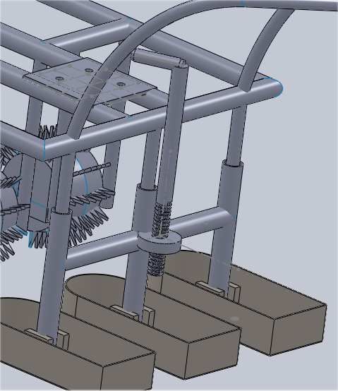
469
8” Paddy plants Weeding area
* * * * * *
* 1: Top
Figure * view*of a paddy
* field * *
* * * * * *
* * * * * *
* * * * * *
Paddy raw The boundary (bund)
The machine is to be designed to remove weeds while travelling along the weeding area of the field as
shown in Figure 1. Simultaneous removal of weeds in several weeding areas is a key requirement for
efficient operation. Further, a mechanism is needed to move the machine between weeding areas
without damaging paddy plants. The major mechanical engineering considerations in the design are:
Driving mechanism, Weeding mechanism, Turning and row changing mechanism, Power
transmission, Floating mechanism.
2. OBJECTIVES AND METHADOLOGY
The main objective is to design and fabrication of a power weeder, while minimum damages done to
paddy plants, cost effectiveness, easy manuvelling, low weight, fabricationby using freely available
components and easy maintenance are main features of this design. The following methodology was
used:
Development of the concept
No or minimum damage to the paddy
Easy maneuvering on wet fields
Dynamic analysis and mechanical design
Kinematic analysis
Power transmission and drive systems design
Design of mechanical components
Assembly of components
Fabrication of components
Field testing and improvements
The cost analysis
3. DEVELOPMENT OF THE CONCEPT
3.1. CHAIN DRIVEN SYSTEM
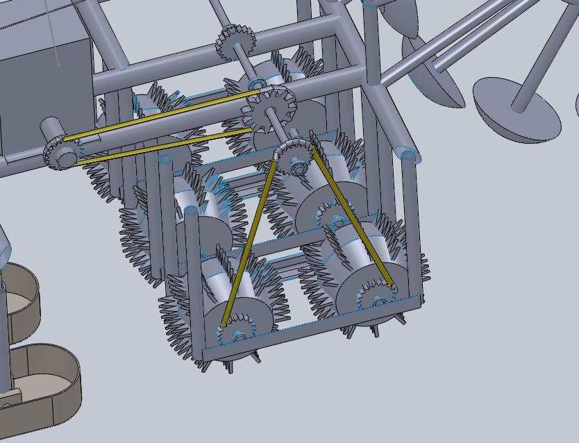
The weeding drums are driven by a chain drive arrangement as shown in Figure 2. Accordingly
specially designed double-acting weeding drums are proposed in the design to remove weeds while
providing the necessary traction to move the machine forward. Rear group of weeding drums rotate
faster than the front weeding drums to provide better shearing.
International Conference on Sustainable Built Environment (ICSBE-2010)
Kandy, 13-14 December 2010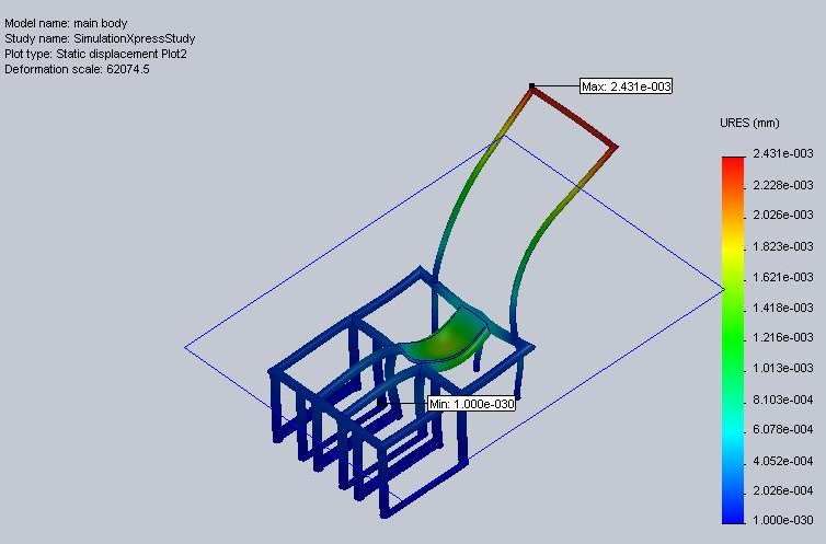
470

                Intermediate
                shaft

                                                                              Chain drives
                                                                              arrangement.

                                        Group of rear        Group of front
                                        weeding drums        weeding drums

         Figure 2: Arrangement of the weeding drums

  3.2. DEFERENTIAL SPEED OF WEEDING DRUMS

Two weeding drums which rotate at a deferential speed are suggested for each row. As shown in
Figure 2, the drums at the rear are set to rotate faster than the drums at the front by using different
sprockets. This design would enhance the shearing process due to the miss-match of linear speed of
the two drums at the ground level. Further, it helps to push the weeds already removed under the mud
to avoid any possible re-growth.

  3.3. SHAPE OF THE WEEDING DRUMS

The weeding drums are expected to perform two activities simultaneously: driving the machine
forward and weeding. As shown in Figure 3, helical shaped teeth made on conical shaped drums are
proposed for the weeding wheel. The conical shape helps to push mud to the roots of the paddy plants
as it rotates which enhances the growth of the paddy plants. On the other hand, helical shaped teeth
help to provide the shearing effect required for weeding and traction force required for the forward
motion.

            Conical shape                                                     Helical teeth

Figure 3: The weeding draum

3.4. NUMBER OF ROWS TO BE WEEDED SIMULTANEOUSLY
It has been observed that if an odd number of rows are to be weeded simultaneously the maneuvering
is easy as the operator cas easly walk in the middle raw. Therefore, it is decided to design the
machine to weed three paddy rows simultaneously at a single operation. This is schematically shown
in Figure 4.

              International Conference on Sustainable Built Environment (ICSBE-2010)
                                    Kandy, 13-14 December 2010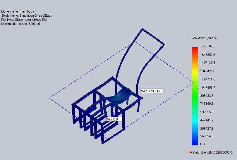
471

                                         Raw changing
               Raw changing                                                    Weeding area
               mechanism            *        *         *      *         *        *
            Front weeding           *        *         *      *         *        *
            drums                   *        *         *      *         *        *
            Rear weeding
                                    *        *         *      *         *        *
            drums
                                    *        *         *      *         *        *
                                                                  Man

                               Figure 4. Top view of the Operational behavior in the field.

  3.5. TURNING AND ROW CHANGING MECHANISM OF THE MACHINE

In order to ensure continuous weeding, it is necessary to change the machine from one set of rows to
another set without damaging the paddy plants. Thus an effective mechanism inspired by the human
leg movement is invented. The initial configuration is shown in Figure 5.
                                                 Pad
                                                 s

Figure 5: Initial turning and raw changing mechanism          Figure 6: Developed mechanism

The initial design consists of four floater pads as shown in Figure 5. Each pad is pin jointed to a steel
rod which is connected to the central hub using a bearing so that the rod is free to turn about its own
axis. As a result each pad is free to rotate about two mutually perpendicular directions. This turning
mechanism is fixed at the front of the machine.
The mechanism is fabricated and tested in paddy fields under different ground conditions. An
acceptable operating characteristics were observed. However, several issues with regards to the
durability and maintenance have been recognized as bearings and pin joints can easily get damaged in
muddy conditions. Therefore, as shown in Figure 6, hemispherical floating pads rigidly connected to
the central hub using steel rods are proposed in the final design.

  3.6. FLOATING MECHANISM

The floating mechanism is another important part of the machine, as it helps the machine to float in
muddy conditions without sinking. The floaters reduce the ground reaction due to buoyancy effect. In
the present study three adjustable mechanical floaters are considered to control the depth of shearing
as required in different ground conditions.
The height adjustment has been achieved by using a simple arrangement with the aid of a screw as
shown in Figure 7.

              International Conference on Sustainable Built Environment (ICSBE-2010)
                                    Kandy, 13-14 December 2010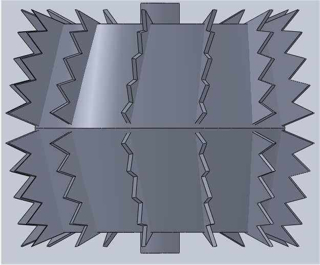
472

       Screw

           Nut                                                                       Floater adjusting arm

                                                         Figure 7: The floating mechanism

4. THEORY AND CALCULATIONS

4.1. POWER REQUIREMENT OF THE ENGINE.[3]
Maximum Shearing area for one blade                                            = 4x10⁻³ m2

(Assuming three blades are shear the soil at same time)

Effective shearing area for one weeding drum                                   = 12*10-3 m2

(Assume only three blades are done the effective shearing)

Shear stress of the soil (APPENDIX 2)                                          = 5*103 Nm-2

Effective force on the weeding drum (area*shear stress)                        = 120 N. (FOS = 2)

The average speed of the drum (design value)                                   =1.3 ms-1(14.1rad /s)

Average radius of the weeding drum                                             =8*10-2 m

Average power requirement for one weeding drum (torque *speed)                 =120*8*10-2*14.1

                                                                               =135 W

Total power requirement for all weeding drums                                  =810 W( 135*6)

  4.1.1. SPEED REDUCTION
The comfortable working speed in the paddy fields                              = 2.5 km/h(0.7 ms-1 ) .[4]
The detailed schematic diagram is shown in Figure 4.

                                  A

       Forward

                            B            C
                                               A– Driving wheel which connect to the intermediate shaft
                                               B & C–Driven wheels which connect to the weeding drums

The speed of engine shaft / speed of intermediate shaft              = 270 / 135
                                                                     =2/1

                 International Conference on Sustainable Built Environment (ICSBE-2010)
                                       Kandy, 13-14 December 2010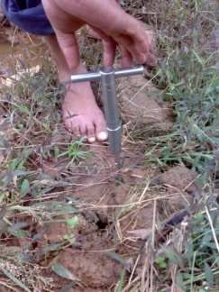
473

5. RESULTS.
Table 2: The engine selection
                      Total     power safety factor          The    estimated
                      requirement/kW                         power/kW
                      0.81            1.5                    1.2

Table 3: Design of chain drives
                     Rated power/kW       safety factor      Design
                                                             power/kW
                      1.3                 1.5                1.95

Table 4: Speeds of each drum
Speed of intermediate drum,NA / Speed of front            drum,Nb/
                                                                     Speed of rear drum,Nc/ rev/min
rev/min                         rev/min
135                             121rev/min                           148 rev/min
Note : Nb < Nc

APPENDIX 1

Figure 8: Static deflection of the main body frame

Hence main body frame was not statically deflected as the test shown in above figure 8. The test was
done by using solid works.

              International Conference on Sustainable Built Environment (ICSBE-2010)
                                    Kandy, 13-14 December 2010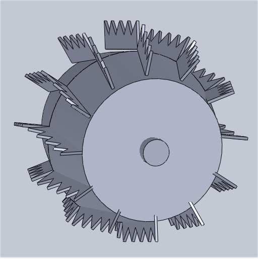
474

Figure 9: Static nodal stress of the main body frame
Hence there was no excessive static nodal stresses developed in the main body as the test shown in
above figure 9. The test was done by using solidworks

        APPENDIX 2

        VANE SHEAR TESTER

Vane shear test was done to investigate the shear stresses of the soil of paddy fields.

                           Figure 10: Vane shear testing

RESULTS
     Shear stress near bund                                = 15 MPa
     Shear in the middle of the paddy field                = 5 MPa
     Average shear stress                                  = 10 MPa
DISCUSSIONS
    •    The novel raw changing mechanism would be helpful for operating the machine by single
         person without destroying paddies.
    •    According to Figure 8 and 9 the structure would safe for static loads.

              International Conference on Sustainable Built Environment (ICSBE-2010)
                                    Kandy, 13-14 December 2010
475

5. CONCLUSION
    •    Cost effective method for weed controlling
    •    Attracting the young generation for paddy industry because of mechanization.
    •    Well improved, unique raw changing mechanism would increase the effectiveness of the
         power weeder.
    •    A novel double action weeding drum is introduced in this design to facilitate the effective
         weeding while providing the necessary traction for the forward motion of the machine.
    •     Helical shaped teeth is formed in the weeding drums to enhance the shearing effect for
         weeding while loosing up the soil.
    •    The weeding drum is formed into conical shape to push the mud towards the paddy plants to
         ensure the proper growth.
    •    Two drums operate at differential speed is used to further improve the shearing process.
    •    Three sets of such drums were fixed in parallel to remove weeds in three paddy rows
         simultaneously

REFERENCES
    1.   A Tajudding/ R Karunanithi/ K R Swaminathan./ Design, development and testing of and engine
         operated blade harrow for weeding/ Indian journal of agricultural engineering, vol 1, no 2, 1991
    2.   A Tajuddin./ Mechanising Indian Agriculture. /Kisan World, vol 31, no 6, 2004
    3.   R.S. khurmi/ J.K. gupta/ A Textbook of Machine Design/ Multicolor Edition
    4.   www.sri agricultural machineries.com
NAMES AND ADRESSES OF AUTHERS
1. Corresponding author: Rajapakse N.N
Graduate, Department of Mechanical Engineering, Faculty of Engineering, University of Peradeniya,
Sri Lanka.
Telephone:       Mobile :         +94773979639 Email: rajapaksenne@yahoo.com.
                 Residence :     +94472254478

2. Authors: Thennakoon. T.M.S
Graduate, Department of Mechanical Engineering, Faculty of Engineering, University of Peradeniya,
Sri Lanka.
Telephone: +94776115847.                                    Email : thennakoonsuranjith@yahoo.com.

3. Ranasinghe S.N.B.M.C.J
Graduate, Department of Mechanical Engineering, Faculty of Engineering, University of Peradeniya,
Sri Lanka.
Telephone: +94718159336.                                    Email: chamilaranasinghe@gmail.com.

4. Kumara. G.R.R.S
Graduate, Department of Mechanical Engineering, Faculty of Engineering, University of Peradeniya,
Sri Lanka.
Telephone: +94716670514.                                    Email: ravindraruwan@gmail.com

5. Dr. A.C. Ratnaweera
Senior lecturer, Department of Mechanical Engineering, Faculty of Engineering, University of Peradeniya, Sri
Lanka.
Telephone: +94812393627                                    E-mail: asangar.ratnaweera@gmail.com

6. Bandara M. A
Chief Engineer, Department of Agriculture, Peradeniya.
Telephone: +94 812388155, +94 714133403

               International Conference on Sustainable Built Environment (ICSBE-2010)
                                     Kandy, 13-14 December 2010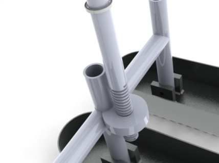
You can also read