Designing and Prototyping for Conservation and Effective Utilization of Waste Heat from Air Conditioner
←
→
Page content transcription
If your browser does not render page correctly, please read the page content below

IOP Conference Series: Materials Science and Engineering

PAPER • OPEN ACCESS

Designing and Prototyping for Conservation and Effective Utilization of
Waste Heat from Air Conditioner
To cite this article: Amit Choudhari et al 2021 IOP Conf. Ser.: Mater. Sci. Eng. 1104 012007

View the article online for updates and enhancements.

 This content was downloaded from IP address 46.4.80.155 on 30/07/2021 at 14:39
ICOTRIME 2020 IOP Publishing
IOP Conf. Series: Materials Science and Engineering 1104 (2021) 012007 doi:10.1088/1757-899X/1104/1/012007

 Designing and Prototyping for Conservation and Effective
 Utilization of Waste Heat from Air Conditioner

 Amit Choudhari1 Aditya Rane2 Shamir Talkar3 Pawan Rayar4 Dhananjay
 Shukla5
 1
 Design Engineer, Worley, Mumbai, India
 2
 Project Engineer, Radcorps fire and safety Pvt Ltd, Mumbai, India
 3
 Design Engineer, Arkk Consulting, Mumbai, India
 4
 Professor, Dwarkadas J Sanghvi College of Engineering, Mumbai, India
 5
 Professor, Dwarkadas J Sanghvi College of Engineering, Mumbai, India

 Email:- amitchoudhari.r@gmail.com

 Abstract. Nowadays Energy is becoming a crucial part of human needs and it’s essential for the
 day to day activities. We use an enormous amount of energy either from fossil fuels, electricity,
 or solar to heat the water to fulfil the need of residential or industrial sectors, and unfortunately,
 we consciously lose out a significant amount of energy in the form of heat from the condensers
 of air conditioning. Hence conservation of energy and its effective utilization has become
 imperative. The main objective of this research paper is to demonstrate how the waste heat which
 is dissipated from the condenser coil of a 1-ton Air conditioner is being utilized for heating the
 water and used to increase the Coefficient of Performance (COP) of the system. Therefore, by
 redesigning the condenser part of AC we would be able to appease the necessity of the heated
 water for bathing, cleaning, space heating, etc. in hostels, restaurants, for domestic and industrial
 use as a primary unit or with a hybrid water heater system.

1. Introduction
The use of air conditioners has increased significantly in the past few years including commercial as
well as residential areas. Its effect is directly on the consumption of electricity and other resources. From
an advancement perspective, especially the HVAC industry has grown incredibly well in terms of energy
consumption, compact-ness, reduction in carbon footprints, use of environment-friendly refrigerants
with a reliable and sustainable product. [1] Even though we are approaching to reach the peak in the
advancement but unfortunately every year a huge amount of energy in the form of heat from the
condenser of air conditioners is consciously released into the atmosphere in the form of waste which is
pathetic. This research paper is about the methods or techniques by which a large portion of waste heat
of air conditioner can be recovered and utilized for our day to day applications. In this research paper,
two experiments are conducted to demonstrate how the modification in some portion of the air
conditioner results in the recovery of a huge amount of heat which is otherwise gets wasted. The cost
and efficiency are the two-parameter that governs the designing of any new system or doing some
modification in the existing one by giving utmost importance to the primary function and quality.
Therefore, considering all these parameters a system is designed and prototyped. From a future
perspective, this experiment may help the researcher to rethink and design a system by which, such a
great amount of energy can be utilized for human needs.

 Content from this work may be used under the terms of the Creative Commons Attribution 3.0 licence. Any further distribution
 of this work must maintain attribution to the author(s) and the title of the work, journal citation and DOI.
Published under licence by IOP Publishing Ltd 1
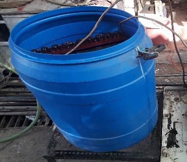
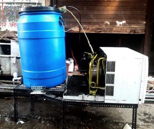
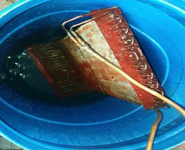
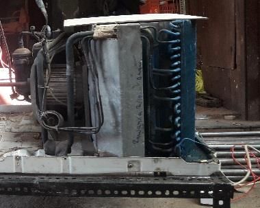
ICOTRIME 2020 IOP Publishing
IOP Conf. Series: Materials Science and Engineering 1104 (2021) 012007 doi:10.1088/1757-899X/1104/1/012007

2. Constructional Details:

Annotations used in schematic representation as figure 1 are as follows,
 a. Window Air Conditioner e. Supporting frame
 b. Condenser coil f. Water tap
 c. High density poly Ethylene (HDPE) Tank g. Temperature sensor
 d. Water Sprinkler h. External pump

 Figure 1. Schematic representation Figure 2. Constructional setup

2.1. Window Air Conditioner & it’s Condenser Coil

In this experimental setup an old window air conditioning of 1 TR capacity is used which is as shown
in figure 3. [2] In this A.C, the condenser portion is reconstructed by adding a copper coil to it which is
then placed inside the tank as shown in figure 4 to carry out the experiment.

 Figure 3. Window Air Conditioner Figure 4. Condenser coil immersed in tank

2.2. Water tank and Shower head

 Figure 5. HDPE water tank Figure 6. Shower head to sprinkling water

 2
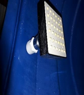
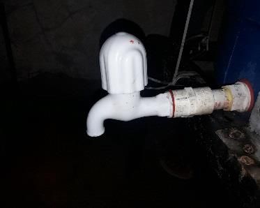
ICOTRIME 2020 IOP Publishing
IOP Conf. Series: Materials Science and Engineering 1104 (2021) 012007 doi:10.1088/1757-899X/1104/1/012007

The high-density polyethylene tank is shown in figure 5, It is used because of the cost involved in using
a metallic tank of the same size. It can withstand a temperature of 85oC without any significant change
in physical properties as its melting point is 111.90oC which is obtained from the manufacturer’s manual.
To carry out experiment a water sprinkler which is a showerhead used and connected with the tank as
shown in figure 6.

2.3. Supporting Table and Water tap: -

As the window air conditioners are bulky and 150 liters of the tank with 100 liters of water, is used for
the experiment, so to support these a robust base frame is designed and fabricated which is as shown in
figure 7. Its dimensions are 50 cm×25 cm to hold the Air conditioner and 45 cm × 20 cm to hold the
water tank & made up of mild steel. A water tap is also installed with the tank to drain out the water
from the tank which is shown in figure 8.

 Figure 7. Supporting Table Figure 8. Water tap

3. Working:
As shown in figure 2, the entire assembly is placed over the frame. For analysis purposes after the
theoretical conceptualization, it becomes imperative to validate it by using different experiments hence
we conducted two experiments. In 1st experiment, as the Air conditioning is turned on the refrigeration
cycle starts. [3] When the liquid refrigerant reaches at evaporator inlet after the expansion coil it absorbs
the heat of the system and gets converted into vapor which then passed through the compressor where
it pressurizes, and high-pressure high-temperature vapor enters into the condenser. Since the coil placed
inside the water there is a significant amount of heat released to the water and as a result, this waste heat
gets utilized for heating the water. In 2nd experiment, an external motor is used to force the water over
the coil, and with the help of a water sprinkler, it gets converted into small droplets. [4] Here convection
is taking place with air as well as the water droplets as a result more amount of heat gets released and
sub-cooling takes place. Whereas in conventional A.C there is forced convection takes place over the
coils by blowing air over it with the help of a fan.

4. Experimental Result

4.1. Sample Calculation: -

Following are the specification of the experimental setup: -
The Window A.C is 3-star rating, so the energy efficiency ratio (EER) is 2.7 [6]
Capacity of A.C = 1 TON
Usage of Water = 100 Liters
Running hours = 1 Hour
Rated Power Input = 1407 Watt
Rated Cooling Capacity = 3517 Watt
Type of Refrigerant = R-22

 3
ICOTRIME 2020 IOP Publishing
IOP Conf. Series: Materials Science and Engineering 1104 (2021) 012007 doi:10.1088/1757-899X/1104/1/012007

All the heat will be absorbed by the water inside the tank. The total amount of heat absorbed by the
water is given by the equation,
 Q = m ∗ Cp ∗ ( 1 − 2 )
Where,
T1 and T2 are Inlet and outlet temperature of the water.
In an ideal condition, the entire rejected heat will be absorbed by the water and is equal to the sum of
the power input and amount of heat absorbed from the room which is equal to cooling capacity. So, we
can write,
 1407 + 3517 = 100 ∗ 4187 ∗ ( 1 − 2 )
( 1 − 2 ) = 0.01176℃/ Sec equivalent to increase in temp. of 7 oC in 10 minutes.

4.2. Observation table

 Table 1. Increase in temperature of water observed during experiment
 Sr. No. 1 2 3 4 5 6 7
 Time (In minutes) 0 10 20 30 40 50 60
 Expected Temp. increment (oC)* 28 35 42 49 56 63 70
 o
 Observed Temp. increment ( C) 28 33.5 37.4 41 43 45.7 47.8
*Expected time is calculated in topic 4.1

Table 1 shows the result obtained from the 1st experiment. In this experiment, the condenser coil is
immersed inside the water. The amount of water used in this experiment is 100 liters in a tank having a
capacity of 150 liters. On the day of the experiment, the atmospheric temperature is 28 oC and the tank
is open to the atmosphere. [5] When the air-conditioner is turned on the temperature of the water goes
on increasing and it is recorded with the help of a digital thermometer in 10 minutes intervals. The ideal
consideration was our temperature will increase linearly as time goes on as per the calculation in topic
4.1 but when we analyzed the result, we found that as the temperature goes on increasing, for the same
period, the temperature gradient is decreasing which is as shown in figure 9.

 Temperature incremental result
 80

 60

 40

 20

 0 Expected Temp. increment (oC) Observed Temp. incremet (oC)
 0 10 20 30 40 50 60 70

 Figure 9. Comparison of expected temperature increment with experimental data

In figure 9, the blue line indicates the increment in temperature of the water, and the red line shows the
increment in temperature result obtained from 1st experiment.

In the 2nd experiment, we use a pump and a shower head to spray the water over the coil in fine droplets
which is installed just above the condenser coil inside the tank. In this case, the water is stored in a

 4
ICOTRIME 2020 IOP Publishing
IOP Conf. Series: Materials Science and Engineering 1104 (2021) 012007 doi:10.1088/1757-899X/1104/1/012007

separate tank and then at different volume flow rates, it is sprayed over the coil. The pump discharge is
2.5 lpm and the outlet temperature of the water observed is 42.8oC which is optimum. Even though the
outlet temperature of the water is lower than experiment 1 but it is the best method to recover the waste
heat from the air conditioner effectively and efficiently. A sample calculation for each experiment is
given in the below section. The amount of power consumed for running the pump is negligible in
comparison to recovering the amount of heat, so its calculation is not included.

5. Sample Calculation: -

5.1. Experimental results obtained for calculation: -

 Figure 10. Temperature (T) – Entropy (s) diagram Figure 11. Pressure (P) - Enthalpy (h) diagram

 Table 2. Enthalpy and entropy at different points as per figure 10 and figure 11

 Properties 1 2 3 4 3' 4'
 h (Enthalpy) 397.9 426.3 302.5 302.5 318.3 318.3
 s (Entropy) 1.779 1.788 1.187 1.311 1.191 1.323

Here,
ℎ1 , ℎ2 , ℎ3 , and ℎ4 = Enthalpy of refrigerant at entry of compressor, condenser, expansion device and
evaporator respectively with dismantling the coil of condenser and immersing inside the water as shown
in figure 4.
ℎ3′ and ℎ4′ = Enthalpy of refrigerant at exit of condenser and expansion device respectively without
dismantling the coil of condenser.
 (ℎ −ℎ ) (397.90−318.3)
COP of Conventional Air conditioning = 1 4′ = = 2.8028
 (ℎ2 −ℎ1 ) (426.30−397.90)

From figure 11, h4' = h4 + (h4'-h4)

 (ℎ1 −ℎ4 ) 397.90−302.5
COP of Modified Air conditioning system = ( (ℎ2 −ℎ1 )
 )=( 426.30−397.60
 ) = 3.324

The above sample result is as per experiment 2nd Experiment which shows that there is a significant rise
in COP of the system from 2.80 to 3.32 which could only be possible after modifying the condenser
assembly.

 5
ICOTRIME 2020 IOP Publishing
IOP Conf. Series: Materials Science and Engineering 1104 (2021) 012007 doi:10.1088/1757-899X/1104/1/012007

5.2. Amount of waste heat recovered:

5.2.1 In 1st experiment: -
As the result obtained from the experiment, we can say that only a certain amount of the heat rejected
from the condenser coil can be reutilized for the purpose of any specific application i.e. for heating of
residential water storage system for day to day use, for industrial purpose, etc.
As a result, the water temperature increases from 28oC to 47.8oC in a period of 1 hr. So, the total amount
of waste heat recovered in 1 hr. is,
 Q = m ∗ C ∗ Δt
 Q = 100 ∗ 4.187 ∗ (47.80 − 28) = 8290.26

5.2.2 In 2nd experiment: -

Total amount of heat recovered (Q ) in the period of 1 hr. is, (Outlet temp. is 42.8oC)
 (Q ) = m ∗ C ∗ Δt
 Q = 2.50*60*4.187*(42.8-28) = 9295.14 KJ

6. Conclusion: -
In summary, by doing modification in the existing system by keeping in mind the future obligations and
waste energy in the form of heat which is dissipated in the atmosphere from air conditioners periodically,
must be adequately utilized. Modification in condenser design not only makes it possible to use the
waste heat appropriately but also unquestionably there is a marginal increment (from 2.80 to 3.32) in
the coefficient of performance of the entire system. By this experiment, we could also be able to extract
a considerably larger amount of heat (i.e. ~ 9300 KJ ) which can be utilized for the sterilization in
hospitals and medicals, for bathing purpose in hotels, hostels and may also be used for various domestic
applications, in the restaurants, in various chemical industries for preheating the salts, ashes and different
chemical solutions as a primary or secondary heating source. In the future, it may be one of the best
source of energy at the economical rate, which must be utilized effectively for fulfilling the need of the
human being, especially when the modern conventional air conditioners will be a part of solar modules
and will use it as a primary source of power supply.

References
[1] S.C. Kaushik, M. Singh., Feasibility and Design studies for heat recovery from a refrigeration
 system with a heat exchanger, Heat Recovery Systems & CHP, Vol.15(1995)665673
[2] P. Sathiamurthi, PSS. Srinivasan “Design and Development of Waste Heat Recovery System for
 air Conditioning Unit, European Journal of Scientific. Research, Vol.54 No.1 (2011), pp.102-
 110.
[3] M. Joseph Stalin, S. Mathana Krishnan, G. Vinoth Kumar, "Efficient usage of waste heat from
 air conditioner", International journal of advances in engineering &technology, July 2012.
 ISSN: 2231-1963.
[4] Rakesh Jain, Performance Improvement of a Boiler through Waste Heat Recovery from an Air
 Conditioning Unit, international Journal of Innovative Research in Science, Engineering and
 Technology Vol. 2, Issue 2, February 2013
[5] H.I. Abu-Mulaweh, “Design and performance of a thermosiphon heat recovery system”, Applied
 Thermal Engineering, Vol.26, (2006) 471–477
[6] https://www.bijlibachao.com/air-conditioners/air-conditioner-selection-understand-tonnage-eer-
 cop-and-star-rating.html

 6
You can also read