GAH Series ATEX compliant gas analyzer system hydrogen-cooled alternators - ABB MEASUREMENT & ANALYTICS | DATA SHEET

Page created by Marc Martinez
 
CONTINUE READING
GAH Series ATEX compliant gas analyzer system hydrogen-cooled alternators - ABB MEASUREMENT & ANALYTICS | DATA SHEET
—
ABB MEASUREMENT & ANALY TICS | DATA SHEET

GAH Series
ATEX compliant gas analyzer system
hydrogen-cooled alternators
2   GAH 200 SE RIE S AT EX COMP LI ANT ANALY ZE R SYSTE M | DS/GAH-E N   RE V. A
G AH 200 S E RIE S AT EX COMP LI ANT ANALY ZE R SYSTE M | DS/GAH-E N   RE V. A                            3

—                                                                                        —
General                                                                                  Purge gas
The GAH range of instruments is designed to provide reliable                             To complete the system the GAH series also incorporates a
and accurate hydrogen purity and purge gas measurement to                                purge gas analyzer.
ensure the safe and efficient operation of hydrogen cooled
                                                                                         During commissioning and de-commissioning of a system it
turbo-generators.
                                                                                         is essential that the hydrogen is safely introduced and
                                                                                         removed from the turbo-generator.
—
                                                                                         To avoid an explosive mixture of air and hydrogen during
Hydrogen purity                                                                          commissioning, air must first be purged from the system by
Modern high capacity turbo-generators need to be cooled                                  an inert gas; carbon dioxide is in common use for this
efficiently. Hydrogen, with a thermal conductivity of about                              purpose although argon or nitrogen are gaining popularity.
seven times that of air, is in general use as the coolant.                               The hydrogen coolant is then introduced and replaces the
                                                                                         purge gas.
Any drop in hydrogen purity during operation of the machine
has two adverse effects:                                                                 To decommission the turbo-generator the purge sequence is
                                                                                         reversed.
• The first, and most important, is to compromise the safe
  operation of the generator. Accurate measurement of
  hydrogen purity is essential to provide an early warning of
  a potentially explosive mixture of hydrogen and air.
• The second is the economic impact of reduced efficiency.
  To increase plant performance and control generating cost
  per megawatt, turbine generators must perform with
  optimum efficiency. A drop in hydrogen purity causes
  additional windage losses and consequently reduces
  generator efficiency.

                                          4,500

                                          4,000
                                                                   800 MW unit

                                          3,500
                                                                   400 MW unit
                Financial loss, $US/day

                                          3,000

                                          2,500

                                          2,000

                                          1,500

                                          1,000

                                           500

                                             0
                                                  100    99       98        97         96        95       94         93      92      91
                                                                                 % hydrogen purity

Figure 1 Typical cost of decreased hydrogen purity
4                            GAH 200 SE RIE S AT EX COMP LI ANT ANALY ZE R SYSTE M | DS/GAH-E N   RE V. A

—
Katharometer
Principle of operation                                                  Zener barrier devices
The GAH range of gas analyzers utilizes thermal conductivity            Zener barrier devices are included in the display monitor
as its principle for measurement. When a constant current is            enclosure to prevent any dangerous electrical feedback from
passed through an electrical conductor surrounded by gas in             the transmitters to the hazardous area.
a chamber, the temperature rises to a point of thermal
                                                                        Power supply
equilibrium. Provided radiation, convection and
                                                                        The 4234 power supply units provide the analyzer assemblies
end‑conduction losses are minimized, the temperature of the
                                                                        with an intrinsically safe (IS), stable constant current. These
conductor depends upon the heat loss by conduction through
                                                                        power units must be installed in a ‘safe’ area but the current
the gas. The temperature attained is therefore related to the
                                                                        output from them may be transmitted to the katharometers
thermal conductivity of the surrounding gas and hence the
                                                                        in the hazardous area.
resistance of the wire is a function of the thermal
conductivity.                                                           Gas analysis panel
                                                                        The 6548 gas analysis assemblies are fitted with a thermally
The katharometer comprises a wheatstone bridge, each arm
                                                                        lagged katharometer, a needle flow-control valve, a flow
of which contains a fine, glass-coated, platinum wire. One pair
                                                                        gauge and a drying chamber.
of parallel arms is sealed in a reference gas of known thermal
conductivity and the other pair is exposed to the sample gas.           Sample gas low-flow alarms
A constant current is passed through the bridge network. Any            (Only available when system is ordered complete with cubicle)
difference between the thermal conductivities of the
                                                                        Optional intrinsically safe, sample-gas low-flow alarms can be
reference and sample gases causes an imbalance of the
                                                                        fitted in the Cubicle and connected to the sample gas flow
bridge. This imbalance is a function of the difference in
                                                                        meter. These are used to warn operators of leaks or
thermal conductivities of the two gases so the analyzer can
                                                                        blockages in the sample line.
be calibrated directly in terms of the percentage of one gas to
another.                                                                GAH100 single 3-range analyzer
                                                                        Simple solution for purity and purge measurement
Product description
                                                                        comprising:
A complete system comprises:
                                                                          • One gas analysis panel measuring hydrogen purity plus
  • Display monitor
                                                                            the purge gas ranges.
  • One (or two) gas analysis panels
                                                                          • One power supply.
  • One (or two) power supply units
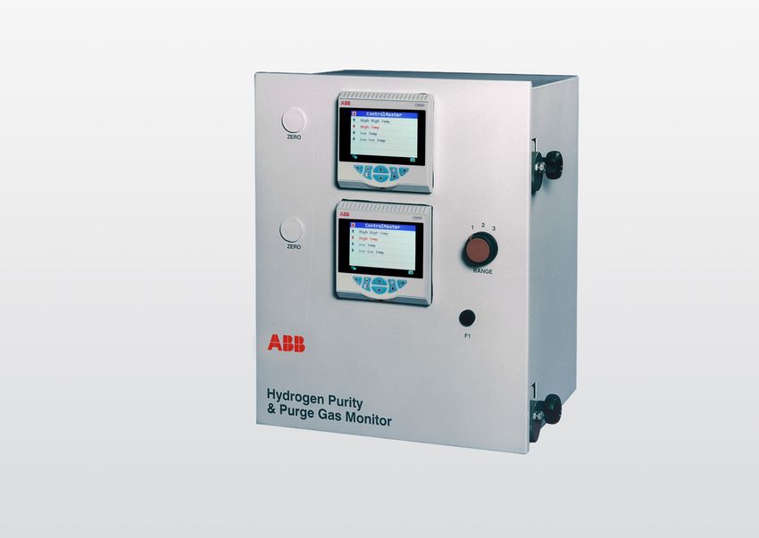
                                                                          • One display monitor containing one digital transmitter
Display monitor                                                             that displays the hydrogen purity range and the purge
The 6553 display monitor includes one or two 4689 digital                   gas ranges. The range selector switch controls the range
transmitters, the range selector switch (excluding GAH200),                 to be displayed.
katharometer remote zero adjustment control and zener
                                                                        GAH200 dual 3-range analyzer
diode safety barriers.
                                                                        100 % redundancy and validation version comprising:
Digital transmitters                                                      • Two gas analysis panels each measuring hydrogen purity
The 4600 series universal transmitter provides the operator                 plus the purge gas ranges.
interface and communication to other devices. The signal                  • Two power supply units.
from the sensing system is converted by the transmitter and               • One display monitor containing two digital transmitters.
the measurement is presented on a large, easy-to read,                      Both the upper and the lower digital transmitters display
backlit liquid crystal display. This display is used in                     the hydrogen purity range and the two purge gas ranges.
conjunction with the four tactile membrane keypads to                       Each digital transmitter has its own range selector switch
prompt the user through the programming procedures. The                     to control the range to be displayed.
transmitter is fitted with two-step alarms for falling hydrogen
                                                                        Operating range
purity.
                                                                        Range for hydrogen purity:
                                                                          • 85 to 100 % H2
                                                                          • 80 to 100 % H2 user selectable

                                                                        Range for purge gas:
                                                                          • 0 to 100 % hydrogen in purge gas*
                                                                          • 0 to 100 % air in purge gas*
                                                                          • Carbon dioxide standard; argon or nitrogen
                                                                            also available.

* Carbon dioxide standard; argon or nitrogen also available
G AH 200 S E RIE S AT EX COMP LI ANT ANALY ZE R SYSTE M | DS/GAH-E N    RE V. A                           5

—
Analyzer panels
The gas sample may be vented to atmosphere or returned to
the generator at an elevated pressure. This panel is equipped
with fittings suitable for such duties and is pressure tested to
10 bar (gauge).

Note. As no certification exists for measurements at
pressures above 1 bar absolute (nominal), it must be
understood that the stated I.S. certification does not cover
use at higher pressures.

                        Hazardous area                                                             Safe area
                         Analyzer panel                                       Power supply units
                             (6548)                                                (4234)                115 or 230 V AC

                                                                                             L                             Monitor
                                                                                                                           (6553)
                                                                                             N
    80 or 85 % to 100 % in air
  0 to 100 % H2 in purge gas*                                                                E
  0 to 100 % air in purge gas*

                                                                                                                       CM30 indicator

                                                                                       115 or 230 V AC

Figure 2 GAH100 single 3-range analyzer system

                        Hazardous area                                                             Safe area
                          Analyzer panel                                      Power supply units
                             (6548)                                                (4234)                115 or 230 V AC

                                                                                              L
                                                                                              N
    80 or 85 % to 100 % in air
  0 to 100 % H2 in purge gas*                                                                 E
                                                                                                                             Monitor
  0 to 100 % air in purge gas*
                                                                                                                             (6553)

                                                                                              L
                                                                                                           CM30 indicator
                                                                                              N

                          Analyzer panel                                                      E
                             (6548)
                                                                                                           CM30 indicator

                                                                                           115 or 230 V AC
      80 or 85 % to 100 % in air
    0 to 100 % H2 in purge gas*
    0 to 100 % air in purge gas*

Figure 3 GAH200 dual 3-range analyzer system

* Carbon dioxide standard; argon or nitrogen also available
6                         GAH 200 SE RIE S AT EX COMP LI ANT ANALY ZE R SYSTE M | DS/GAH-E N    RE V. A

—
Typical installation
The schematic diagram below shows typical arrangements.

                                                                                                  Analyzer panel
        Tapping
          point                                                                                      (6548)

                                             Sample filters

                                              Normally closed *
                                                                                                  Analyzer panel
           Note. All valves except * fully                                                           (6548)
           open during operations                                                              GAH200 systems only

            Sample return
             to generator

Figure 4 System with non-vented sample
G AH 200 S E RIE S AT EX COMP LI ANT ANALY ZE R SYSTE M | DS/GAH-E N    RE V. A            7

—
Specification
6553 gas monitor                                                              Digital I/O
Approvals                                                                     Number
   • CENELEC approved                                                            6
   • [Ex ia Ga] IIC (–20°C ≤ Ta ≤ +40°C)
                                                                              Type
   • BASEEFA Certificate No. BAS 01 ATEX 7043
                                                                                 User-programmable as input or output
   •     II (1)G
                                                                                 Minimum input pulse duration – 125 ms
   • EN61010-1:2010 compliant
                                                                              Input
Ranges
                                                                                 • Volt-free or 24 V DC
   • 80 % or 85 % to 100 % H2 in air
                                                                                 • 1 – signal 15 to 30 V
   • 0 to 100 % H2 in purge gas*
                                                                                 • 0 – signal 3 to 5 V
   • 0 to 100 % air in purge gas*
                                                                                 • Conforms to IEC61131-2
Range selector switch positions (when fitted)
                                                                              Output
1 percentage by volume, hydrogen in air
                                                                                 • Open collector output
2 percentage by volume, hydrogen in purge gas*
                                                                                 • 30 V, 100 mA max. switched
3 percentage by volume, air in purge gas*
                                                                                 • Conforms to IEC61131-2
Accuracy (display units)
                                                                              Update rate
   ± 0.25 % of scale span
                                                                                 125 ms
Ambient temperature range
                                                                              Relays
  0 to 40 °C (32 to 104 °F)
                                                                              No. of relays
Power supply                                                                     4
   110 /120 V AC or 200/220/240 V AC, 50/60 Hz
                                                                              Contact rating
   (two separate versions)
                                                                                 5A, 240 V
Fuse rating
                                                                              Update rate
   F1/F2 500 mA, 250 V AC rated 1500 A @ 250 V AC,
                                                                                 125 ms
   HRC, ceramic, fast blow
                                                                              Set points
Power consumption
                                                                              No. of set points
   30 VA approximately
                                                                                 4
Outline dimensions
                                                                              Set point adjustment
   290 × 362 × 272 mm (11.4 × 14.25 × 10.9 in)
                                                                                 Programmable
Weight
                                                                              Set point hysteresis
   12 kg (26.4 lb)
                                                                                 ±1 % fixed
Environment
                                                                              Local set point annunciation
   Sheltered interior, 0 to 90 % RH
                                                                                 Red LED

                                                                              Analog outputs
                                                                              No. of retransmission signals
                                                                                 2 fully isolated

                                                                              Output current
                                                                                 0 to 10 mA or 0 to 20 mA programmable

                                                                              Accuracy
                                                                                 ±0.25 % FSD ±0.5 % reading

                                                                              Resolution
                                                                                 0.1 % at 10 mA, 0.05 % at 20 mA

                                                                              Max. load resistance
                                                                                750 ohm (20 mA max.)

* Purge gas options include CO2 (carbon dioxide), N2 (nitrogen), Ar (argon)
8                       GAH 200 SE RIE S AT EX COMP LI ANT ANALY ZE R SYSTE M | DS/GAH-E N   RE V. A

—
…Specification
4234 power supply unit                                             6548–000 katharometer analyzer panel
Approvals                                                          Approvals
   • CENELEC approved                                                 • CENELEC approved
   • [Ex ia Ga] IIC (–20°C ≤ Ta ≤ +55°C)                              • Ex ia Ga IIC (–20°C ≤ Ta ≤ +55°C)
   • BASEEFA Certificate No. BAS 01 ATEX 7041                         • BASEEFA Certificate No. BAS 01 ATEX 1042
   •     II (1)G                                                      •     II 1G
   • EN61010-1:2010 compliant                                         • Model 6548–000 incorporating Model 6548–001 (H2 and
Power supply                                                            purge gas) katharometer unit
   115 V AC 50/60 Hz (4234501) or
                                                                   Power supply
   230 V AC 50/60 Hz (4234500)
                                                                      350 mA DC, from 4234500 or 4234501 power supply unit
Power consumption
                                                                   Signal output
   30 W max.
                                                                      0 to 10 mV for each range (air in N2 1.0 mV)
Fuse rating
                                                                   Accuracy
   • T250 mA 250 V AC rated 1500 A HRC ceramic, 250 V AC
                                                                      ± 2 % of scale span, each range
      rated
                                                                      ± 5 % of scale span, air in N2
   • 20 x 5 mm
DC output                                                          Dead time
   350 mA stabilized ±0.14 %                                          Typically 5 s

Load conditions                                                    Response time
   1 Katharometer		                   13 ohm max.                     Typically 40 s for 90 % step change at katharometer
   Interconnecting cable		            2 ohm max.                      (tubing and drying chamber introduce extra delays)

Ambient temperature range                                          Ambient temperature
  –20 to 55 °C (–4 to 131 °F)                                        55 °C (131 °F) max.
                                                                     0 °C (32 °F) min.
Supply variations
   ±15 V (115 V supply) or ±30 V (230 V supply) 46 to 64 Hz        Sample connections
                                                                      Compression couplings:
Regulation
                                                                      • 6 mm OD tube
   Within ± 0.5 % for:
                                                                   Sample pressure
    •   Load variation of ± 15 %                                      Minimum 125 mm H2O
    •   Supply variation of ± 15 %
    •   Ambient temperature variation of ± 20 °C (36 °F)           Sample temperature
    •   ±4 Hz frequency variation                                     0 to 55 °C (32 to 131 °F)

Ripple                                                             Normal sample flowrate
   Less than 0.5 % of set output peak/peak across a 10 ohm            100 to 150ml/min.
   load
                                                                   Maximum gas flowrate
Stability                                                            250 ml/min
   Within ± 0.7 % of initial setting, over period of 1 month
                                                                   Minimum gas flowrate
   with load resistance, supply voltage and ambient
                                                                      50 ml/min
   temperature at nominal stated values
                                                                   Outline dimensions
Overall dimensions
                                                                      610 × 305 × 152 mm (24 × 12 × 6 in.)
   160 × 170 × 110 mm (6.3 × 6.7 × 4.3 in.)
                                                                   Weight
Weight
                                                                      8.6 kg (18.9 lb)
   2.12 kg (4.8 lb) approx.
                                                                   Environment
Environment
                                                                      Sheltered interior
   Sheltered interior
G AH 200 S E RIE S AT EX COMP LI ANT ANALY ZE R SYSTE M | DS/GAH-E N                                    RE V. A                                                    9

 —
 Overall dimensions
 Dimensions in mm (in.)
                                                                            610 (24)                                                                                             148 (6.04)
                                                                                                                                            50 (2.04)
                                                                                                                                                                                                          38 (1.55)
                                                                  572 ±0.3 (23.35 ±0.01)                                                    19 (0.77)
                                                       Gland for Ø7 to 10.5 (0.28 to 0.43) cable    Outlet
                                                                                                                                 Coupling for Ø6 (0.24) tube
                            Ø6 (0.24) tube
                             Coupling for
                   267 ±0.3 (10.9 ±0.01)
305 (12.45)

                                                                                                                                            233 (9.5)
               98 (4) Inlet

                                                                                                                                179 (7.3)
                                               10 (0.41)
              19 (0.77)                                                                                           112 (4.57)     4 fixing holes Ø 10 (0.41)

 Figure 5                     Katharometer analyzer panel assembly (Model 6548–000)

                                         290 (11.84)                  30 (1.22)        272 (11.1)                                                            160 (6.3)                        110 (4.3)

                                                                                                                                                             140 (5.5)                        83 (3.27)

                                                                                                                                                             117 (4.6)
                 362 (14.8)

                                                                 Mounting
                                                                                                    345 (14.08)

                                                                     panel
                                                                 thickness
                                                                     0 – 20
                                                                 (0 – 0.82)                                             Cable entry

                                                                                                                                                                                                              170 (6.7)
                                                                                                                                                 110 (4.3)

                                                                                                                            glands

                                                             Cable
                                                            entries
                                                                            Mounting
                                                                               panel
                                                                              display
                                                                                 face

              Katharometer                     Power and signal
               intrinsically                     conventional
                                                   circuits                                                                                                              4 fixing slots
               safe circuits
                                                                                                                                                                         20 (0.8) long x 10 (0.4) wide

 Figure 6 Model 6553 monitor)                                                                                        Figure 7 Intrinsically safe power supply unit (Model 4234500 or 4234501)

Sales                                        Service             Software
10                           GAH 200 SE RIE S AT EX COMP LI ANT ANALY ZE R SYSTE M | DS/GAH-E N     RE V. A

—
Ordering information
ATEX compliant gas analyzer for hydrogen-cooled alternators
Gas options – system 1

                                                      Gas options – system 1             Gas options – system 2
                                  Power Approvals Range 1   Optional     Optional    Range 1   Optional     Optional Cubicle Flow Language
                                  supply                     range 2      range 3               range 2      range 3        alarms
                           GAH200   X      X     XX XX X XX XX X XX XX X            XX XX X XX XX X XX XX X            X       X     XX
Power supply
115 V                               A
230 V                               B
115 V Intrinsically Safe            C
230 V Intrinsically Safe            D
Approvals
ATEX Class 1 Zone 1                         1
cSGSus                                      2
Gas A
Air                                               A0
Argon                                             A1
Carbon Dioxide                                    C2
Methane                                           C4
Hydrogen                                          H1
Helium                                            H2
Nitrogen                                          N1
Oxygen                                            O2
Special                                           Z9
Gas B
Air                                                    A0
Argon                                                  A1
Carbon Dioxide                                         C2
Methane                                                C4
Hydrogen                                               H1
Helium                                                 H2
Nitrogen                                               N1
Oxygen                                                 O2
Special                                                Z9
AB range
0 – 100 %                                                   1
80 – 100 %                                                  2
85 – 100 %                                                  3
Special                                                     9
Gas C
Not needed                                                      Y0
Air                                                             A0
Argon                                                           A1
Carbon Dioxide                                                  C2
Methane                                                         C4
Hydrogen                                                        H1
Helium                                                          H2
Nitrogen                                                        N1
Oxygen                                                          O2
Special                                                         Z9
Gas D
Not needed                                                           Y0
Air                                                                  A0
Argon                                                                A1
Carbon Dioxide                                                       C2
Methane                                                              C4
Hydrogen                                                             H1
Helium                                                               H2
Nitrogen                                                             N1
Oxygen                                                               O2
Special                                                              Z9
CD range
Not needed                                                                0
0 – 100 %                                                                 1
80 – 100 %                                                                2
85 – 100 %                                                                3
Special                                                                   9
                                                                                                              Gas options – system 1 continued…
G AH 200 S E RIE S AT EX COMP LI ANT ANALY ZE R SYSTE M | DS/GAH-E N    RE V. A                             11

                                            Gas options – system 1              Gas options – system 2
                        Power Approvals Range 1   Optional     Optional     Range 1   Optional     Optional Cubicle Flow Language
                        supply                     range 2      range 3                range 2      range 3        alarms
                 GAH200   X      X     XX XX X XX XX X XX XX X             XX XX X XX XX X XX XX X            X       X     XX
Gas E
Not needed                                                   Y0
Air                                                          A0
Argon                                                        A1
Carbon Dioxide                                               C2
Methane                                                      C4
Hydrogen                                                     H1
Helium                                                       H2
Nitrogen                                                     N1
Oxygen                                                       O2
Special                                                      Z9
Gas F
Not needed                                                        Y0
Air                                                               A0
Argon                                                             A1
Carbon Dioxide                                                    C2
Methane                                                           C4
Hydrogen                                                          H1
Helium                                                            H2
Nitrogen                                                          N1
Oxygen                                                            O2
Special                                                           Z9
EF range
Not needed                                                             0
0 – 100 %                                                              1
80 – 100 %                                                             2
85 – 100 %                                                             3
Special                                                                9
12                 GAH 200 SE RIE S AT EX COMP LI ANT ANALY ZE R SYSTE M | DS/GAH-E N         RE V. A

—
…Ordering information
…ATEX compliant gas analyzer for hydrogen-cooled alternators
Gas options – system 2

                                            Gas options – system 1             Gas options – system 2
                        Power Approvals Range 1   Optional     Optional    Range 1   Optional     Optional Cubicle Flow Language
                        supply                     range 2      range 3               range 2      range 3        alarms
                 GAH200   X      X     XX XX X XX XX X XX XX X            XX XX X XX XX X XX XX X            X       X     XX
Gas A
Air                                                                       A0
Argon                                                                     A1
Carbon Dioxide                                                            C2
Methane                                                                   C4
Hydrogen                                                                  H1
Helium                                                                    H2
Nitrogen                                                                  N1
Oxygen                                                                    O2
Special                                                                   Z9
Gas B
Air                                                                            A0
Argon                                                                          A1
Carbon Dioxide                                                                 C2
Methane                                                                        C4
Hydrogen                                                                       H1
Helium                                                                         H2
Nitrogen                                                                       N1
Oxygen                                                                         O2
Special                                                                        Z9
AB range
0 – 100 %                                                                           1
80 – 100 %                                                                          2
85 – 100 %                                                                          3
Special                                                                             9
Gas C
Not needed                                                                              Y0
Air                                                                                     A0
Argon                                                                                   A1
Carbon Dioxide                                                                          C2
Methane                                                                                 C4
Hydrogen                                                                                H1
Helium                                                                                  H2
Nitrogen                                                                                N1
Oxygen                                                                                  O2
Special                                                                                 Z9
Gas D
Not needed                                                                                   Y0
Air                                                                                          A0
Argon                                                                                        A1
Carbon Dioxide                                                                               C2
Methane                                                                                      C4
Hydrogen                                                                                     H1
Helium                                                                                       H2
Nitrogen                                                                                     N1
Oxygen                                                                                       O2
Special                                                                                      Z9
CD range
Not needed                                                                                        0
0 – 100 %                                                                                         1
80 – 100 %                                                                                        2
85 – 100 %                                                                                        3
Special                                                                                           9
                                                                                                        Gas options – system 2 continued…
G AH 200 S E RIE S AT EX COMP LI ANT ANALY ZE R SYSTE M | DS/GAH-E N   RE V. A                              13

                                             Gas options – system 1             Gas options – system 2
                         Power Approvals Range 1    Optional    Optional    Range 1   Optional     Optional Cubicle Flow Language
                         supply                      range 2     range 3               range 2      range 3        alarms
                  GAH200   X      X     XX XX X XX XX X XX XX X            XX XX X XX XX X XX XX X            X       X     XX
Gas E
Not needed                                                                                      Y0
Air                                                                                             A0
Argon                                                                                           A1
Carbon Dioxide                                                                                  C2
Methane                                                                                         C4
Hydrogen                                                                                        H1
Helium                                                                                          H2
Nitrogen                                                                                        N1
Oxygen                                                                                          O2
Special                                                                                         Z9
Gas F
Not needed                                                                                           Y0
Air                                                                                                  A0
Argon                                                                                                A1
Carbon Dioxide                                                                                       C2
Methane                                                                                              C4
Hydrogen                                                                                             H1
Helium                                                                                               H2
Nitrogen                                                                                             N1
Oxygen                                                                                               O2
Special                                                                                              Z9
EF range
Not needed                                                                                                0
0 – 100 %                                                                                                 1
80 – 100 %                                                                                                2
85 – 100 %                                                                                                3
Special                                                                                                   9

Cubicle/Flow alarms/Language options

Cubicle
Not needed                                                                                                    Y
Included                                                                                                      A
Flow alarms
Not needed                                                                                                          0
Flow alarms kit                                                                                                     1
Flow alarms                                                                                                         2
Language
English                                                                                                                    M5
German                                                                                                                     M1
Italian                                                                                                                    M2
Spanish                                                                                                                    M3
French                                                                                                                     M4
14                          GAH 200 SE RIE S AT EX COMP LI ANT ANALY ZE R SYSTE M | DS/GAH-E N   RE V. A

—
Accessories and spares
Model 6553
Display unit

Description                                                                                                Part number

Fuse, 500 mA 250 V AC rated F 20 × 5 mm ceramic cartridge HBC (1500 A) 250 V AC                              0231 601
Upper function selector switch – AK103 and AK102                                                           006553 511
Lower function selector switch – AK102                                                                     006553 512
Display units carbon dioxide purge                                                                           4689/502
Display units argon purge                                                                                    4689/505
Zener diode safety barrier devices MTL 7055ac                                                                0248 297
Zener diode safety barrier devices MTL 7755ac                                                                0248 296
Low flow alarm (if fitted) | Zener diode safety barrier devices MTL 767+                                     0248 298

Model 4234
Power supply unit (PSU)

Description                                                                                                Part number

Nominal 230 V PSU                                                                                          4234/50000
Nominal 115 V PSU                                                                                          4234/50100

Fuses

Description                                                                                                Part number

F2/F3 – T250 mA/1500 A 250 V AC HBC ceramic cartridge 20 × 5 mm                                              0231577
F1 – 400 mA cartridge                                                                                         0231555

Katharometer analyzer panel

Description                                                                                                Part number

Drying chamber cylinder – acrylic                                                                          006525 720
Drying chamber cylinder – stainless steel                                                                  006548 111
Drying chamber complete – acrylic                                                                          006548 003
Drying chamber complete – stainless steel                                                                  006548 110
Flowmeter (without flow alarms)                                                                              0216 485
Flowmeter (with flow alarms)                                                                                 0216 557
Metering valve                                                                                               0216 484
Katharometer unit                                                                                          006548 001
Drying chamber refurbishment kit                                                                           006548 007
Granular anhydrous CaCl2                                                                                   006537 580
G AH 200 S E RIE S AT EX COMP LI ANT ANALY ZE R SYSTE M | DS/GAH-E N   RE V. A   15
—
ABB Measurement & Analytics

For your local ABB contact, visit:
www.abb.com/contacts

For more product information, visit:
www.abb.com/measurement
                                                                                                   Rev. A 01.2021

We reserve the right to make technical changes or modify the contents of this document without
prior notice. With regard to purchase orders, the agreed particulars shall prevail.
ABB does not accept any responsibility whatsoever for potential errors or possible lack
of information in this document.

We reserve all rights in this document and in the subject matter and illustrations contained
                                                                                                   DS/GAH-EN

therein. Any reproduction, disclosure to third parties or utilization of its contents – in whole
or in parts – is forbidden without prior written consent of ABB.

© 2021 ABB				3KXA834101RXX01
You can also read