EVO Upgrade Kit - Installation Instructions - Capstan Ag
←
→
Page content transcription
If your browser does not render page correctly, please read the page content below
TM

   EVO™
  Upgrade Kit

Compatible with:
   Synchro™
AIM* Command

Installation Instructions

  prodsupport@capstanag.com | 855-628-7722 | www.capstanag.com

 150300-012 Rev. D | Revised 04/2021 | ©2021 Capstan Ag Systems, Inc.
TM

                                      Thank you for your business!
At CapstanAG, our goal is to redefine the way people do their chemical application. Our PWM
control systems have been setting the bar for maximum productivity for more than 20 years.
Our focus on performance, support, and education have dramatically changed the landscape of
agricultural chemical application.

CapstanAG specializes in creating proprietary systems for the agricultural industry, primarily
focusing on chemical and fertilizer applications. Our inventive process involves research,
engineering, design, and lab and field testing.

                                  Service Contact Information
If a problem occurs with your system that cannot be corrected with the information in this
manual, please contact your dealer for service and technical assistance. If further assistance is
needed, contact CapstanAG.

                   System Purchased: _____________________________________
                   Dealer: ______________________________________________
                   Contact: _____________________________________________
                   Phone: _______________________________________________
                   Address: _____________________________________________
                   City,State/Province, Zip: ________________________________

                                      Factory Service/Repairs
                                                CapstanAG
                               4225 S.W. Kirklawn Ave. | Topeka, KS 66609
                                             Hours: 8:00 a.m. to 4:00 p.m. CST

                       Toll-free number: (855) 628-7722 | Fax: (785) 232-7799
                                        CapstanAG.com | CapstanAG.ca
                                           prodsupport@capstanag.com

                  *AIM is a trademark of CNH Industrial LLC, and is not affiliated with Capstan Ag Systems, Inc.

All other trademarks are owned by Capstan Ag Systems, Inc.

©2021 Capstan Ag Systems, Inc. All rights reserved. No part of this publication may be reproduced, stored in a retrieval
system, or transmited, in any form or by means electronic, mechanical, photocopying, or otherwise, without prior written
permission of Capstan Ag Systems, Inc.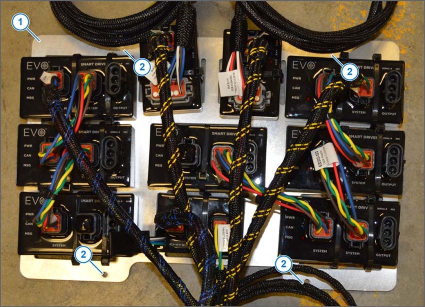
TM

                                                                                                  Before System Installation

    Chapter 1: Before System Installation
                                                                                       1
           The EVO™ Upgrade kit is compatible with existing Synchro™ and AIM Command systems.
           Before assembly and installation, read the installation information carefully. Make sure that you
           have all of the parts in the kits. Read all of the instructions in this document, the system operator
           manual, and the machine manuals. The system operator manual includes information on operation,
           adjustments, troubleshooting, and maintenance.
                      Attention: The correct function of the EVO™ system cannot be guaranteed if the current
                      PWM system is not functioning correctly. Do the following procedures BEFORE installation to
                      verify the correct function of the existing system.
                      No warranty or returns of the system will be honored if the existing system is not verified to
                      function correctly before installation of the EVO™ system.
           For further assistance, contact your CapstanAG representative.
           Before installation of a new system, you must make sure that the existing AIM Command system is
           operating correctly. Do these procedures:
                •     Clean the nozzle valves and inspect the plunger seals
                •     Do a Check of the Conventional Spray System
                •     Do a Check of the System Flow Control
                •     Do a Check of the System Pressure Control

    Clean the Nozzle Valve(s)
                      Warning: Chemical residues may be present in the agricultural equipment. Always use
                      proper personal equipment to avoid personal injury.

           1.       Release pressure from the system before servicing.
           2.       Clean the system before installation or service of the fittings, hoses, valves, or nozzles.
           3.  Remove the valve body.
           4.  Remove the plunger.
           5.  Inspect the O-rings.
           6.  Wash the nozzle valve components to remove any debris.
           7.  Inspect the plunger for wear or damage.
           8.  If there is wear or damage to the plunger, replace the plunger.
           9.  Inspect the valve body.
               Make sure that the orifice is not plugged with debris, worn, or damaged.
           10. If there is wear or damage to the orifice, replace the valve body.
           11. Wash the nozzle body components to remove any debris.
                    Important: Do not use brake cleaner. Brake cleaner can damage the seal.
                    Important: During installation, apply 40 lbf in of torque to the coil when it threads into the valve
                    body to properly seat the O-ring.

       1
            AIM is a trademark of CNH Industrial LLC, and is not affiliated with Capstan Ag Systems, Inc.

© 2021 Capstan Ag Systems, Inc.                                         3                                         EVO Upgrade Kit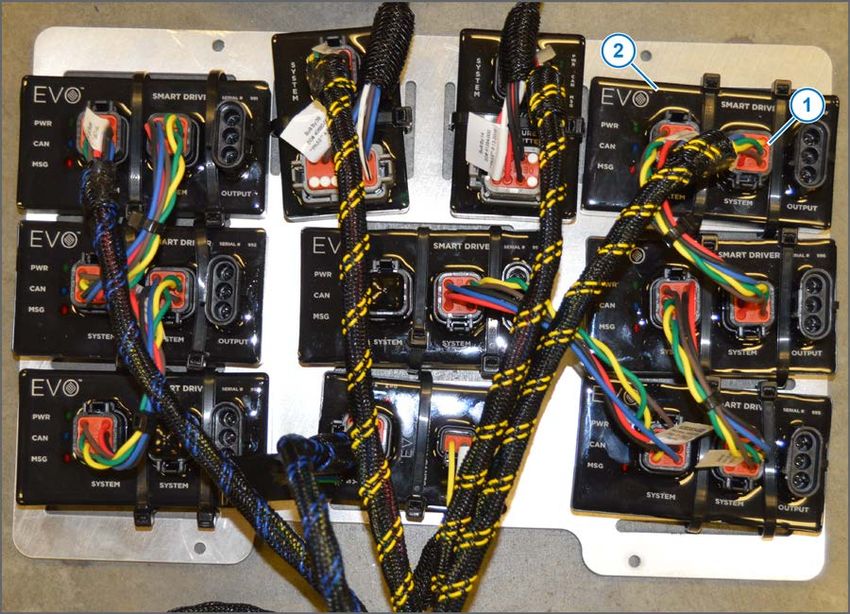
TM

                                                                                            Before System Installation

       Plunger Seal Inspection

         Figure 1:

         After extended use, the plunger seal will wear a groove (1) where the seal impacts the hard orifice
         seat. Replace the plunger if worn or damaged.
         As the groove deepens, the pressure capacity of the valve will decrease until the pressure capacity
         interferes with the operating pressure of the system.
         The result is erratic pulsing, often described as “flickering.” The system will operate normally at lower
         pressures until replacement parts can be installed. High operating pressures and abrasive chemicals
         will accelerate the wear of the plunger seal material.

© 2021 Capstan Ag Systems, Inc.                                   4                                     EVO Upgrade Kit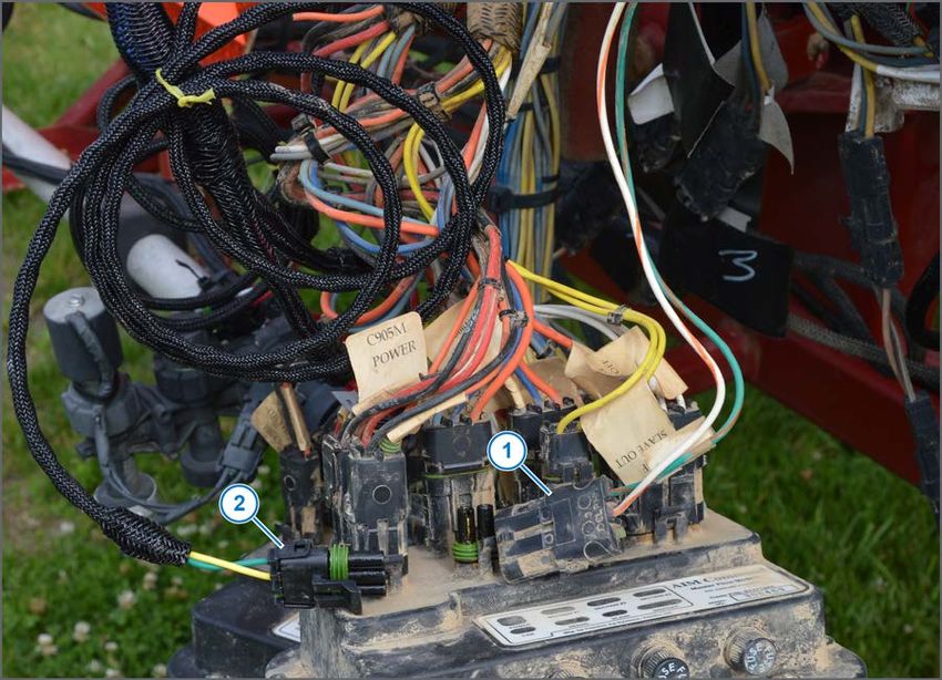
TM

                                                                                            Before System Installation

    Do a Check of the Conventional Spray System
         Before installation of the EVO™ Upgrade Kit, make sure that the existing system operates in the
         conventional spray mode correctly.

         1.   Open the intermediate bodies (through bodies) on the spray booms and move existing tips to
              those bodies if no other tips are installed.
         2.   Move the Auto/Off/Manual switch to the O position.
         3.   Turn on the key switch for the machine.
         4.   Power on the rate controller.
         5.   On the rate controller, change the control valve type to PWM or PWM/AIM Command PRO.
         6.   On the rate controller, set a test speed.
         7.   On the rate controller, enter a target rate.
         8.   Turn on the master switch and the boom switches.
              If the system sprays and maintains the target rate, continue to the installation.
              If the system does not operate correctly, find and correct the problem(s) before continuing with
              the EVO™ upgrade installation.

    Do a Check of the Existing System Flow Control
         1.   Make sure that the intermediate valve bodies are closed and nozzles are placed on the bodies
              with blended pulse solenoids in place.
         2.   Turn on the key switch for the machine.
         3.   Power on the rate controller.
         4.   Change the control valve type to:
               •    AIM Command
               •    Inline servo
         5. Set a test speed in rate controller.
         6. Disable any automatic section control feature in the rate controller.
         7. Set the rate controller to manual rate mode.
         8. Move the Auto/Off/Manual switch to A position.
         9. Turn on the boom section switches and master switch.
         10. Press the manual rate increase button on the rate controller to a maximum flow.
             You should see no pulsing of the system.
         11. Press the manual rate decrease button on the rate controller to a minim flow.
             You should see a very distinct pulsing of the system.

         If these steps are completed successfully continue to the next procedure: Do a Check of the Existing
         System Pressure Control.

© 2021 Capstan Ag Systems, Inc.                                   5                                     EVO Upgrade Kit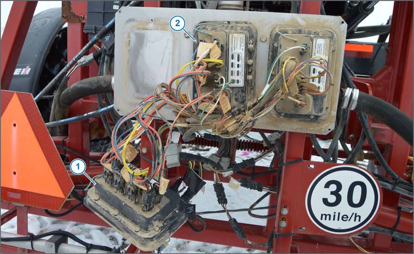
TM

                                                                                    Before System Installation

    Do a Check of the Existing System Pressure Control
         1.  Turn on the key switch for the machine.
         2.  Move the Auto/Off/Manual switch to the O position and start the machine.
         3.  Idle the machine and move the Auto/Off/Manual switch to the A position.
         4.  Move the throttle to half-open.
             The pressure should move to the pressure setpoint and hold that pressure.
         5. Move the pressure control switch to the + position.
             The pressure should increase.
         6. Move the pressure control switch to the – position.
             The pressure should drop.
         7. Use the pressure control switch to set the pressure near 50 psi.
         8. If the pressure will not reach 50 psi, bump the throttle up.
         9. Move the P1/P2 switch to the other position.
             The pressure should move to the second set point pressure.
         10. Use the pressure control switch to set the second pressure at 20 psi.
         11. Toggle between the P1 and P2 positions.
             The system pressure should move back and forth between 20 and 50 psi. The transition should
             take a second or so, and the pressure may go past but should come right back to the target
             pressure.
         12. If the pressure seems unstable, a PWM cartridge test should be performed.
             Contact CapstanAG for the tuning procedure.

© 2021 Capstan Ag Systems, Inc.                              6                                  EVO Upgrade Kit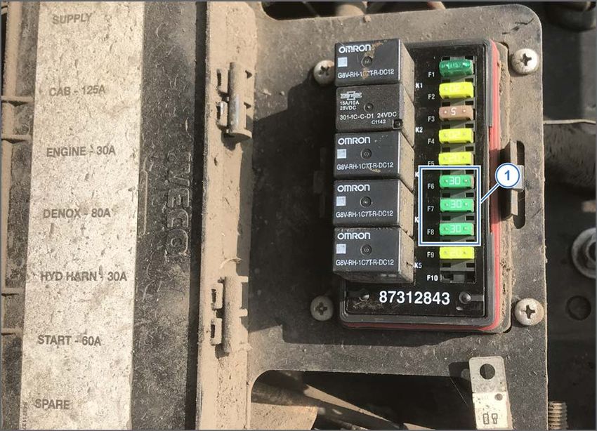
TM

                                                                                                       Kit Parts List

    Chapter 2: Kit Parts List
             Part                         Description                   Parts Description                 Qty
            Number
          116200-014         3-pin Extension Harness-4 ft    Extension 3-Conductor x 4ft, 14 ga            4
          116200-045         2-Pin Tower Dust Plug           HN Dust Plug 2 Pin Tower WP                   4
          116200-046         3-Pin Tower Dust Plug           HN Dust Plug 3 Pin Tower WP                   2
          116200-048         3-Pin Shroud Dust Plug          HN Dust Cap 3 Pin Shroud WP                   7
          116200-051         2-Pin Shroud Dust Plug          Dust Plug, 2 Pin WP Shroud                    2
          116200-078         4-Pin Tower Dust Plug           HN Dust Plug 4 Pin Tower WP                   4
          120140-016         DB9 Serial Cable                Cable Serial DB9 MTOF 15'                     1
          120140-028         8-32 Male/Female Hex Standoff   Hex Standoff, M/F 8-32 SS                     4
          150003-005         CAN Terminator                  CAN Terminator                                2
          150006-010         Cab Box Display                 Cab Box Display Assy EVO                      1
          150150-010         Pressure Transmitter Module     Assembly, Pressure Transmitter, EVO           1
          150200-010         Boom Transmitter Module         Assembly, Boom Transmitter A, EVO             1
          709031-505         8-32 x 5/16 Screw               Screw #8-32 X 5/16" SSPAN SS                  4
          713501-508         Split Lock Washer               Washer #8 Split Lock, SS                      4
          715040-178         Cable Ties                      Tie Cable 12" Black                           68
          150005-008         PSI Adapter Harness             Harness, Adapter PSI EVO-AC Upgrade           1
          150300-001         Mounting Plate                  Module Mount Plate, EVO AC Retro              1
          150100-010         Smart Driver Module             Assembly, Controller, Smart Driver, EVO       7
          150003-006         Power to CAN X Harness          Power to Can X for AC Retro                   1
          118606-601         Shutoff Harness                 Harness, Shutoff, Aim-Evo at Aim Module       1
          150004-040         CAN-Bus Extension Harness-40 ft Harness, Ext, CAN-BUS, 40FT Plug to           1
                                                             Plug
          150003-004         Display Harness with GPS Drop   Harness, Display w/GPS Drop                   1
          116200-077         4-Pin Tower Square Dust Plug    HN Dust Plug 4 Pin Tower SQWP                 1
          118603-111         RAM Mount                       RAM Mount 2 7/16" Rnd Base 1"UBolt            1
                                                             base w/1.5" Ball
          620303-023         Plug-to-Plug Adapter Harness    Harn, Adapter, Plg-Plg 6"                     5
          150005-010         Servo Adapter Harness           Harness, Adapter, Servo, for AC               1
          150250-050         Servo Transmitter Module        Assembly, Controller Servo, EVO               1
          705725-141         20 A Fuse                       Fuse 20 Amp Type ATO/ATC YL                   3

© 2021 Capstan Ag Systems, Inc.                                 7                                  EVO Upgrade Kit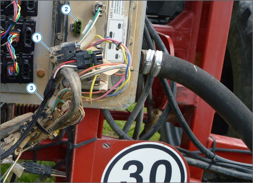
TM

                                                                                               Kit Parts List

             Part                      Description              Parts Description                 Qty
            Number
          705725-150         20 A Mini Fuse          Fuse, 20 Amp, Mini ATC                        3
          706530-356         12-pin D Dust Plug      HN Dust Plug 12-Pin Deutsch DT A Key          1
            Machine          GPS Adapter Cable       See Technical Bulletin TB19-04 for more       1
            Specific                                 information about which cable is needed
                                                     for your system.

© 2021 Capstan Ag Systems, Inc.                         8                                   EVO Upgrade Kit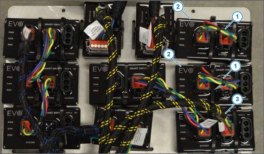
TM

                                                                                                Kit Parts List

    System Layout

       Seven-section Schematic

         Figure 2:

           Callout                Description              Callout              Description
              (1)      Mounting Plate                        (6)     PSI Adapter Harness
              (2)      Plug-to-Plug Adapter Harness-6 in     (7)     Shutoff Harness
              (3)      CAN Terminator                        (8)     Cab Box Display
              (4)      Power to CAN X Harness                (9)     Display Harness with GPS Drop
              (5)      Servo Adapter Harness                (10)     CAN-Bus Extension Harness-40 ft

© 2021 Capstan Ag Systems, Inc.                             9                                 EVO Upgrade Kit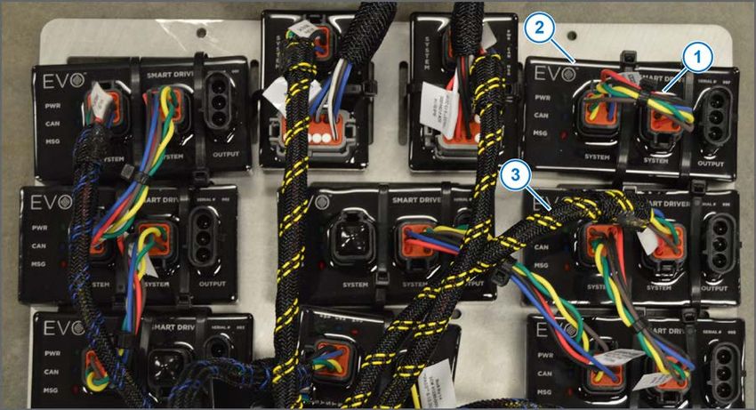
TM

                                                                                                Kit Parts List

       Six-section Schematic

         Figure 3:

           Callout                Description              Callout              Description
              (1)      Mounting Plate                        (6)     PSI Adapter Harness
              (2)      Plug-to-Plug Adapter Harness-6 in     (7)     Shutoff Harness
              (3)      CAN Terminator                        (8)     Cab Box Display
              (4)      Power to CAN X Harness                (9)     Display Harness with GPS Drop
              (5)      Servo Adapter Harness                (10)     CAN-Bus Extension Harness-40 ft

© 2021 Capstan Ag Systems, Inc.                            10                                 EVO Upgrade Kit
TM
Kit Parts List
Five-section Schematic
Figure 4:
Callout Description Callout Description
(1) Mounting Plate (6) PSI Adapter Harness
(2) Plug-to-Plug Adapter Harness-6 in (7) Shutoff Harness
(3) CAN Terminator (8) Cab Box Display
(4) Power to CAN X Harness (9) Display Harness with GPS Drop
(5) Servo Adapter Harness (10) CAN-Bus Extension Harness-40 ft
© 2021 Capstan Ag Systems, Inc. 11 EVO Upgrade KitTM
Kit Parts List
© 2021 Capstan Ag Systems, Inc. 12 EVO Upgrade KitTM
Installation—EVO™ Upgrade Kit
Chapter 3: Installation—EVO™ Upgrade Kit
Figure 5:
1. Mount the cab display (1) in the cab of the machine with the hardware (2) supplied with the kit.
Make sure that the cab display is within view and reach of the operator.
Figure 6:
2. Install one end of the display harness (1) into the connector at the back of the cab display (2).
3. Route the display harness to the back of the cab of the machine.
4. Connect the GPS connector (3) to the machine-specific GPS Y-cable.
5. Connect the other end of the GPS Y-cable to the existing GPS source.
6. At the back of the cab, connect the display harness to the CAN Bus extension harness—40ft (4).
7. Route the CAN Bus extension harness—40ft to the back of the machine.
© 2021 Capstan Ag Systems, Inc. 13 EVO Upgrade KitTM
Installation—EVO™ Upgrade Kit
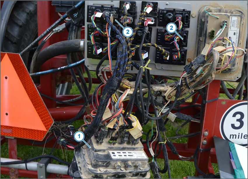
Figure 7:
8. Remove the module cover from the back from the sprayer.
9. Remove the master (1) and slave flow control modules (2) from the existing mounting plate(s).
Do not disconnect the harness connectors at this time.
© 2021 Capstan Ag Systems, Inc. 14 EVO Upgrade KitTM
Installation—EVO™ Upgrade Kit
Figure 8:
10. Install the standoffs (1) to the existing mounting plate.
© 2021 Capstan Ag Systems, Inc. 15 EVO Upgrade KitTM
Installation—EVO™ Upgrade Kit
Figure 9:
11. Install the module mounting plate (1) to the standoffs with the screws (2) and lock washers.
Make sure that all of the screws can be installed before tightening the screws all the way.
Figure 10:
12. Connect the Display, Left Trunk connector (1) of the power to CAN X harness to the end of the
CAN Bus extension harness—40ft (2).
13. Route the shutoff adapter harness (3) connected to the boom signal transmitter module to the
back of the mounting plate.
© 2021 Capstan Ag Systems, Inc. 16 EVO Upgrade KitTM
Installation—EVO™ Upgrade Kit
Figure 11:
14. Disconnect the existing boom shutoff connectors (1).
The existing boom shutoff connectors may be located behind the mounting plate and to the left of
the center rack of the machine.
To verify the correct connectors follow the harness from the AIM Command modules along the
existing AIM Command harnessing.
15. Connect the shutoff adapter harness connector (2) to the existing boom shutoff connector.
16. Install a dust plug to the other existing connector.
© 2021 Capstan Ag Systems, Inc. 17 EVO Upgrade KitTM
Installation—EVO™ Upgrade Kit
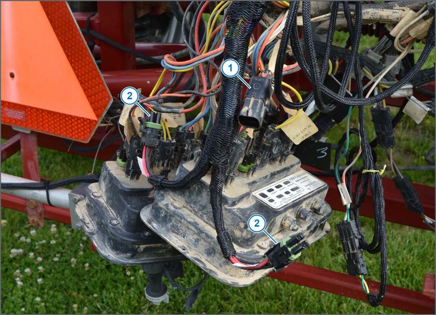
Figure 12:
17. Disconnect the connector (1) labeled SERVO from the master flow module.
18. Connect the servo adapter harness (2) connected to the servo transmitter module to the master
servo connector.
© 2021 Capstan Ag Systems, Inc. 18 EVO Upgrade KitTM
Installation—EVO™ Upgrade Kit
Figure 13:
19. Disconnect the connector (1) labeled SENSOR from the pressure module (2).
20. Connect the pressure adapter harness (3) from the pressure transmitter module between the PSI
connector and the pressure module as shown.
© 2021 Capstan Ag Systems, Inc. 19 EVO Upgrade KitTM
Installation—EVO™ Upgrade Kit
Figure 14:
The smart drivers have been assembled in serial number order from smallest to largest. The lowest
serial number smart driver will drive the leftmost section of the system.
(1) Smart Driver #1—Section 1
(2) Smart Driver #2—Section 2
(3) Smart Driver #3—Section 3
(4) Smart Driver #4—Section 4
(5) Smart Driver #5—Section 5
(6) Smart Driver #6—Section 6
(7) Smart Driver #7—Section 7
© 2021 Capstan Ag Systems, Inc. 20 EVO Upgrade KitTM
Installation—EVO™ Upgrade Kit
Figure 15:
21. If the system has 6 sections or less, disconnect right boom/right trunk connector on the power to
CAN X harness (1) from smart driver #7 (2).
© 2021 Capstan Ag Systems, Inc. 21 EVO Upgrade KitTM
Installation—EVO™ Upgrade Kit
Figure 16:
22. For six sections, remove one end of the plug-to-plug harness (1) between the smart driver #7 (2)
and smart driver #6 and use the connectors as dust plugs on smart driver #7 as shown.
23. Connect the right boom/right trunk connector (3) on the power to CAN X harness to smart driver
#6 as shown.
© 2021 Capstan Ag Systems, Inc. 22 EVO Upgrade KitTM
Installation—EVO™ Upgrade Kit
Figure 17:
24. For five sections, remove one end of the plug-to-plug harnesses (1) between the smart driver #7
and #6 (2) and use the connectors as dust plugs on the unused smart drivers as shown.
25. Connect the right boom/right trunk connector (3) on the power to CAN X harness to smart driver
#5 as shown.
© 2021 Capstan Ag Systems, Inc. 23 EVO Upgrade KitTM
Installation—EVO™ Upgrade Kit
Figure 18:
26. For all systems, disconnect the section connectors from the master and slave modules (1).
27. Connect the section connectors to the correct port (2) on each smart driver.
If necessary, use a 4-ft 3-pin extension harness between the smart drivers and the existing
harnessing.
Section 1 will be connected to the smart driver with the lowest serial number that is being used.
Five and six section systems will not use all of the smart drivers.
© 2021 Capstan Ag Systems, Inc. 24 EVO Upgrade KitTM
Installation—EVO™ Upgrade Kit
Figure 19:
28. Disconnect the existing power connectors (1) from the master and slave flow modules.
29. Connect the existing power connectors to the left and right trunk power connectors (2) of the
power to CAN X harness.
30. Do not disconnect or remove the existing control bypass module.
This module is required to bypass control back to the rate controller if conventional spray control
is desired.
© 2021 Capstan Ag Systems, Inc. 25 EVO Upgrade KitTM
Installation—EVO™ Upgrade Kit
Figure 20:
31. Replace any existing fuses is the F6, F7, and F8 locations (1) with the correct type of 20 A fuses
supplied in this kit.
The fuse panel shown is for reference only. The fuse panel shown may be different than your
machine.
32. Install dust plugs as needed.
33. Install the module cover.
© 2021 Capstan Ag Systems, Inc. 26 EVO Upgrade KitTM
System Setup
Chapter 4: System Setup
Before setting up the EVO upgrade system, make sure that you know how the sections are
configured on the machine.
Common system configurations with 20-in spacing include:
Boom Width in ft Number of Nozzles Total Section Number
Sections Per Section Nozzles
1 2 3 4 5 6 7
80 6 6-9-9-9-9-6 48 6 9 9 9 9 6
90 5 9-15-6-15-9 54 9 15 6 15 9
90 6 9-9-9-9-9-9 54 9 9 9 9 9 9
100 6 12-9-9-9-9-12 60 12 9 9 9 9 12
120 7 9-9-14-8-14-9-9 72 9 9 14 8 14 9 9
Figure 21:
1. Press the POWER button (1) on the cab box display to turn on the display.
2. Press the MENU button (2) to go to the Main Menu screen (3).
3. Use the arrow buttons (4) to go to the Advanced Menu line (5).
4. Press the ENTER button (6).
5. Use the arrow buttons to go to the Module Location Menu line (7).
6. Press the ENTER button.
7. Use the arrow buttons to scroll to the Reset Serial Numbers line (8) on the Module Location
screen.
8. Make sure that the order of the smart drivers on the Module Location screen matches the
physical boom layout. Change the order if necessary.
The smart drivers should be in serial number order from left to right (lowest to highest number).
© 2021 Capstan Ag Systems, Inc. 27 EVO Upgrade KitTM
System Setup
9. Use the arrow buttons to scroll to Section #1 line.
10. Press the ENTER button.
The nozzles on the selected section must pulse. If the nozzles do not pulse, the smart driver is in
the wrong location.
a) To change the location, press the ENTER button until the line is highlighted yellow.
b) Use the arrow buttons to move the smart driver to the correct location.
c) Press the ENTER button.
11. Use the arrow buttons to scroll to the next Section line.
12. Repeat Steps 11 and 12 to test the rest of the system sections.
13. Use the arrow buttons to go to the Section Size line (9) on the Advanced Menu screen.
14. Press the ENTER button.
15. On the Section Size screen, Section #1 Nozzles is selected (10), press the ENTER button.
16. Enter the correct number of nozzles for that section.
17. Press the ENTER button.
18. Use the arrow buttons to go to the line for the next section (11).
19. Press the ENTER button.
20. Enter the correct number of nozzles for that section.
21. Press the ENTER button.
22. Repeat steps 10 to 13 for each additional section of your machine.
23. When the correct number of nozzles for each section has been entered, press the ESCAPE
button (12) to go to the Advanced Menu screen.
24. Press the ESCAPE button three times to go to the main operating screen on the display.
25. Power cycle the display.
26. Make sure that you have a GPS connection.
A GPS error will show at the bottom of the main operating screen if the system is not receiving
the correct GPS signal.
Go to the Diagnostics line (13) that shows the GPS baud rate.
If the baud rate is showing on the Diagnostics screen (14), you have good a good GPS
connection. Then verify that the correct NMEA information is being sent from the exported
information from you GPS. The EVO™ system requires VTG and GGA with a minimum of 5 Hz
and 10 Hz recommended.
The EVO™ system requires a baud rate between 19200 to 115200.
If no baud rate is present, do a check of all the GPS connection points.
© 2021 Capstan Ag Systems, Inc. 28 EVO Upgrade KitYou can also read