ILD8150 in tunable white and multichannel LED applications
←
→
Page content transcription
If your browser does not render page correctly, please read the page content below
AN_2004_PL39_2006_121319

   ILD8150 in tunable white and multichannel LED
   applications

   About this document

   Scope and purpose
   Tunable white and multichannel LED lighting are increasingly popular applications and they are becoming
   more standardized. They enable adjustment of the comparative color temperature (CCT) in the range of 2700 to
   6500 K. Color temperature positively affects human activity during the day. In the morning, a cold color
   temperature is desirable, as this keeps us awake and alert. In the evening, a warm color temperature will help
   us relax and rest. Some systems are designed to make adjustments automatically according to the time of day.
   Besides being used in hospitals, schools and offices, tunable white lighting is also widely used in retail outlets,
   where proper color temperature can make products look more attractive and increase sales. Multiple light
   sources must be aligned to have the same comparative color temperature with high accuracy to prevent visible
   color difference.
   Furthermore, multichannel LED lighting is also popular in horticultural LED lighting. A combination of four
   colors – deep blue, hyper-red, far-red and white – are used to achieve more effective energy use. Multichannel
   RGB lighting is also quite popular in architectural lighting and entertainment applications.
   This document describes a multichannel application as a system and includes tips on how to properly design it.

   Intended audience
   This document is intended for engineers and students designing highly efficient LED drivers with adjustable
   light temperature or adjustable light color.

   Table of contents
   Table of contents ............................................................................................................................ 1
   1      System description................................................................................................................. 2
   2      Schematics and performance .................................................................................................. 3
   3      Design hints ........................................................................................................................... 9
   4      References for related documents and tunable white/dimming engines ...................................... 11
   Revision history............................................................................................................................. 12

   Aplication Note           Please read the Important Notice and Warnings at the end of this document                                        V 1.0
   www.infineon.com/ref-tw-ild8150e-60v-1a                  page 1 of 13                                                                2021-01-29
ILD8150 in tunable white and multichannel LED applications
System description

1                   System description
A typical tunable white LED driver block diagram is shown in Figure 1. Usually, such systems consist of two or
more identical channels of a buck or linear stage connected to the AC-DC source with constant output voltage.
Every channel supplies the dedicated LED string with a certain color temperature or color. The ratio between
currents in the channels gives the desired result. A control circuit provides analog or pulse-width modulated
(PWM) signals to the buck/linear stages. It is usually supplied from the same AC-DC PFC stage through an
auxiliary winding supply or from a DC-DC converter deriving the voltage from the main channel.

                          Tunable-white LED driver

                                                               DC/DC buck
    AC Input                  PFC isolated
                                                                (Linear)

                                      Aux.
                                     Supply

                                                               DC/DC buck
                                                                (Linear)
            Color
                                    Tunable-
                                     white/
                                    dimming
           Dimming

Figure 1            Tunable white block diagram

The tunable white/dimming circuit engine can be wired or wireless. It can be programmed to change the
dimming level according to the lighting sensor information, and the light color can be synchronized to the real-
time clock to produce more natural light. The system can also be integrated into IoT infrastructure with many
sensors, to turn lights on and off and control brightness level and color.
The engine supply and other important subjects are described in section 2. Tunable white and multichannel
lighting may appear quite simple, but there are many details that can affect system performance.

Aplication Note                                      2 of 13                                                 V 1.0
                                                                                                       2021-01-29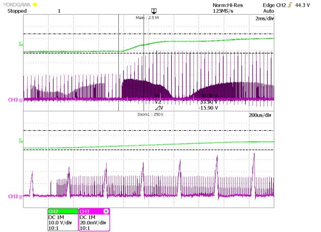
ILD8150 in tunable white and multichannel LED applications
Schematics and performance
2 Schematics and performance
Board features:
Input voltage range: 16 to 70 V DC
Input auxiliary voltage range: 5 to 15 V DC
Output LED voltage: 10 to 56 V DC
Output LED current: 600 to 1050 mA
Dimming range: 0.5 to 100 percent
Channels ratio: 0 to 100 percent
Output auxiliary voltage: 3.3 V DC
Output auxiliary current: Less than 60 mA
Standby current consumption of the two channels: Less than 280 µA
Board dimensions: 120 mm (L) × 27 mm (B) × 20 mm (H)
Table 1 Values
Jumper X9(X29)A Jumper X9(29)B Jumper X9(29)C Output current (mA)
– V – 600 (+/-3 percent)
V V – 700 (+/-3 percent)
– – V 1050 (+/-3 percent)
The tunable white solution based on ILD8150E, shown in Figure 2, consists of two identical channels and one
auxiliary 3.3 V supply. To achieve higher light quality it employs output electrolytic capacitors of 47 μF to
smooth output current. An electrolytic capacitor of 1000 μF/16 V and an LDO, IFX1117ME V33, are used to
provide a smooth supply of 3.3 V and up to 60 mA for the dimming control circuit (e.g. a microcontroller). Two
channels operate at frequencies of up to 500 kHz, which minimizes the bus fluctuation effect on current
accuracy described earlier. Jumpers X9 and X29 change output current in the range 250 to 1500 mA. The board
also includes connector X41, which provides 3.3 V, dimming inputs of the channels, and one common shutdown
pin, which puts the buck converters into standby mode.
DC input
J2 - +
LED1
+ -
GND VIN
LED2
+ -
Vaux
LED1 3.3V SD DIM1 LED2
current setting DIM2 current setting
Figure 2 ILD8150E tunable white evaluation board
Aplication Note 3 of 13 V 1.0
2021-01-29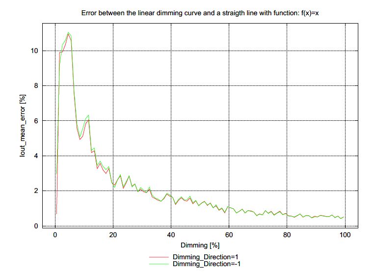
ILD8150 in tunable white and multichannel LED applications
Schematics and performance

Figure 3 shows the modular system with a primary stage based on XDPL8219, a feedback board and the
tunable white board. XDPL8219 is a digital high-performance secondary-side regulated flyback controller with
a high power factor and constant voltage output. By using plug and play Infineon’s REF-XDPL8219-U40W (40 W
high power factor flyback converter) can simply be combined with the secondary side. This enables a very
efficient solution for a tunable white LED driver.

The modular method enables changing the configuration quite easily, so the secondary-stage buck could be
exchanged to a linear stage. REF_TW_BCR601_55V_0.5A is such a reference solution, with the linear LED drivers
BCR601 and BCR602. This combination with a secondary-side linear regulator enables an efficient as well as
cost effective solution for a tunable white LED driver with highest light quality.

Figure 3          Modular concept – primary stage, constant voltage feedback, ILD8150E tunable white

Figure 4 and Figure 5 show the board schematics and the layout, respectively.

Figure 4          ILD8150E tunable white evaluation board circuit

Aplication Note                                     4 of 13                                               V 1.0
                                                                                                    2021-01-29
ILD8150 in tunable white and multichannel LED applications
Schematics and performance
Figure 5 ILD8150E tunable white PCB top and bottom
Attention: Making LED connections across different channels will damage the board!
System efficiency at 230 V AC/50 Hz over the dimming range at equal input power up to 30 W with different LED
numbers is shown in Figure 6. Jumpers X9 and X29 are used for maximum LED current setting to achieve equal
input power.
Efficiency vs dimming
100
95
90
Efficiency (%)
85
80
75
70
10 20 30 40 50 60 70 80 90 100
Dimming (%)
17 LEDs 13 LEDs 10 LEDs
Figure 6 System efficiency over dimming at 50/50 percent channels split with different numbers of
LEDs at equal output power. 17 X9 LEDs, X29 jumpers at positions 3 to 4, 13 X9 LEDs, and
X29 jumpers at positions 1 to 2 and 3 to 4, 10 X9 LEDs, and X29 jumpers at positions 5 to 6.
Aplication Note 5 of 13 V 1.0
2021-01-29ILD8150 in tunable white and multichannel LED applications
Schematics and performance
Power efficiency, THD and power factor are shown in Figures 7 to 9.
Power efficiency
90
88
86
84
Efficiency (%)
82
80
78
76
74
72
70
10 20 30 40 50 60 70 80 90 100
Dimming (%)
90V 110V 230V 277V
Figure 7 System efficiency over dimming for different input voltages. Maximum output power
43 W.
THD
10
9
8
7
THD (%)
6
5
4
3
2
1
0
10 20 30 40 50 60 70 80 90 100
Dimming (%)
90V 110V 230V 277V
Figure 8 THD over dimming for different input voltages. Maximum output power 43 W.
Aplication Note 6 of 13 V 1.0
2021-01-29ILD8150 in tunable white and multichannel LED applications
Schematics and performance
Power factor
1,00
0,95
0,90
Power factor
0,85
0,80
0,75
0,70
10 20 30 40 50 60 70 80 90 100
Dimming (%)
90V 110V 230V 277V
Figure 9 Power factor over dimming for different input voltages. Maximum output power 43 W.
Because the board has one common SD pin, the dimming engine provides an SD signal, which puts it into
standby mode. The IC consumption in standby mode is about 100 μA, so two channels consume about 16 mW.
The bill of materials (BOM) is listed in Table 2, below.
Aplication Note 7 of 13 V 1.0
2021-01-29ILD8150 in tunable white and multichannel LED applications
Schematics and performance
Table 2 Bill of materials
# Quantity Designator Description Manufacturer Manufacturer part
number
1 2 C1, C21 Capacitor 4.7 µF/100 V/1210/10 percent TDK C3225X7S2A475K200AB
2 2 C2, C22 Capacitor 100 nF/100 V/1206/X7R/10 TDK C3216X7R2A104K160AA
percent
3 2 C4, C24 Capacitor 10 nF/100 V/1206/X7R/10 Murata GRM319R72A103KA01
percent
4 2 C5, C25 Capacitor 47 µF/100 V/radial/20 percent Panasonic EEU-FS2A470L
5 2 C6, C26 Capacitor 22 nF/100 V/0805/X7R/10 Murata GRM216R72A223KAC4
percent
6 3 C7, C27, C48 Capacitor 100 nF/50 V/603/X7R/10 percent AVX 06035C104K4Z2A
7 2 C8, C28 Capacitor 100 pF/50 V/ KEMET C0603C0G1H101J030BA
CAPC1608X90N/C0G/5 percent
8 2 C9, C29 Capacitor 180 pF/50 V/0603/C0G/ Murata GRM1885C1H181JA01
5 percent
9 2 C11, C31 Capacitor 10 pF/50 V/0603/C0G/5 percent Murata GCM1885C1H100JA16
10 1 C49 Capacitor 1 mF/16V/THT/20 percent TDK Corporation B41888C4108M000
11 7 CS, CS2, 5000/CON-THT-TP-5000 Keystone 5000
GND, SW,
SW2, VIN, X5
12 2 D1, D21 Diode 2 A/100 V/SOD-123F ON MBR2H100SFT3G
Semiconductor
13 2 D2, D22 Diode SMBJ43A/DO-214AA ON SMBJ43A
Semiconductor
14 1 G41 Power IFX1117ME V33/PG-SOT223 Infineon IFX1117ME V33
Technologies
15 1 J1 691309510004 Würth Elektronik 691309510004
16 3 J2, J4, J22 691412320002 Würth Elektronik 691412320002
17 1 J3-J Jumper black Samtec SNT-100-BK-T
18 2 L2, L22 Inductor 100 µH/1210 Würth Elektronik 7447709101
19 2 R1, R21 Resistor 1.5 k/150 V/0805/1 percent Vishay CRCW08051K50FK
20 2 R2, R20 Resistor 18.2 R/200 V/1206/1 percent Vishay CRCW120618R2FK
21 6 R3, R4, R6, Resistor 4.30 R/1206/1 percent Vishay CRCW12064R30FK
R23, R24,
R26
22 2 R7, R27 Resistor 3.60 R/1206/1 percent Vishay CRCW12063R60FK
23 4 R8, R9, R28, Resistor 2.05 R/1206/1 percent Vishay CRCW12062R05FK
R29
24 4 R10, R11, Resistor 1.33 R/1206/1 percent Vishay CRCW12061R33FK
R30, R31
25 2 R12, R32 Resistor 220 R/1206/1 percent Vishay CRCW1206220RFK
26 2 R16, R36 Resistor 1.4 R/200 V/1206/1 percent Vishay CRCW12061R40FK
27 2 U1, U21 ILD8150/SOIC127P600X170-9N-V2 Infineon ILD8150
Technologies
28 3 X9, X29, X41 TSW-103-08-G-D/ Samtec TSW-103-08-G-D
HDRV6W64P254_3X2_508X762X838B
29 1 X9-J Jumper black 3x Samtec SNT-100-BK-T
Aplication Note 8 of 13 V 1.0
2021-01-29ILD8150 in tunable white and multichannel LED applications
Design hints
3 Design hints
Pulse width modulation (PWM) dimming of two or more channels can create interference, because the PWM
frequencies and phases are not exactly the same. If these interferences are in the range of a few Hz to a few
hundred Hz, they may cause visible flicker and stroboscopic effects. Figure 10 is an example of two channels
operating in PWM dimming mode at 3.4 kHz. The pink channel is a light sensor signal; the blue is the sum of the
currents of the two LED channels. An interference frequency of 43 Hz is clearly visible in both signals.
On the evaluation board, 47 μF electrolytic capacitors are used at the LED output of each channel to filter the
PWM dimming frequency of 3.4 kHz.
A better solution could be to synchronize the PWM frequencies in multichannel applications to avoid flicker. If
multiple light sources with tunable white are used, this is quite difficult, so in this case, purely analog dimming
is preferable.
Figure 10 Interference effect at hybrid dimming mode when two channels are not synchronized
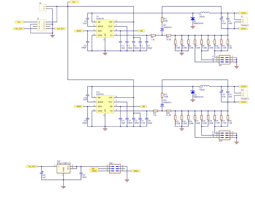
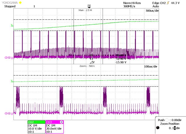
Bus voltage fluctuation during burst mode can affect light quality by causing flicker at low dimming levels in
PWM modes. This happens when the switching period and dimming pulse width are similar. In Figure 11, you
can see two oscillograms; green is the bus voltage, pink is the output current. On the left, the switching period
is similar to a dimming pulse of 1 percent, and as a result, the LED buck converter cannot regulate LED current
in one cycle, which results in flicker at the burst mode frequency. On the right, the switching period is ten times
shorter than the minimum dimming pulse; therefore, the LED current is much more precise, and the flicker level
is negligible.
If you consider PWM dimming using its calculated minimum frequency switching, select a much higher
switching period than the minimum dimming pulse. This will help to avoid or minimize the flicker level at
minimum dimming in burst mode.
Aplication Note 9 of 13 V 1.0
2021-01-29ILD8150 in tunable white and multichannel LED applications
Design hints
Figure 11 Hybrid dimming mode at bus voltage fluctuation. On the left – low switching frequency,
right – high switching frequency.
Comparative color temperature accuracy is important. Mismatching minimum currents may lead to different
light colors, different from dimming accuracy. If the second-stage channels are supplied from the same bus
voltage, having the same LED number and operating temperature, the mismatch will be minimized. Color
temperature accuracy, in this case, is related to dimming accuracy as an error between a linear dimming curve
and a straight line, as shown in Figure 12.
Figure 12 Comparative color temperature accuracy over dimming for tunable white application
It is much easier to achieve high color accuracy when bus voltage and LED voltages are similar, considering
only IC accuracy and component tolerances.
Aplication Note 10 of 13 V 1.0
2021-01-29ILD8150 in tunable white and multichannel LED applications
References for related documents and tunable white/dimming engines
4 References for related documents and tunable white/dimming
engines
[1] Infineon: “Application Note AN_1809_PL39_1810_124440 (Revision 1.1)”, 2019-01-23
(https://www.infineon.com/dgdl/Infineon-
ApplicationNote_reference_design_REF_ILD8150_DC_1.5A_LightingICs_LED_driver-ApplicationNotes-v01_00-
EN.pdf?fileId=5546d462689a790c0168c39bfda86810)
[2] Infineon: “Application Note AN_1907_PL39_1907_083934 (Revision 1.0)”, 2019-08-05
(https://www.infineon.com/dgdl/Infineon-
Reference_design_REF_ILD8150_DC_1.5A_high_frequency_operation-ApplicationNotes-v01_00-
EN.pdf?fileId=5546d4626d66c2b1016d73f768f820ae)
Aplication Note 11 of 13 V 1.0
2021-01-29ILD8150 in tunable white and multichannel LED applications
Revision history
Revision history
Document Date of release Description of changes
version
V 1.0 29-01-2021 First release
Aplication Note 12 of 13 V 1.0
2021-01-29Trademarks
All referenced product or service names and trademarks are the property of their respective owners.
IMPORTANT NOTICE
Edition 2021-01-29 The information contained in this application note is For further information on the product, technology,
given as a hint for the implementation of the product delivery terms and conditions and prices please
Published by only and shall in no event be regarded as a contact your nearest Infineon Technologies office
description or warranty of a certain functionality, (www.infineon.com).
Infineon Technologies AG condition or quality of the product. Before
81726 Munich, Germany implementation of the product, the recipient of this
application note must verify any function and other WARNINGS
technical information given herein in the real Due to technical requirements products may contain
© 2021 Infineon Technologies AG. application. Infineon Technologies hereby disclaims dangerous substances. For information on the types
any and all warranties and liabilities of any kind in question please contact your nearest Infineon
All Rights Reserved. (including without limitation warranties of non- Technologies office.
infringement of intellectual property rights of any
Do you have a question about this third party) with respect to any and all information
given in this application note. Except as otherwise explicitly approved by Infineon
document? Technologies in a written document signed by
authorized representatives of Infineon
Email: erratum@infineon.com The data contained in this document is exclusively Technologies, Infineon Technologies’ products may
intended for technically trained staff. It is the not be used in any applications where a failure of the
responsibility of customer’s technical departments product or any consequences of the use thereof can
Document reference to evaluate the suitability of the product for the reasonably be expected to result in personal injury.
AN_2004_PL39_2006_121319 intended application and the completeness of the
product information given in this document with
respect to such application.You can also read