Switching/dimming actuator 2x DALI Broadcast - Siemens ...
←
→
Page content transcription
If your browser does not render page correctly, please read the page content below
GAMMA instabus

Switching/dimming actuator 2x DALI Broadcast
N 525D11

                    Switching/dimming actuator N 525D11, 2x DALI Broadcast is used for switching and
                    dimming two independent DALI lines (channels). This device can also control the
                    brightness and color temperature of lamps at the same time.
                    ●  Broadcast control of electronic control gear (ECG) with 2 independent DALI lines
                       (channels)
                    ● Up to 20 devices can be connected to each channel.
                    ● Direct mode (switching and dimming) for a simple check of the installation
                    ● Display element for error messages of the DALI installation
                    Functions with configuration with ETS:
                    ● Extensive control, override and diagnostic functions for each channel
                    ● Configurable dimming curve and various fade times for optimal dimming
                    ● Independent color temperature control that is also integrated into scenes and
                       overrides
                    ● Control value input for analog values can be configured as an alternative to the
                       switching input
                    ● Integrated 8-bit scene control and assignment of each output to up to 8 scenes
                    ● Switching cycle counting with threshold monitoring for switching cycles
                    ● Counting of operating hours with threshold monitoring of operating hours

A6V11914216_en--a                                                                        Smart Infrastructure
2020-02-17                                                                                Building Products
Characteristics
Switching/dimming actuator N 525D11, 2x DALI Broadcast is a KNX device with two DALI
outputs (channels). Up to 20 devices can be connected per channel. Switching/dimming
actuator N 525D11, 2x DALI Broadcast is a rail-mounted device for installation in
distributions. For DALI, the electronics of the DALI devices are fed via the DALI bus line.
Hence, the device has an integrated power supply for AC 230 V for supplying the device
electronics and generating the DALI bus voltage for each channel.
The device is used to connect and control a group of dimmable lamps in parallel, e.g. if
individual communication with each individual DALI device is not necessary.
In addition, the device can record and transfer status and error messages of DALI lines but
not individual DALI devices.
The device can control the brightness of the lamps as well as the color temperature in
parallel (“tunable white”). The device can therefore be used in human-centric lighting
applications.
Functions
Building site function
The building site function provided ex-factory enables switching the building site lighting on
and off via bus wall switches and actuators, even if these devices have not yet been
commissioned with the Engineering Tool Software (ETS).
Direct mode
After installation, the individual channels of the device can be tested directly on the device.
Prior configuration via the software is not necessary for this.
In the delivery state, direct mode is activated without a time limit.
After configuration, direct mode is limited to the configured time limit.
Display and error messages
The device’s display shows the error codes of the error messages from DALI lines and
information on normal mode and direct mode. The display also shows error messages (even
with the factory settings).
The following error messages are displayed:
● F0: Lamps defective
● F4: External voltage on DALI line
● F5: Short circuit of DALI line
● F6: No ECG found
● "." (Dot in the bottom right corner): The application cannot be started
Communication objects are created for the individual error messages.
Resetting the device to factory settings
A very long push of the programming button of more than 20 seconds resets the device to its
factory settings. This is indicated by a uniform flashing of the programming LED for 8
seconds.
All configuration settings are deleted. The building site function of the delivery state is re-
activated.
Operating modes
Each output (channel) of the switching/dimming actuator may be set to one of the following
operating modes:
● Normal mode
● Timer mode
● Timer mode 2-fold
● Flashing
2
Smart Infrastructure A6V11914216_en--a
GAMMA instabus 2020-02-17Dimming curve
The dimming curve acts like a correction factor. Lamps can therefore be dimmed brighter or
darker in the medium dimming range, for example, to optimally adjust fluorescent lamps to
the dimming behavior of incandescent lamps.
The following settings are possible:
● Smooth 2: Curve (1)
● Smooth 1: Curve (2)
● Linear: Curve (3)
● Progressive 1: Curve (4) 6
● Progressive 2: Curve (5)
5
● Progressive 3: Curve (6)
Brightness
● User-defined: 4
3
With this setting the parameter card 2
“dimming curve user-defined” is 1
displayed. Here, the dimming curve can
be defined manually by entering up to
16 values for the x-axis (dimming value)
and y-axis (brightness).
Dimming value
Color temperature control
The color temperature control is defined in standard DALI IEC 62386, in chapter 209 “Color
Control.” The ECG is defined as device type 8. Device type 8 refers to color controllable
lights. The color temperature is measured in Kelvin (K).
Switching/dimming actuator N 525D11, 2x DALI Broadcast can control the color temperature
and brightness of ECG of device type 8.
The device can be used in human-centric lighting application because it can control the color
temperature of a DALI LED from warm white to cold white ("tunable white").
Human-centric lighting (HCL) expands the concept of biologically effective lighting with
holistic planning and covers the visual, emotional and biological effects of light. HCL
supports human health, well-being and performance in the long-term.
Control value input
As an alternative to the switching input, there is also a control value input for each channel.
The control value input can be used to implement analog values in switching on/off
commands. A threshold value can also be set.
The following datapoint types are possible:
● 5.001 percent (0 … 100 %)
● 5.010 counting impulses (0 … 255)
● 9.001 temperature °C
● 9.004 illuminance lx
● 9.021 current mA
● 9.024 output kW
● 14.056 output W
Timer functions
When configuring the device with ETS, two different timers and night mode can be
programmed. It is possible to set e.g. delayed switching on/off as well as a warning before
switching off occurs.
3
Smart Infrastructure A6V11914216_en--a
GAMMA instabus 2020-02-17Dimming
Two different dimming values are available for each channel.
In addition, a minimum and maximum dimming value can be set via a communication object.
In particular with LED and energy saving lamps, these parameters can be used to optimize
dimming behavior in the lower dimming range.
The communication object “global dimming” can be used to temporarily or permanently limit
the maximum dimming value, e.g. to save energy.
Central switching
The “central switching” function contains an object for each channel. With this object, switch
telegrams are received which are then sent to the associated output using a different time
function than the one for the communication object “switching.”
Error messages
Display and error messages [➙ 2]
8-bit scene control
Using 8-bit scene control, current brightness values or switching states can be assigned to a
scene and activated again later through the scene.
Overrides
Up to seven different override function blocks can be activated via ETS to override the
automation functions:
● Manual override (ON)
● Permanent OFF
● Lock
● Central override
● User-defined override function
● Forced control
Logic operations
This parameter can be used, if necessary, to add an additional switching object “logic
operation 1” to the switching of the output via a logic operation of the switching object. The
logic operation object is not subject to any time delay, i.e. the logic operation is always in
effect immediately. The following logic operations are possible:
● AND
● OR
● XOR
● FILTER
● TRIGGER
Switch cycle and operating hours count
To monitor use, the right configuration makes it possible to count and display the switch
cycles and operating hours of the device.
Behavior on mains voltage failure/recovery
In case of a mains voltage failure, the current status and other values for each output are
permanently saved so that they can be restored on mains voltage recovery.
On mains voltage recovery, the configured actions are executed and, if applicable, new
statuses are reported.
4
Smart Infrastructure A6V11914216_en--a
GAMMA instabus 2020-02-17Behavior on unloading the application program
After “unloading” the application program with the ETS, the unloaded device has no
functions.
If the programming button is pushed for more than 20 seconds, the device is reset to its
factory settings.
Schematic design of a dimming channel
The following schema illustrates the listed functions in a logical overview.
Send status value
Control value 1
0
Switching
Control Value
Input
Logic operation 1/2 Logic operation 1/2
Control functions
t t
Central switching
Normal mode/flashing Normal mode/
flashing
8-bit
8-bit scene
scene control
Dimming Flashing 0 1
Dimming value 1/2
Night mode 0 1
Timer period
day mode Timer (day) Normal
Flashing
1-fold/2-fold mode
Timer
Timer period (night)
night mode
Override 1 – 2 Override 1 – 2 Status override 1 – 2
functions
Override
Global dimming Global dimming
Override 3 – 7 Override 3 – 7 Status override 3 – 7
Direct operation lock Direct operation Status direct operation
Min./max. Dimming value Min./Max. Dimming value
Diagnosis functions
Status Status switching
Status dimming value
Number of Status number
switch cycles of switching cycles
Operating hours Status operating hours
Schematic design of a dimming channel
5
Smart Infrastructure A6V11914216_en--a
GAMMA instabus 2020-02-17Switching
8-bit
Control functions
8-bit scene
scene control
Dim color
temperature
Color temperature value
Override 1 – 2 Override 1 – 2
functions
Override
Central color
Central color temperature
temperature
Override 3 – 7 Override 3 – 7
Min./max. Color
Min./max. Color
Diagnosis functions
temperature
Status Status of color
temperature value
Flow chart for color temperature control
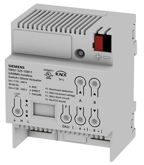
Technology
Position and function of the operating and display elements
1
2
7
3
6
5 4
User interface with operating and display elements
6
Smart Infrastructure A6V11914216_en--a
GAMMA instabus 2020-02-17Pos. Operating or display elements Function
1 Programming LED (red), Short push of button (< 2 s):
Programming button ● Activate programming mode, display status (LED
on = active).
Very long push of button (> 20 s):
● Reset to factory settings (after 20 s, the LED starts
flashing for about 8 s).
2 Button: Switch on, dim brighter, channel A or Short push of button (< 1 s):
B in direct mode ● Switch on channel A or B and
● activate direct mode for channel A or B.
Long push of button (> 1 s):
● Dim channel A or B brighter and
● activate direct mode for channel A or B.
If direct mode is activated, a “d” is shown on the display.
3 Button: Switch off, dim darker, channel A or B Short push of button (< 1 s):
in direct mode ● Switch off channel A or B and
● activate direct mode for channel A or B.
Long push of button (> 1 s):
● Dim channel A or B darker and
● activate direct mode for channel A or B.
4 Button: Show error codes If an error occurs on a channel, the first character
shown on the display is an “F” (failure). In addition, the
LED of the respective channel flashes in short intervals.
Short push of button (< 1 s):
● Show error code.
● In case of several errors, push the button several
times until “Fb” (failure in bus operation) or “Fd”
(failure in direct operation) is displayed again.
5 Display Shows information on the device and errors.
6 Button: Deactivate direct mode Short push of button (< 1 s):
● Deactivate direct mode for all channels.
Keep pushing the button and briefly push the button
‘Switch on, dim brighter’ or ‘Switch off, dim darker’
channel A or channel B:
● deactivate direct mode for channel A or B.
7 LED (red), once each for channel A and Display switching state (On/Off) of the respective
channel B channel.
● LED lit: Channel switched on (dimming value > 0).
● LED off: Channel switched off (dimming value = 0).
● LED lights up with brief interruptions: Channel
switched on in direct mode.
● LED flashing: Channel switched off in direct mode.
Type overview
Type Description Article number KNX PL-Link
N 525D11 Switching/dimming 5WG1525-1DB11 Yes
actuator, 2x DALI
Broadcast
Version of the Engineering Tool Software
Application Version
Engineering Tool Software (ETS) ETS 5 or above
7
Smart Infrastructure A6V11914216_en--a
GAMMA instabus 2020-02-17Product documentation and support
Disposal
Defective devices can be returned to the appropriate sales office with a return delivery note.
To do this, contact support: Product documentation and support [➙ 8]
Product documentation
Documents belonging to the product, such as operating and assembly instructions,
application description, product database, additional software and CE declarations can be
downloaded from the following website:
http://www.siemens.com/gamma-td
Frequently asked questions
For frequently asked questions regarding the product and their solutions, see:
https://support.industry.siemens.com/cs/ww/en/ps/faq
FAQ
Support
Contact details for additional questions relating to the product:
Tel.: +49 911 895-7222
Fax: +49 911 895-7223
Email: support.automation@siemens.com
http://www.siemens.com/supportrequest
?
8
Smart Infrastructure A6V11914216_en--a
GAMMA instabus 2020-02-17Notes
Security
CAUTION
National safety regulations
Failure to comply with national safety regulations may result in personal injury and property
damage.
● Observe national provisions and comply with the appropriate safety regulations.
WARNING
● The device should only be installed and put into operation by a certified electrician.
● Ensure that the device can be activated.
● Do not open the casing of the device.
● Secure the phase with a B6 or C6 line protection switch.
Installation
Switching/dimming actuator N 525D11, 2x DALI Broadcast can be used for fixed installations
in interior spaces, for installations in dry locations, within distribution boards or small casings
on DIN rails EN 60715-TH35.
Commissioning
Connecting the power supply
0.5 x 3.5 mm
2a
1
10...11 mm
2b
Connecting the power supply
Cu
0.5 ... 2.5 mm²
AWG 20 (0.75 mm²) ... AWG 12 (3.3 mm²) ...
9
Smart Infrastructure A6V11914216_en--a
GAMMA instabus 2020-02-17Connecting DALI
0.5 x 3.5 mm
2a
1
10...11 mm
2b
Connecting DALI
Cu
0.5 ... 2.5 mm²
AWG 20 (0.75 mm²) ... AWG 12 (3.3 mm²) ...
Connecting KNX
RED + BLACK -
2
1
3
5...6 mm
Connecting KNX
Cu
0.6 ... 0.8 mm
AWG 20 (0.75 mm²) ... AWG 18 (1.0 mm²) ...
10
Smart Infrastructure A6V11914216_en--a
GAMMA instabus 2020-02-17KNX test
This test can be used to check whether the bus connection cable is connected with the
correct polarity and whether device is supplied with bus voltage.
2
3 sec 1
LED OFF
LED ON
6
L|N|PE 4 5
ON
3 > 20 s RESETTechnical data
Power supply
KNX bus voltage DC 24 V (DC 21...30 V)
KNX power consumption 5 mA
Power loss (internal consumption) 1.6 W
Operating voltage
Nominal value 230 V
Rated value AC 110 V...240 V
Rated value DC 120 V...240 V
Inputs/outputs
Power connection 3-pole (earth, N, L)
DALI outputs as per IEC 62386 2 channels with max. 20 DALI ECG per channel
(max. 2 mA each)
with > 8 kOhm input impedance
DALI power supply per channel approx. DC 19 V, potential-free, short circuit-proof
max. power: lmax = 250 mA
max. guaranteed power: lmax = 40 mA
DALI line length for copper at 25 °C 2.5 mm² (AWG 14) max. 300 m (328 yd)
1.5 mm² (AWG 16) max. 300 m (328 yd)
1.0 mm² (AWG 18) max. 224 m (225 yd)
The power loop resistance for each connected ECG
must not be more than 10 Ohm.
Connections
Plug terminals for mains voltage and DALI interface, Permissible conductor cross-section
bare wire length 10...11 mm* (0.39...0.43 in) 0.5...2.5 mm² solid
0.5...2.5 mm² stranded
0.5...2.5 mm² fine-stranded, untreated
AWG 20 (0.75 mm²) – AWG 12 (3.3 mm²)
solid, stranded
KNX bus Bus terminal block
* The mains supply line to the device must be protected by a circuit breaker of characteristic
B or C for a max. rated current of 6 A.
Physical specifications
Housing material Plastic
Dimensions 4 TE (= 18 mm) Dimensions [➙ 13]
Weight (device) approx. 180 g (0.3968 lb)
Fire load 4 MJ
Environmental conditions
Ambient temperature in operation -5 °C...+45 °C (23 °F…113 °F)
Storage temperature -20 °C...+70 °C (-4 °F…158 °F)
Transport temperature -25 °C...+70 °C (-13 °F…158 °F)
Relative humidity 5 %...90 %
(non-condensing)
Climatic resistance EN 50491-2
Environmental rating EN 60721-3-3 class 3k5
12
Smart Infrastructure A6V11914216_en--a
GAMMA instabus 2020-02-17Protection settings
Degree of pollution (according to IEC 60664-1) 2
Overvoltage category (according to IEC 60664-1) III
Protection type IP IP20
Electrical safety, bus Safety extra low voltage SELV DC 24 V
Electrical safety, device fulfills EN 50428
EMC requirements, device complies with EN 50428
Reliability
Failure rate (at 40°C) 419 fit
Dimensions
55 mm
[2.17 in]
44 mm
[1.73 in]
[3.54 in]
90 mm
72 mm 61 mm
[2.84 in] [2.40 in]
Dimensions
13
Smart Infrastructure A6V11914216_en--a
GAMMA instabus 2020-02-17Connection example
The following connection example shows the connection of dimmable electronic control gear
(ECG Dynamic) with a DALI interface to channels A and B.
+ 24V DC
-
Connection example
Issued by © Siemens Switzerland Ltd, 2020
Siemens Switzerland Ltd Technical specifications and availability subject to change without notice.
Smart Infrastructure
Global Headquarters
Theilerstrasse 1a
CH-6300 Zug
Tel. +41 58 724 2424
www.siemens.com/buildingtechnologies
14
Smart Infrastructure A6V11914216_en--a
GAMMA instabus 2020-02-17
Document ID A6V11914216_en--a Technical product information
Edition 2020-02-17You can also read