Construction of a Mobile Frequency Modulation Transmitter
←
→
Page content transcription
If your browser does not render page correctly, please read the page content below
IOP Conference Series: Earth and Environmental Science

PAPER • OPEN ACCESS

Construction of a Mobile Frequency Modulation Transmitter
To cite this article: Mojisola R. Usikalu et al 2021 IOP Conf. Ser.: Earth Environ. Sci. 655 012034

View the article online for updates and enhancements.

                                This content was downloaded from IP address 46.4.80.155 on 13/03/2021 at 04:27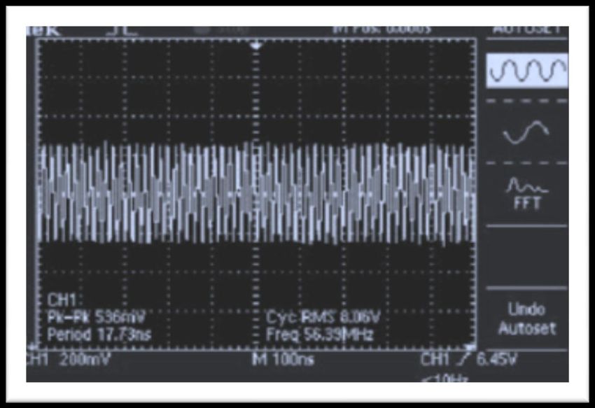
4th International Conference on Science and Sustainable Development (ICSSD 2020)            IOP Publishing
IOP Conf. Series: Earth and Environmental Science 655 (2021) 012034     doi:10.1088/1755-1315/655/1/012034

Construction of a Mobile Frequency Modulation Transmitter

                     Mojisola R. Usikalu, Fumbi T. Oyeniran, Williams A. Ayara, Idowu I.
                     Babarimisa and Leke N. Obafemi
                     Department of Physics, Covenant University, Ota, Ogun State, Nigeria

                     moji.usikalu@covenantuniversity.edu.ng

                      Abstract. A Frequency Modulation (FM) transmitter is an electronic device that produces radio waves
                      with the aid of an antenna. The transmitter generates radio frequency alternating current, that is applied to
                      the antenna. When the antenna is excited by the alternating current, the antenna begins to radiate radio
                      waves by varying the frequency of the radio signal. The transmitter is a Very High Frequency (VHF)
                      Colpitts oscillator capable of transmitting sound to standard FM receiver fitted with a capacitor
                      microphone which picks weak sound signals. This design was achieved using: transistors, resistors,
                      inductors and capacitors. A transmission frequency of ± 5% 100 MHz was used and transmitted up to a
                      distance of 5 metres. The testing of the transmitter was carried out by powering it using a 9 V DC battery
                      and tuning a suitable FM receiver to the transmission frequency of the constructed transmitter. A
                      transmission distance of 5 metres was achieved therefore making it possible to use the transmitter as a
                      portable cordless microphone used for public address (P.A.) systems. The achieved fixed frequency of
                      transmission 56.4 MHz, away from all other radio stations transmission frequencies. This gives the best
                      range and with the least of interferences. With increased power, the range can easily be extended.
                      Keywords: Transmitter, Antenna, Frequency, Modulation, Receiver, Radio-waves

1. Introduction
FM is a technique used for wireless transmission of data where the frequency of a carrier signal is
changed in proportion to the audio signal [1]. Both the carrier amplitude and the associated power of
the modulated wave are kept constant.Radio technology is always needed to meet the needs of man as
it is readily deployed in: communication, surveillance, aviation, and transportation, just to mention a
few. [2].This article describes the construction of a FM transmitter for quality audio transmission. The
first radio transmitter (Hertizian Oscillator) was made by Heinrich Hertz in 1887, and Edwin
Armstrong invented practical FM transmission in 1933 [2]. Radio transmission is accomplished with
the aid of electrical resonance when the frequency of the receiver is equal to the frequency emanating
from the transmitter. FM band is subjected to less distortion compared to those of Amplitude
Modulation (AM) band, (where the amplitude of the carrier signal is varied in proportion to the
instantaneous amplitude of the data signal) and Short Wave (SW) bands [3]. FM technology plays a
vital role in preserving the quality of the audio signal from the source to the receiver since it has more
excellent Signal-to-Noise Ratio (SNR) compared to an equal power AM.
Modulation is the process of superimposing data contained in a lower frequency signal into higher
frequency carrier signal. The basic parameters of a signal, i.e., amplitude, frequency, and phase can be
varied to give rise to a modulated signal of the said parameter. For this construction, the frequency of
the signal was varied. Hence frequency modulation was used. The modulation of signal is necessary
for efficient radiation and reception of radio signals which enhances comprehensive coverage or
broader operating range [4, 5]. The AM was not considered due to its limitations which include: noisy
              Content from this work may be used under the terms of the Creative Commons Attribution 3.0 licence. Any further distribution
              of this work must maintain attribution to the author(s) and the title of the work, journal citation and DOI.
Published under licence by IOP Publishing Ltd                          1
4th International Conference on Science and Sustainable Development (ICSSD 2020)            IOP Publishing
IOP Conf. Series: Earth and Environmental Science 655 (2021) 012034     doi:10.1088/1755-1315/655/1/012034

reception, low efficiency, small operating range, and lack of audio quality occasioned by constraints
on the allocated frequency spectrum of about 10 kHz [5]. In order to receive the broadcast, the process
of demodulation helps to recover (separate) the data signal from the modulated wave at the receiver
end. The recovered data signal is then amplified and fed to a speaker for conversion to sound wherein
the initial quality at the production stage is essentially preserved.

2. Methodology
Audio (pre-amplifier) was used for the amplification of the weak audio signal from the microphone,
Colpitts Oscillator was used for the generation of the sinusoidal carrier signal, and a Direct Current
(DC) 9 Vdc battery was used to provide DC power [6 – 8]. The principle of operation involved noise
rejection via FM, pre-emphasis (special boosting of high frequencies) at the transmitter stage and de-
emphasis at the receiver end [2]. The output at a receiver can only be affected by a noise signal
frequency only if it is within the receiver’s bandpass. Noise rejection is achieved by ensuring that that
peak amplitude is twice as great as the signal. The provided guard band in FM makes it possible to
reduce adjacent channel interference. Applying amplitude limiters in the FM receiver creates an
effective co-channel interference-capture effect as the relatively weak interfering signal from another
transmitter is effectively attenuated. At the transmitter’s end, special equalization process and pre-
emphasis are used to minimize the level of frequency noise (i.e., hiss) during transmission. At the
receiver end, an equal but opposite equalization process, de-emphasis is used to reduce high frequency
noise. This second process is called “compensate for the limited dynamic range of radio transmission”
[9, 10]. The circuit diagram of a low-cost mobile FM transmitter is shown in Figure 1.

Figure 1: The circuit diagram of a low cost mobile FM transmitter.

The various component values were carefully determined in order to achieve a functional device at
98.1 MHz frequency of operation. The transmitter construction consists of the power supply unit,
powered by a 9 Vdc battery, the audio pre-amplifier unit constructed with a NPN transistor of
common-emitter (CE) configuration, the power amplifier unit to amplify the carrier signal built with a
NPN transistor of CE configuration. The RF oscillator unit for the production of the carrier wave was
fabricated using a Colpitts Oscillator followed by the antenna unit. A single pole antenna was
employed is for transmission of FM signal through space.

                                                     2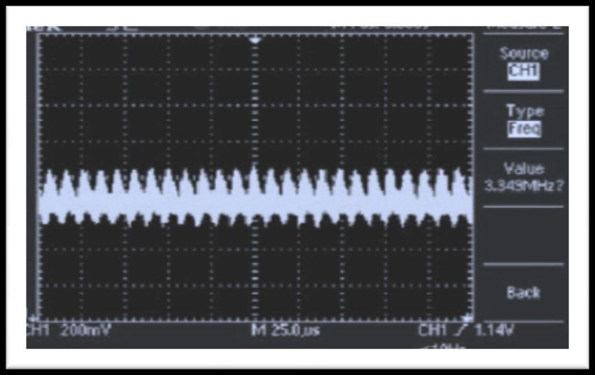
4th International Conference on Science and Sustainable Development (ICSSD 2020) IOP Publishing
IOP Conf. Series: Earth and Environmental Science 655 (2021) 012034 doi:10.1088/1755-1315/655/1/012034
The microphone picks the audio signal and feeds it into the pre-amplifier, which then amplifies the
weak audio signal and feeds same to the power amplifier. The power amplifier output is fed to the RF
oscillator where the carrier signal is generated and frequency modulation is performed. Afterwards,
the RF oscillator feeds the antenna for the propagation of the FM signal into space. The electret
microphone was used because of its high sensitivity due to its stable dielectric material in conjunction
with the embedded electric dipole moment that is static as a result of the in built high resistance. In
Figure 1, the 100 K resistor limits the current flow. For the pre-amplifier, the power amplifier and
oscillator stages, NPN transistors 2N3904 were used due to its general-purpose amplifying and
switching characteristics [11]. A single-pole antenna was incorporated because of the intended
portability of the device. A 9 Vdc battery powered the circuit to supply steady current. As soon as the
circuit was tested working properly on a breadboard, a printed circuit was made using a Vero board
and all components affixed and packaged in an improvised polyvinyl casing. The complete
constructed device is shown in Figure 2.
Figure 2: Showing image of the complete work
3. Results and Discussion
The waveform in Figure 3 shows the result before the oscillation and modulation process with a
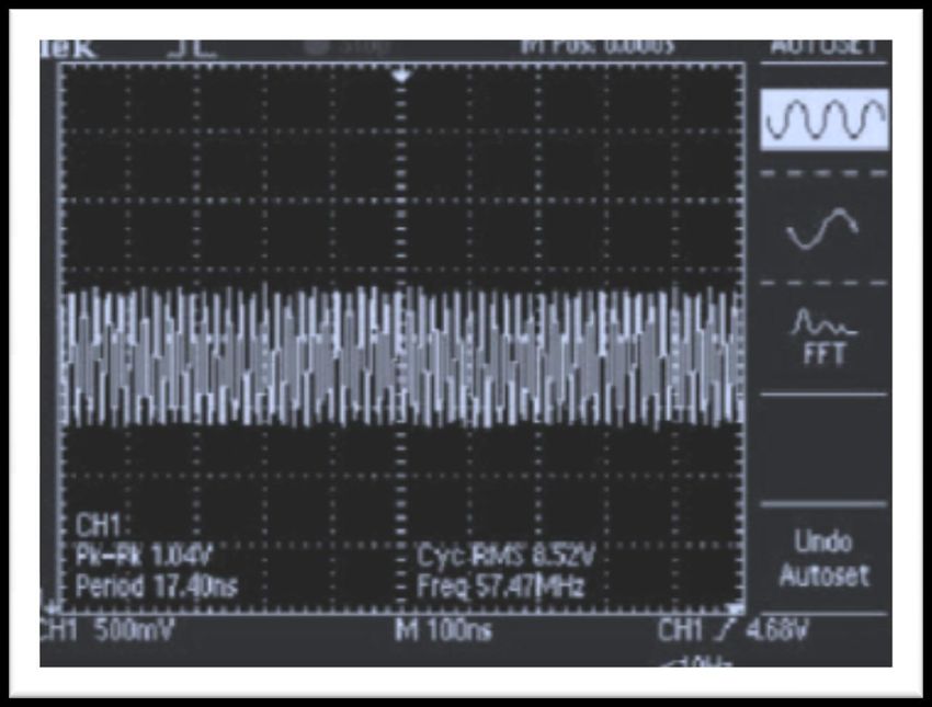
frequency value of 3.343 MHz. While Figure 4 shows the frequency after the amplification process.
The attained frequency at this point was 56.39 MHz, though less than the theoretically expected value
of 87.5 MHz. A number of factors may have caused this reduced frequency level, notably the source
of power and the variation in the value of capacitor C 4 and inductor L1 used for the construction. The
resulting waveform of the output of the pre-amplifier circuit (Figure 5) is in accordance with what a
typical Frequency Modulation waveform should look like. It was found that the carrier frequency
varies with the magnitude variations of the modulating signal. The carrier frequency was made to
fluctuate according to the modulating signal. Based on the result, the output frequency of the pre-
amplifier circuit was found to be low. The output is measured at inductor L1, where it acts as an
antenna for this FM telephone transmitter circuit.
3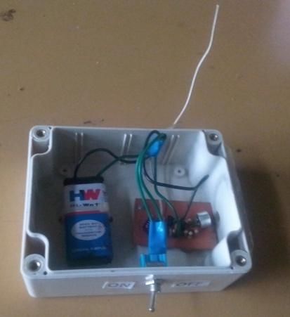
4th International Conference on Science and Sustainable Development (ICSSD 2020)            IOP Publishing
IOP Conf. Series: Earth and Environmental Science 655 (2021) 012034     doi:10.1088/1755-1315/655/1/012034

Figure 3: Waveform before pre-amplification

Figure 4: Waveform at the output of pre-amplifier

                                                     4
4th International Conference on Science and Sustainable Development (ICSSD 2020) IOP Publishing
IOP Conf. Series: Earth and Environmental Science 655 (2021) 012034 doi:10.1088/1755-1315/655/1/012034
Figure 5: Waveform at output of oscillator circuit
4. Conclusion
The constructed FM transmitter was tested and found to work within 5 metre distance with a
frequency range between 55.0 and 56.4 MHz. A greater amount of stability in the reception with a
minimal distortion was observed at 56.4 MHz frequency. Observation further revealed that the
transmitter performed better at the same frequency when power from a step-down transformer assisted
DC regulated power supply. Therefore, for optimal performance a regulated DC operated from the
mains will be preferable.
Acknowledgments
The authors acknowledged the support of Covenant University for the financial support for the
publication of the study.
References
1. Chen, D. (2002). Design and Construction of FM Transmitter and Receiver. Dissertion
Abstract International: Science and Engineering.1:45-49.
2. Horowitz, L., and Hill, W. (1989) The Art of Electronics (2nd edition).London: Cambridge
University Press. 297-300.
3. Louis, E. (2008). Priciples of Electronic communication systems.London: McGraw-Hill
Education, 787.
54th International Conference on Science and Sustainable Development (ICSSD 2020) IOP Publishing
IOP Conf. Series: Earth and Environmental Science 655 (2021) 012034 doi:10.1088/1755-1315/655/1/012034
4. Ackermann, J. (2013).TARR: Tomorrow’s Ham radio technology today. British Jornal for
History of Science 2(1): 100-120.
5. Atti, L. (2007). Audio Signal Processing and Coding. U.S.A: John Wiley Interscience, 464p.
6. Usikalu M. R, Isaac E. G, Olawole C. O, Abodunrin T. J and Kayode O. T (2019) Design and
construction of solar powered fabric dryer, International Journal of Mechanical and
Production Engineering Research and Development, 9(6): 139-148
7. Ayara W. A, Omotosho T. V, Usikalu M. R, Singh M. S, Suparta W. 2017. Development of a
solar charged laboratory bench power supply, Journal of Physics: Conference Series 852 (1),
012044
8. Usikalu M. R, Shittu A. H and Obafemi L. N (2018) Construction of an intelligent and
efficient light control system, International Journal of Mechanical and Production
Engineering Research and Development (IJMPERD), 8(4): 1057-1066
9. Ezeorah, C. (2009). Wireless system operation. Selection and operation of wireless
Microphone Systems 23-26.
10. Floyd, T. (2004). Electronic Devices: conventional current version.(9th edition). London:
Pearson Educational Publications, 976p.
11. Kleitz, W. (2005). Digital Electronics: A Practical Approach. (7th edition). London:
Cambridge University Press 500-512.
6You can also read