A fuzzy controller for two energy storage management system in electric bicycle
←
→
Page content transcription
If your browser does not render page correctly, please read the page content below

IOP Conference Series: Materials Science and Engineering

PAPER • OPEN ACCESS

A fuzzy controller for two energy storage management system in electric
bicycle
To cite this article: P. Pera et al 2021 IOP Conf. Ser.: Mater. Sci. Eng. 1137 012015

View the article online for updates and enhancements.

 This content was downloaded from IP address 46.4.80.155 on 10/09/2021 at 13:19
The11th International Conference on Mechanical Engineering (TSME-ICOME 2020) IOP Publishing
IOP Conf. Series: Materials Science and Engineering 1137 (2021) 012015 doi:10.1088/1757-899X/1137/1/012015

A fuzzy controller for two energy storage management system
in electric bicycle

 P. Pera 1, M. Masomtob2, W. Intano1 and A. Kaewpradap1*
 1
 Department of Mechanical Engineering, King Mongkut’s University of Technology
 Thonburi, Bangkok, 10140, Thailand
 2
 National Energy and Technology Center (ENTEC), National Science and Technology
 Development Agency (NSTDA), Pathum Thani, 12120, Thailand

 * Corresponding Author: amornrat.kae@mail.kmutt.ac.th

 Abstract
 This paper presents an energy management system for an electric bicycle that runs in
 local community in Thailand. Fuzzy logic technique is applied in this system to control
 supercapacitor and battery management according to the demand of load power.
 The load of the electric bicycle depends on speed of each driving cycle. Mamdani-based
 fuzzy logic controller is selected to control the ratio of output between supercapacitor
 and lead acid battery. Fuzzy logic controller aims to reduce battery usage during peak
 current occured from the electric bicycle and passes speed bump in order to extend the
 lead acid battery life time.

 Keywords: Fuzzy logic control, Energy management system, Speed bump, Electric
 bicycle.

1. Introduction
In the last few years, Plug-in Hybrid Electric Vehicle (PHEV) and Battery Electric Vehicle (BEV) in
Thailand has become more popular due to its zero emission [1]. The number of registered cars
accumulatively increase from 7705 to 156,038 cars during of 2015-2019 [2]. Electric bicycle is one type
of EV that has become more popular to use in city area. It is used to replace motorcycle and bicycle for
people who travel less than 20 km. People prefer to use electric bicycle because no driving license
needed, ecofriendly, easy to maintenance and the price is cheaper than an internal combustion
motorcycle. For the electric bicycle to become cheap and easy to maintenance lead acid battery is used
as energy storage. Government launches many policies such as zero tax for Electric Vehicle (EV)
manufactured in Thailand, 100,000 baht subsidy for users who buy EV [3], and support to industries
and researches to create more EV.
 One of the most important research topics is the development of energy management systems
for battery. Energy management system is one of the most essential systems in EV because battery is
the most important part to make EV running. The better energy management system could extend the
driving range of the EV. Due to the limitation of the battery Hybrid Energy Storage System (HESS) as
shown in Figure 1. This system is applied to the system to help increase driving range and extend battery
lifetime [4].

 Content from this work may be used under the terms of the Creative Commons Attribution 3.0 licence. Any further distribution
 of this work must maintain attribution to the author(s) and the title of the work, journal citation and DOI.
Published under licence by IOP Publishing Ltd 1
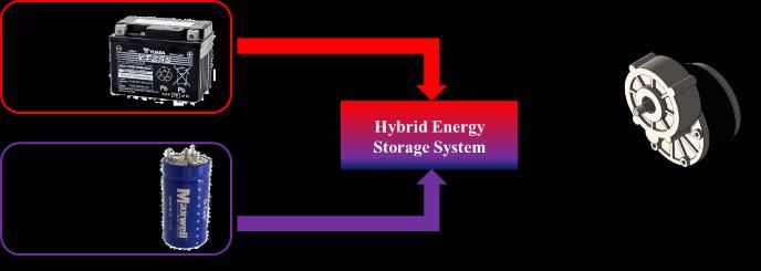
The11th International Conference on Mechanical Engineering (TSME-ICOME 2020) IOP Publishing
IOP Conf. Series: Materials Science and Engineering 1137 (2021) 012015 doi:10.1088/1757-899X/1137/1/012015

 The previous research of HESS is used to manage two energy sources i.e., fuel and battery.
Since EV has been more popular the manufacturers and researchers want to change from fuel to battery
and other types of storage system. The problem of pure EV is car acceleration required high power
battery causes insufficient energy for the battery to distribute power to motor. On the other hand, only
the battery is not enough for the EV. As the result of, the present studies try to develop a HESS which
uses supercapacitor to improve insufficient energy [5]. Supercapacitor is a new type of energy storage
that can distribute high power with a rapid charge and discharge rated [6]. HESS between supercapacitor
and battery is importance to use logic control and design the power distribution at different situation [5].
There are many types of logic control for HESS. Simple frequency decoupling technique which
separates power demand by using low pass and high pass filter. Supercapacitor is applied for transients
and peak loads [7]. The load can be classified by low and high frequency. The control method for energy
management system in solar panel –battery super capacitor hybrid energy system in solar car is utilized
by if-clause algorithm [8]. Fuzzy is a Linguistic language that represents the human words or feeling
into value that computer understands. Therefore, fuzzy is not commonly use with HESS. The research
about Fuzzy usually uses with air-condition and electric water heater [9][10]. It is found that the fuzzy
algorithm can be applied for energy management for EV. Thus, this research focuses on fuzzy logic in
HESS in EV of supercapacitor and battery.
 Electric bicycle is used in as a parameter to build fuzzy logic control. However, this logic
control can be applied for EV in the future. The influence factors in fuzzy logic control are the following:
First, the effect of the ratio between battery and supercapacitor. Then, the speed differentiation.
This research is to study on experiment in MATLAB Simulink. Bangkok Driving Cycle and speed bump
to evaluate the fuzzy logic control algorithm[11]. For extension of the lead acid battery lifetime.

 Figure 1. Hybrid Energy Storage Management System.
2. Nomenclature
A Frontal area of vehicle (m2)
α Gain
 Drag coefficient
F Force (N)
 Tractive force (N)
 Gravity force (N)
 Mass (kg)
P Electric power (W)
 Air density (kg/m3)
 Aerodynamic drag resistance (N)

 2
The11th International Conference on Mechanical Engineering (TSME-ICOME 2020) IOP Publishing
IOP Conf. Series: Materials Science and Engineering 1137 (2021) 012015 doi:10.1088/1757-899X/1137/1/012015

 Inertial resistance (N)
 Grade resistance (N)

 Rolling resistance (N)
 Rolling resistance coefficient
v Speed vehicles (m/s)

3. Methodology
3.1 Hybrid Energy Storage System (HESS)
HESS in this system uses fuzzy logic control to evaluate the amount of the power load from the electric
bike. Battery and Supercapacitor are input for fuzzy that can distribute energy depend on load. Power
load is input for fuzzy but demand energy.

 Hybrid Energy Storage System (HESS)

 V bat
 Battery
 Supercapacitor
 Discharge
 Vsc
 Ratio between
 Supercapacitor Fuzzy Logic Battery &
 Supercapacitor Battery
 Control Discharge
 Power Load

 Figure 2. Overview of HESS system.
3.2 Energy consumption [12]
The total energy consumption can be derived by total force and vehicle speed as shown in Equation (1)

 = · (1)
The electric power can be obtained from by total resistance force and vehicle speed as illustrated in
Equation (2)
 = (R a + R r + + ) ∙ (2)

The energy consumption in Equation (1) can be calculated by total force as shown in Equation (3)
 = + + + (3)

 3
The11th International Conference on Mechanical Engineering (TSME-ICOME 2020) IOP Publishing
IOP Conf. Series: Materials Science and Engineering 1137 (2021) 012015 doi:10.1088/1757-899X/1137/1/012015

The total force act on bicycle is shown in Figure (3).

 Figure 3. Forces acting on bicycle.
 Aerodynamic drag resistance is the air resistance during the vehicle moving which is
calculated by the Equation (4). The 1.1 of drag coefficient ( ) is applied with 1.1839 kg/m3 of air
density in this experiment.
 1
 = ∙ ∙ ∙ 2 (4)
 2

 Rolling resistance is the resistance occurring on the wheel turns on the surface which related to
the weight of the vehicle as shown in Equation (5). The 0.04 of rolling resistance coefficient tire turns
on asphalt road, 90 kg of mass for electric bike and driver [8]
 = ∙ ∙ ∙ (5)
 Grade resistance is the resistance that occurs when the vehicle travels up or down the slope.
As shown in Equation (6). In this experiment the vehicle runs on plain path which have less gradient
even the speed reduces. The road grade ( ) is almost zero degree thus the grade resistance is neglected.
 = ∙ ∙ (6)

 4
The11th International Conference on Mechanical Engineering (TSME-ICOME 2020) IOP Publishing
IOP Conf. Series: Materials Science and Engineering 1137 (2021) 012015 doi:10.1088/1757-899X/1137/1/012015

3.3 Fuzzy logic control
The first step of Fuzzy Logic Control (FLC) is to transform linguistic language into computer language
as an input for FLC and make a decision with its own algorithm that the user designs to get the desirable
output, for example in the Figure 4 the temperature control of the water. Normal control can only
separate on and off the heater as 1 and 0. However FLC separates the input into more detail i.e., cold,
cool, nominal, warm and hot. Then substitute all this feeling into the computer language.

 Traditional logic
 Cold Hot

 Fuzzy logic
 Cold Cool Nominal Warm Hot

 Figure 4. Comparison of water temperature control[13].
 For the algorithm of design part, the all-output responses from each input are needed to know
for design of the control algorithm based on real data as shown in Figure 5. However, the unknown
output result from FLC algorithm by using the function design fuzzy in MATLAB then importing the
fuzzy file into the control algorithm.

 Figure 5 Fuzzy logic control design in MATLAB.
3.4 Bangkok driving cycle
Bangkok driving cycle is the standard for test of the vehicle fuel consumption and power consumption
in Thailand. Bangkok driving cycle consists of 6 phases as shown in Figure 6 and 7. As the previous
research, this driving cycle was applied for study of motorcycle. Thus, the Bangkok driving cycle is
expected to apply for the experiment of electric bicycle. Following the Bangkok driving cycle the speed
is calibrated by gain of 0.3 to comply with electric bicycle. The speed is used to calculate the power
consumption of electric bicycle for this driving cycle based on the theory of bicycle model.

 5
The11th International Conference on Mechanical Engineering (TSME-ICOME 2020) IOP Publishing
IOP Conf. Series: Materials Science and Engineering 1137 (2021) 012015 doi:10.1088/1757-899X/1137/1/012015

 Figure 6. Bangkok driving cycle phase 1,2,6 [11].

 Figure 7. Bangkok driving cycle phase 3,4,5 [11].
 The relation of speed according to the Bangkok driving cycle is shown in Figure 8. In case of
driving cycle is applied without supercapacitor, the battery has to supply all the power for the load.

 6
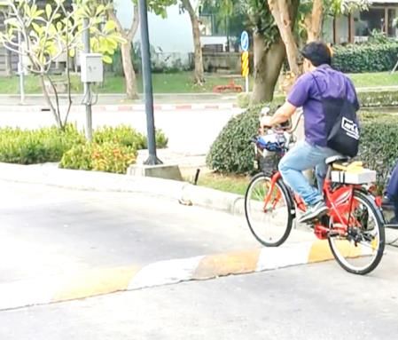
The11th International Conference on Mechanical Engineering (TSME-ICOME 2020) IOP Publishing
IOP Conf. Series: Materials Science and Engineering 1137 (2021) 012015 doi:10.1088/1757-899X/1137/1/012015

 Bangkok driving cycle
 Speed (km/hr)
 Power (w)
 Torque (N)

 Time (s)
 Figure 8. Power consumption on Bangkok driving cycle.

 Table 1. The simulation parameters for electric bicycle.
 Parameter Value Unit
 Cross Section Area ( ) 0.8×0.5×1.6 2
 Air Density ( ) 1.1839 25℃
 Drag Coefficient ( ) 1.1
 Mass ( ) 90 kg
 Gravity Force ( ) 9.81 2 /
 Rolling Friction Force ( ) 0.018 at dry asphalt
 Slope (∆) 0
 Angle ∆ rad
 180 ∙

3.5 Specification of electric bicycle
 Table 2. Specification of electric bicycle.
 Specifications
 Motor DC Gear Motor SNK 24 V 250
 W

 Battery Battery 6 lead acid Yuasa
 YTZ5s 2 series then 3 parallel
 24 V

 Supercapacitor 350 F, Nominal voltage 2.7 V, 6
 series

 Speed bump characteristic is collected by the experiment with variable parameter in this study.
 The illustration of actual experiment is represented in Figure 9.

 7
The11th International Conference on Mechanical Engineering (TSME-ICOME 2020) IOP Publishing
IOP Conf. Series: Materials Science and Engineering 1137 (2021) 012015 doi:10.1088/1757-899X/1137/1/012015

 Figure 9. Actual experiment of speed bump.
3.6 Fuzzy algorithm
The fuzzy algorithm is designed base on real experiment. The maximum power load, steady load battery
and supercapacitor characteristic are used to design the fuzzy input and output as shown in Figure 10
(a) and Figure 10(b). There are two rules in this fuzzy algorithm. In the first condition, if the power load
is steady with the power between 50 to 200 w then the battery is on. In the second, when the power load
is 125 w to 300 w then battery and supercapacitor is turned on. As show in Figure 10(c). The ratio of
turned on and turned off supercapacitor and battery for switch control is represented in Figure 11.
 1.1
 1
 0.9
 0.8
 0.7
 Ratio (%)

 0.6
 0.5
 0.4
 0.3
 0.2
 0.1
 0
 0 50 100 150 200 250 300
 Power (W)

 Figure 10 (a) Power ratio of supercapacitor.

 1.1
 1
 0.9
 0.8 High power
 Ratio (%)

 0.7
 0.6 Medium power
 0.5
 0.4
 0.3
 0.2
 0.1
 0
 0 50 100 150 200 250 300
 Power (W)

 Figure 10 (b) Power ratio of battery.

 8
The11th International Conference on Mechanical Engineering (TSME-ICOME 2020) IOP Publishing
IOP Conf. Series: Materials Science and Engineering 1137 (2021) 012015 doi:10.1088/1757-899X/1137/1/012015

 1.1
 1
 0.9
 0.8
 0.7
 Ratio (%) 0.6 Steady load
 0.5 High load
 0.4
 0.3
 0.2
 0.1
 0
 0 50 100 150 200 250 300
 Power (W)

 Figure 10 (c) Relation between power and power load ratio for steady and high loads.

 On Battery
 1.1
 1
 0.9
 0.8
 0.7
 Ratio (%)

 0.6
 0.5
 0.4
 0.3
 0.2
 0.1
 0
 0 0.1 0.2 0.3 0.4 0.5 0.6 0.7 0.8 0.9 1
 Switch on (%)

 Figure 11(a) Relations between battery ratio and turn-on switch.

 On Supercapacitor
 1.1
 1
 0.9
 0.8
 0.7
 Ratio (%)

 0.6
 0.5
 0.4
 0.3
 0.2
 0.1
 0
 0 0.1 0.2 0.3 0.4 0.5 0.6 0.7 0.8 0.9 1
 Switch on (%)

 Figure 11(b) Relations between supercapacitor ratio and turn-on switch.

 9
The11th International Conference on Mechanical Engineering (TSME-ICOME 2020) IOP Publishing
IOP Conf. Series: Materials Science and Engineering 1137 (2021) 012015 doi:10.1088/1757-899X/1137/1/012015

4. Result
4.1 Bangkok driving cycle analysis
Bangkok driving cycle with FLC is shown in Figure 12. Supercapacitor is used to decrease the power
discharge from the battery and provide the energy for meeting the power requirement. FLC is used to
decide if the power require is more than 150 w. Then, FLC will sent signal to switch that control the
output discharge of the supercapacitor as present in Figure 8. The status of the on and off switch that
controls with FLC is shown in Figure 13.
 Power (W)
 Power (W)
 Power (W)

 Time (s)
 Figure 12. FLC power consumption analyzed on Bangkok driving cycle.
 Switch status
 Ratio (%)

 Time (s)
 Figure 13. FLC contact switch on Bangkok driving cycle.
4.2 Speed bump
In Thailand, there is a speed bump which is not concerned to the Bangkok driving cycle. Speed bump is
usually found in the city area. The results show that at speed of 17.5 km/hr is observed at distance 10 m
of brake distance. The average power for this speed bump is shown in Figure 14. This power is put into
the simulation to test the power consumption of HESS.

 10
The11th International Conference on Mechanical Engineering (TSME-ICOME 2020) IOP Publishing
IOP Conf. Series: Materials Science and Engineering 1137 (2021) 012015 doi:10.1088/1757-899X/1137/1/012015

 Power of speed bump at 3 speed
 220
 200
 180
 160
 140
 120
 100
 Power (w)

 80
 60
 40
 20 20 km/hr
 0
 17.5 km/hr
 -20
 15 km/hr
 -40
 -60
 -80
 -100
 -120
 0 5 10 15 20 25 30 35 40 45 50 55 60 65 70 75 80 85 90 95 100 105 110 115 120
 Distance (m)

 Figure 14. Power consumption on speed bump for speed of 15,17.5 and 20 km/hr.
 The result of power consumption using FLC with the is shown in Figure 15 and the on off switch
which controls with FLC the status of the switch is shown in Figure 16
 Power (W)
 Power (W)
 Power (W)

 Time (s)
 Figure 15. Power consumption of power required, battery and supercapacitor on speed bumps.

 11
The11th International Conference on Mechanical Engineering (TSME-ICOME 2020) IOP Publishing
IOP Conf. Series: Materials Science and Engineering 1137 (2021) 012015 doi:10.1088/1757-899X/1137/1/012015

 Switch status
 Ratio (%)

 Time (s)
 Figure 16. 4 Relations between power ratio and switch status.
5. Conclusion
Supercapacitors could be applied to reduce the power consumption of the battery. The HESS is used to
manage the energy between the battery and supercapacitor. The energy management could be controlled
automatically with FLC. Speed bump show high amount of impact in power consumption than the
Bangkok driving cycle because of its characteristic of speed bump force the driver to break and
accelerate again. The power consumption is increased by the speed bump.
 The usage of supercapacitor can extend the lead acid battery lifetime because the peak load is
distributing with the supercapacitor with its advantage of fast charge, discharge and long-life cycle time.
So, it is suitable to use supercapacitor to help the lead acid battery. From the result speed bump is one
of the most interesting parameters in EV HESS. So, in future work, the author will study effect of speed
bump and other type of speed reducers in Thailand.
Acknowledgements
The author would like to acknowledge for personal financial support from Thailand Advance Institute
of Science and Technology-Tokyo Institute of Technology (TAIST-Tokyo Tech), National Energy and
Technology Center (ENTEC) and King Mongkut’s University of Technology Thonburi for supporting
facilities.

Reference
[1] Intano W Kaewpradap A Hirai S and Masomtob M 2020 J. Res. Appl. Mech. Eng. 8 11-21
[2] Laoonual Y 2019 Next Generation Mobility Technology
[3] eppo 2020 www.eppo.go.th/index.php/en/ 2020
[4] Hatami A Tousi M R Bayat P and Bayat P 2015 Proc. ICEE 2015 - Proc. 23rd Iran. Conf.
 Electr. Eng. 10 1498-503
[5] Sun L Zhang N Awadallah M and Walker P 2017 Proc. - 2017 IEEE Int. Conf. Mechatronics
 434-439
[6] Rashidi S Esfahani J A and Hormozi F 2020 Ref. Modul. Mater. Sci. Mater. Eng. 1-12
[7] Singh A and Pattnaik S 2017 Proc. 1st IEEE Int. Conf. Power Electron. Intell. Control Energy
 Syst.
[8] Wu B Zhuo F Long F Gu W Qing Y and Liu Y 2011 Proc. 8th Int. Conf. Power Electron. -
 ECCE Asia 2 1682-1687
[9] Attia A H Rezeka S F and Saleh A M 2015 Alexandria Eng. J. 54 395-403
[10] Nehrir M H LaMeres B J and Gerez V 1999 IEEE Eng. Soc. Winter Meet. 1 433-436

 12
The11th International Conference on Mechanical Engineering (TSME-ICOME 2020) IOP Publishing
IOP Conf. Series: Materials Science and Engineering 1137 (2021) 012015 doi:10.1088/1757-899X/1137/1/012015

[11] Not D 2013 Investigation of Motorcycle Emissions Tested by European Standard Driving
 Cycle and Bangkok Driving Cycle 1–6
[12] Wong J Y 2002 Theory of ground vehicles vol 216 (John Wiley & Sons, Inc)
[13] Singhala P Shah D and Patel B 2014 Int. J. Instrum. Control Syst. 4 1-10

 13
You can also read