AC/DC CONVERTER BM2SC123FP2-LBZ REFERENCE BOARD - BUILT-IN SIC MOSFET ISOLATION FLY-BACK CONVERTER QUASI-RESONANT METHOD 48 W 24 V - ROHM ...
←
→
Page content transcription
If your browser does not render page correctly, please read the page content below
AC/DC Converter
Built-in SiC MOSFET Isolation Fly-back Converter
       Quasi-Resonant method 48 W 24 V
    BM2SC123FP2-LBZ Reference Board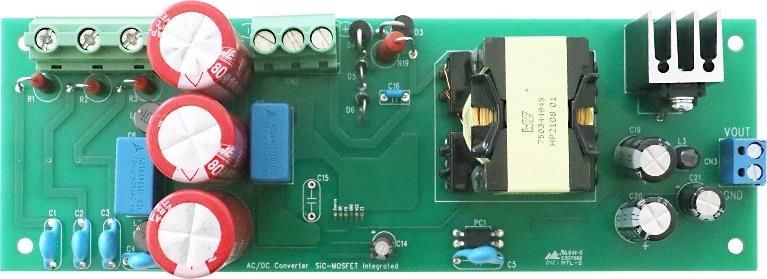
Notice

<High Voltage Safety Precautions>

  ◇ Read all safety precautions before use

     Please note that this document covers only the BM2SC123FP2-LBZ evaluation board
     (BM2SC123FP2-EVK-001) and its functions. For additional information, please refer to
     the datasheet.

  To ensure safe operation, please carefully read all precautions before
  handling the evaluation board
                    Depending on the configuration of the board and voltages used,

                    Potentially lethal voltages may be generated.
                    Therefore, please make sure to read and observe all safety precautions described in
                    the red box below.

    Before Use
  [1] Verify that the parts/components are not damaged or missing (i.e. due to the drops).
  [2] Check that there are no conductive foreign objects on the board.
  [3] Be careful when performing soldering on the module and/or evaluation board to ensure that solder
      splash does not occur.
  [4] Check that there is no condensation or water droplets on the circuit board.

    During Use
  [5] Be careful to not allow conductive objects to come into contact with the board.
  [6] Brief accidental contact or even bringing your hand close to the board may result in
       discharge and lead to severe injury or death.
  Therefore, DO NOT touch the board with your bare hands or bring them too close to the board.
  In addition, as mentioned above please exercise extreme caution when using conductive tools such as
  tweezers and screwdrivers.
  [7] If used under conditions beyond its rated voltage, it may cause defects such as short-circuit or,
       depending on the circumstances, explosion or other permanent damages.
  [8] Be sure to wear insulated gloves when handling is required during operation.

   After Use
  [9] The ROHM Evaluation Board contains the circuits which store the high voltage. Since it stores the
      charges even after the connected power circuits are cut, please discharge the electricity after using
      it, and please deal with it after confirming such electric discharge.
  [10] Protect against electric shocks by wearing insulated gloves when handling.

  This evaluation board is intended for use only in research and development facilities and
  should by handled only by qualified personnel familiar with all safety and operating
  procedures.
  We recommend carrying out operation in a safe environment that includes the use of high
  voltage signage at all entrances, safety interlocks, and protective glasses.

www.rohm.com                                                                                               HVB01E
© 2019 ROHM Co., Ltd. All rights reserved.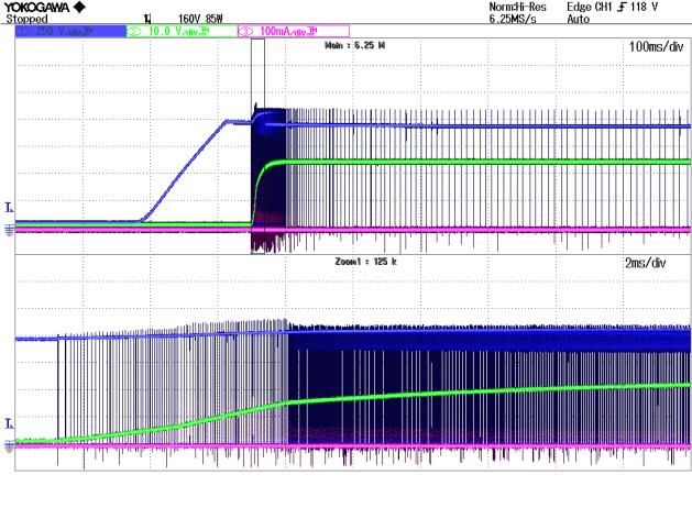
User’s Guide

AC/DC Converter

Built-in SiC MOSFET
Isolated Fly-back Converter
QR method Output 48 W 24 V
BM2SC123FP2-LBZ Reference Board
BM2SC123FP2-EVK-001

Feature
(1) Built-in 1700 V SiC MOSFET
(2) Wide input voltage range by SiC MOSFET: DC = 300 V to 900 V, AC = 210 Vac to 480 Vac
(3) High power surface mount type package TO263-7L.
(4) This is a ranked product that guarantees a long-term supply for the industrial equipment market.

                                                            Figure 1. BM2SC123FP2-EVK-001
Electrical Specification
  Input Conditions

                   Parameter                            Min                  Typ       Max    Units              Conditions

     Input Voltage Range (DC)                            300                  -        900     V
     Input Voltage Range (AC)                            210                  -        480    Vac
     Input AC Frequency                                   47               50 / 60      63    Hz
     Operating Temperature Range                         -10                +25        +65    °C

  Electrical Characteristics
   Not guarantee the characteristics, is representative value. Unless otherwise noted: VIN = 600 V (DC), Io = 1.0 A, Ta = 25 °C

                   Parameter                            Min                  Typ       Max    Units              Conditions
     Output Voltage                                     22.8                 24.0      25.2    V
     Maximum Output Power                                 -                    -        48     W      Io = 2 A
     Output Current Range (Note 1)                       0.0                   -       2.0     A
     Stand-by Power                                       -                  310         -    mW      Io = 0 A
     Efficiency                                           -                   91         -     %      Io = 2 A, VIN=300 V(DC)
     Output Ripple Voltage (Note 2)                       -                    -       200    mVpp
   (Note 1) Adjust operating time, within any parts surface temperature under 105 °C
   (Note 2) Not include spike noise

© 2021 ROHM Co., Ltd.                                                                                     No. 64UG007E Rev.003
                                                                               1/14                                  Jun. 2021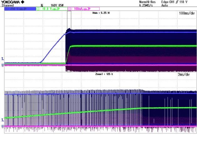
BM2SC123FP2-EVK-001                                                                                          User’s Guide

Operation Procedure
 1. Operation Equipment
  (1) 3 Phase AC Power supply 210 Vac to 480 Vac, or DC Power supply 300 Vdc to 900 Vdc. (80 W or more)
  (2) Electronic Load capacity 2.0 A
  (3) DC voltage meter

 2. Connect method
  (1) Turn off each power supply and connect the measuring instrument as shown below.
  (2) Set the power supply within the usage range and turn on the power.
  (3) If using electronic load, set it between 0 A to 2 A.
  (4) Connect the output DC voltage meter directly to the output and measure the voltage by sensing.
  (5) When removing the measuring instrument, set the input voltage to 0 V and check that the voltage of the input electrolytic
  capacitors C8, 9, 10 are 10 V or less. After that, turn off the power of each measuring instrument and remove it.
  (Note that you may get an electric shock if high voltage remains in the input capacitor.)

                     Input 210 Vac to 480 Vac                                                     Input 300 Vdc to 900 Vdc

                                                           VOUT
                                                                                       -      +
                                                                                                                             VOUT
                                                             V
                                                                                                                              V
                                                                 Io
                                                    +24V                                                                          Io
                                                                                                                      +24V

                                                    GND
                                                                                                                      GND

                                       Output Current                                                    Output Current
                                        Io = 0 to 2 A                                                     Io = 0 to 2 A

  Figure 2. Input with 3-phase AC power supply                               Figure 3. Inputting with DC power supply

© 2021 ROHM Co., Ltd.                                                                                  No. 64UG007E Rev.003
                                                                      2/14                                        Jun. 2021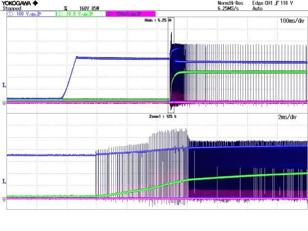
© 2021 ROHM Co., Ltd.
                                                                                                           Application Circuit
                                                                                                                                 BM2SC123FP2-EVK-001

                                                                                               RF2001T3D
                                                                                               350V/20A

                                                       1.5KE200A

                                                       1.5KE200A

                                   180uF
                                   400V

                                           2.2M

  3/14
                                           2.2M

                                   180uF
                                   400V
                                                  BM2SC12xFP2                      0.2A 400V
                                                                                 RRE02VSM4S

                                                                          10uF
                                                                   N.M.

                                                                                     100k
                                   180uF
                                           30k
                                   400V
                                                                                                                                 User’s Guide

No. 64UG007E Rev.003
           Jun. 2021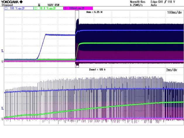
BM2SC123FP2-EVK-001 User’s Guide
BOM LIST
Item Specifications Parts name Manufacture
SCREW - SEMS-SCREW-P4-3X8 TOMOHO
CL C1,C2,C3,C4,C5 2200 pF, 300 V DE1E3RA222MJ4BP01F MURATA
CFL C6,C7 33 nF, 1600 V B32672L1333J TDK
CAL C8,C9,C10 180 µF, 400 V 860021381024 WURTH ELECTRONIK
CAP C11,C24 1000 pF, 100 V HMK107B7102KA-T TAIYO YUDEN
CAP C12 47 pF, 250 V GRM1885C2E470JW07 MURATA
CAP C13 10 µF, 50 V GRM31CD71H106KE11 MURATA
CAL C14 22 µF, 50 V UHD1H220MDD NICHICON
OTHER C15 - NON MOUNTED -
CL C16 2200 pF, 1000 V RDER73A222K2K1H03B MURATA
CAP C18 680 pF, 1000 V GRM31B5C2J681FW01L MURATA
CAL C19,C20 470 µF, 35 V EKZE350ELL471MJ20S UNITED CHEMI-CON
CAL C21 220 µF, 35 V UHD1V221MPD NICHICON
CAP C22 10 µF, 50 V GRM31CD71H106KE11 MURATA
CAP C23 0.1 µF, 100 V HMK107B7104MA-T TAIYO YUDEN
CN CN1 - 691250910003 WURTH ELECTRONIK
CN CN2 - 691250610003 WURTH ELECTRONIK
CN CN3 - 691101710002 WURTH ELECTRONIK
DI D1,D2,D10,D11,D12,D13,D14 1 A, 1200 V D1FK120 SHINDENGEN
ZD D3,D4 Zener Diode, 200 V 1.5KE200A LITTELFUSE
FRD D5,D6 FRD, 1 A, 1000 V UF4007 ON SEMICONDUCTOR
DI D7 0.1 A, 80 V 1SS355VM ROHM
DI D8 0.2 A, 400 V RRE02VSM4S ROHM
FRD D9 FRD, 20 A, 300 V RF2001T3DNZ ROHM
HS HS2 22.9 k/W IC-1625-STL SANKYO THRMOTECH
IC IC1 - BM2SC123FP2-LBZ ROHM
IC IC2 TL431BIDBZT TI
L L1,L2 1000 µH 768772102 WURTH ELECTRONIK
L L3 2.2 µH 7447462022 WURTH ELECTRONIK
PC PC1 - LTV-817M-B LITEON
RES R1,R2,R3 10 Ω PR02FS0201009KR500 VISHAY
RES R4,R5,R6,R7,R8,R9 470 kΩ MCR18EZPJ474 ROHM
RES R10,R11 1 MΩ KTR18EZPJ105 ROHM
RES R12,R13 470 kΩ KTR18EZPJ474 ROHM
RES R14 0.47 Ω LTR100JZPFLR470 ROHM
RES R15 100 kΩ KTR03EZFX1003 ROHM
RES R16,R20 10 Ω MCR25JZHJ100 ROHM
RES R17 12 kΩ MCR03EZPFX1202 ROHM
RES R18 10 Ω MCR18EZPJ100 ROHM
RES R19 220 kΩ PR03000202203JAC00 VISHAY
RES R21 82 kΩ MCR03EZPFX8202 ROHM
RES R22 4.7 kΩ MCR03EZPFX4701 ROHM
RES R23,R26 10 kΩ MCR03EZPFX1002 ROHM
RES R24 2.2 kΩ MCR03EZPFX2201 ROHM
RES R25 1 kΩ MCR03EZPFX1001 ROHM
RES R27 30 kΩ MCR03EZPJ303 ROHM
RES R28,R29 470 kΩ KTR18EZPJ225 ROHM
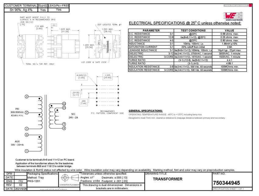
T T1 PQ3230 750344945 WURTH ELECTRONIK
© 2021 ROHM Co., Ltd. No. 64UG007E Rev.003
4/14 Jun. 2021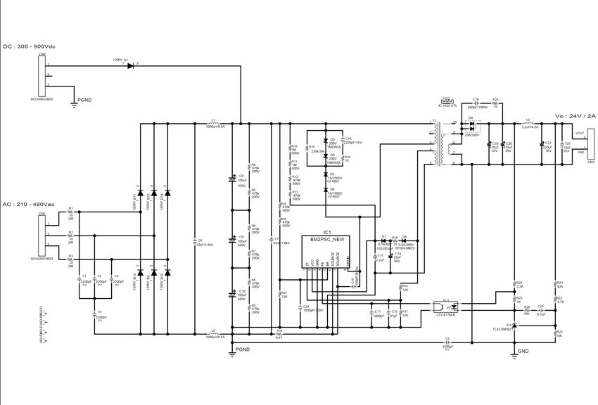
BM2SC123FP2-EVK-001                                                                                                 User’s Guide

BM2SC12xFP2 Overview

 Feature
   ◼ Long Time Support Product for Industrial Applications                Key specifications
   ◼ TO263-7L Package                                                     ◼    Operating Power Supply Voltage Range:
   ◼ Built-in 1700 V/9.2 A/1.15 Ω SiC-MOSFET                                        VCC:                             15.0 V to 27.5 V
   ◼ Quasi-resonant Type                                                            DRAIN:                               1700 V (Max)
   ◼ Frequency Reduction Function                                         ◼    Normal Operating Current:                  800 µA (Typ)
   ◼ Low Current Consumption (19 µA) during Standby                       ◼    Burst Operating Current:                   500 µA (Typ)
   ◼ Burst Operation at Light Load                                        ◼    Maximum Operating Frequency:              120 kHz (Typ)
   ◼ SOURCE Pin Leading Edge Blanking                                     ◼    Operating Temperature:               -40 °C to +105 °C
   ◼ VCC UVLO (Under Voltage Lockout protection)
   ◼ VCC OVP (Over Voltage Protection)
   ◼ Over Current Protection Circuit per Cycle                                                 Table 1. Series Line-up
   ◼ Soft Start Function                                                     Product name               FB OLP             VCC OVP
                                                                          BM2SCQ121FP2-LBZ           Auto Restart        Latch
   ◼ ZT Pin Trigger Mask Function                                         BM2SCQ122FP2-LBZ           Latch               Latch
   ◼ ZT OVP (Over Voltage Protection)                                     BM2SCQ123FP2-LBZ           Auto Restart        Auto Restart
                                                                          BM2SCQ124FP2-LBZ           Latch               Auto Restart
   ◼ BR UVLO (Under Voltage Lockout Protection)

                                                                          Application
                                                                          Power supply for Industrial Equipment, AC Adaptor, Household
                                     DRAIN                                Application
                    EXP-PAD

                                                                          Package                     W (Typ) x D (Typ) x H (Max)
                                                                                  TO263-7L                10.18 mm x 15.5 mm x 4.56 mm

               ZT      VCC    GND      FB     BR   SOURCE SOURCE

                1       2      3       4      5      6        7

                     Figure 4. Pin Configuration

                                                   Table 2. BM2SC123FP2 PIN description

                                      No.            Name                        Function

                                       1                 ZT        Zero current detection pin
                                       2              VCC          Power supply input pin
                                       3              GND          GND pin
                                       4                 FB        Feedback signal input pin
                                       5                 BR        AC voltage detect pin
                                       6            SOURCE         MOSFET SOURCE pin
                                       7            SOURCE         MOSFET SOURCE pin
                                    EXP-PAD         DRAIN          MOSFET DRAIN pin

© 2021 ROHM Co., Ltd.                                                                                        No. 64UG007E Rev.003
                                                                     5/14                                               Jun. 2021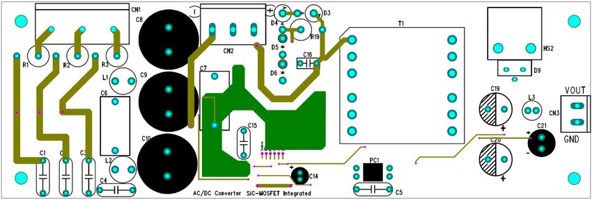
BM2SC123FP2-EVK-001                                                                               User’s Guide

Transformer Specification
Transformer design example

                                                Figure 5. Transformer Specification

                                           Table 3. Core and Bobbin Information

                                    Item                              Material

                                    Core                                TP4A
                                   Bobbin                          PQ3230 WH9100

                                              Table 4. Winding Specification

                                     Pin                  Turn No.             Wire diagram
                                   3=>1 pin                  88T                    AWG25
                             11=>9 pin, 12=>8 pin            20T                  4 x AWG24
                                 4 pin=>5 pin                18T                    AWG32

© 2021 ROHM Co., Ltd.                                                                         No. 64UG007E Rev.003
                                                          6/14                                           Jun. 2021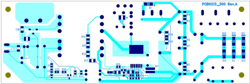
BM2SC123FP2-EVK-001                                                                                                                                                       User’s Guide

Performance Data

                                                                                                                                                             Io-Efficiency
                                                  Vo - Io                300Vdc                               100.0%
                             24.5
                                                                         900Vdc
     Output Voltage Vo (V)

                                                                                                               90.0%
                             24.3

                                                                                           Efficiency η (%)
                                                                                                               80.0%
                             24.1                                                                              70.0%
                             23.9                                                                              60.0%                                                           VIN=300 Vdc
                             23.7                                                                              50.0%                                                           VIN=900 Vdc

                             23.5                                                                              40.0%
                                     0    0.5     1    1.5    2    2.5     3       3.5                                                    0           0.5            1              1.5         2
                                                 Outout Current Io (A)                                                                                      Output Current Io (A)
                             Figure 6. Output Voltage vs Output Current –                                      Figure 7. Output Current vs Efficiency

                                                Vo - Vin                                                                                                      Vin - Fsw
                                                                         IOUT=0                                                      60
                             24.5
                                                                         IOUT=2A
     Output Voltage Vo (V)

                                                                                                               Frequency Fsw [kHz)

                                                                                                                                     50

                              24
                                                                                                                                     40

                             23.5                                                                                                    30
                                    300   400      500     600   700    800       900                                                     300   400         500     600      700          800   900
                                                Input Voltage Vin (Vdc)                                                                                 Input Voltage Vin (Vdc)
                             Figure 8. Input Voltage vs Output Voltage                     Figure 9. Input Voltage Vin vs Frequency (Io = 2 A)

© 2021 ROHM Co., Ltd.                                                                                                                                              No. 64UG007E Rev.003
                                                                                    7/14                                                                                      Jun. 2021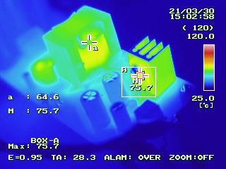
BM2SC123FP2-EVK-001                                                                          User’s Guide

Performance Data – Continued

      V_Drain 100 V/div           I_FET 1 A/div                V_Drain 250 V/div        I_FET 1 A/div

          Figure 10. Vin_dc = 300 V, Io = 0.5 A                  Figure 11. Vin_dc = 900 V, Io = 0.5 A
                         Primary Side                                        Primary Side

      Secondary diode Vak 50 V/div       I_Diode 2 A/div      Secondary diode Vak 50 V/div     I_Diode 2 A/div

          Figure 12. Vin_dc = 300 V, Io = 0.5 A                  Figure 13. Vin_dc = 900 V, Io = 0.5 A
                        Secondary Side                                      Secondary Side

© 2021 ROHM Co., Ltd.                                                                   No. 64UG007E Rev.003
                                                       8/14                                        Jun. 2021
BM2SC123FP2-EVK-001 User’s Guide
Performance Data – Continued
V_Drain 100 V/div I_FET 1 A/div V_Drain 250 V/div I_FET 1 A/div
Figure 14. Vin_dc = 300 V, Io = 2.0 A Figure 15. Vin_dc = 900 V, Io = 2.0 A
Primary Side Primary Side
Secondary diode Vak 50 V/div I_Diode 2 A/div Secondary diode Vak 50 V/div I_Diode 2 A/div
Figure 16. Vin_dc = 300 V, Io = 2.0 A Figure 17. Vin_dc = 900 V, Io = 2.0 A
Secondary Side Secondary Side
© 2021 ROHM Co., Ltd. No. 64UG007E Rev.003
9/14 Jun. 2021BM2SC123FP2-EVK-001 User’s Guide
Performance Data – Continued
V_Drain 100 V/div I_FET 1 A/div V_Drain 250 V/div I_FET 1 A/div
ZOOM ZOOM
Figure 18. Output short Vin_dc = 300 V Figure 19. Output short Vin_dc = 900 V
Primary side Primary side
V_Anode 50 V/div I_Diode 5 A/div V_Anode 50 V/div I_Diode 5 A/div
ZOOM ZOOM
Figure 20. Output short Vin_dc = 300 V Figure 21. Output short Vin_dc = 900 V
Secondary side Secondary side
© 2021 ROHM Co., Ltd. No. 64UG007E Rev.003
10/14 Jun. 2021BM2SC123FP2-EVK-001 User’s Guide
Performance Data – Continued
V_Drain 100 V / div Vo 10 V / dvi I_FET 1 A/div V_Drain 250 V / div Vo 10 V / dvi I_FET 1 A/div
ZOOM ZOOM
Figure 22. Startup Vin_dc = 300 V, Io = 0 A Figure 23. Startup Vin_dc = 900 V, Io = 0 A
V_Drain 100 V / div Vo 10 V / dvi I_FET 1 A/div V_Drain 250 V / div Vo 10 V / dvi I_FET 1 A/div
ZOOM ZOOM
Figure 24. Startup Vin_dc =300 V, Io = 2 A Figure 25. Startup Vin_dc = 900 V, Io = 2 A
© 2021 ROHM Co., Ltd. No. 64UG007E Rev.003
11/14 Jun. 2021BM2SC123FP2-EVK-001 User’s Guide
Performance Data – Continued
Vo 500 mV/div(AC) Io 2 A/div Vo 500 mV/div(AC) Io 2 A/div
Figure 26. Load Response Vin_dc = 300 V, Io = 02 A Figure 27. Load Response Vin_dc = 900 V, Io = 02 A
Vo 50 mV/div(AC) I_Diode 5 A/div Vo 50 mV/div(AC) I_Diode 5 A/div
Figure 28. Output Ripple Voltage Vin_dc = 300 V, Figure 29. Output Ripple Voltage Vin_dc = 900 V,
Io = 2 A Io = 2 A
© 2021 ROHM Co., Ltd. No. 64UG007E Rev.003
12/14 Jun. 2021BM2SC123FP2-EVK-001 User’s Guide
Performance Data – Continued
IC 75.0℃ Transformer 77.0℃ Diode 75.7℃
Figure 30. Parts surface temperature (Vin_dc = 900V, Iout = 2A after 30min.)
)
Consider selecting parts by checking the temperature range of the parts to be used.
PCB
Size : 60 mm x 180 mm
Figure 31. Top Layout (Top view)
Figure 32. Bottom Layout (Bottom view)
© 2021 ROHM Co., Ltd. No. 64UG007E Rev.003
13/14 Jun. 2021BM2SC123FP2-EVK-001 User’s Guide
Revision History
Date Rev. Changes
28.Apr.2021 001 New Release
・P4 Transformer specification is modified
1.Jun.2021 002
・P6 Transformer specification modified
24.Jun.2021 003 ・P4 Transformer name change
© 2021 ROHM Co., Ltd. No. 64UG007E Rev.003
14/14 Jun. 2021Notice
Notes
1) The information contained herein is subject to change without notice.
2) Before you use our Products, please contact our sales representative and verify the latest specifica-
tions :
3) Although ROHM is continuously working to improve product reliability and quality, semicon-
ductors can break down and malfunction due to various factors.
Therefore, in order to prevent personal injury or fire arising from failure, please take safety
measures such as complying with the derating characteristics, implementing redundant and
fire prevention designs, and utilizing backups and fail-safe procedures. ROHM shall have no
responsibility for any damages arising out of the use of our Poducts beyond the rating specified by
ROHM.
4) Examples of application circuits, circuit constants and any other information contained herein are
provided only to illustrate the standard usage and operations of the Products. The peripheral
conditions must be taken into account when designing circuits for mass production.
5) The technical information specified herein is intended only to show the typical functions of and
examples of application circuits for the Products. ROHM does not grant you, explicitly or implicitly,
any license to use or exercise intellectual property or other rights held by ROHM or any other
parties. ROHM shall have no responsibility whatsoever for any dispute arising out of the use of
such technical information.
6) The Products specified in this document are not designed to be radiation tolerant.
7) For use of our Products in applications requiring a high degree of reliability (as exemplified
below), please contact and consult with a ROHM representative : transportation equipment (i.e.
cars, ships, trains), primary communication equipment, traffic lights, fire/crime prevention, safety
equipment, medical systems, servers, solar cells, and power transmission systems.
8) Do not use our Products in applications requiring extremely high reliability, such as aerospace
equipment, nuclear power control systems, and submarine repeaters.
9) ROHM shall have no responsibility for any damages or injury arising from non-compliance with
the recommended usage conditions and specifications contained herein.
10) ROHM has used reasonable care to ensurH the accuracy of the information contained in this
document. However, ROHM does not warrants that such information is error-free, and ROHM
shall have no responsibility for any damages arising from any inaccuracy or misprint of such
information.
11) Please use the Products in accordance with any applicable environmental laws and regulations,
such as the RoHS Directive. For more details, including RoHS compatibility, please contact a
ROHM sales office. ROHM shall have no responsibility for any damages or losses resulting
non-compliance with any applicable laws or regulations.
12) When providing our Products and technologies contained in this document to other countries,
you must abide by the procedures and provisions stipulated in all applicable export laws and
regulations, including without limitation the US Export Administration Regulations and the Foreign
Exchange and Foreign Trade Act.
13) This document, in part or in whole, may not be reprinted or reproduced without prior consent of
ROHM.
Thank you for your accessing to ROHM product informations.
More detail product informations and catalogs are available, please contact us.
ROHM Customer Support System
http://www.rohm.com/contact/
ZZZURKPFRP
652+0&R/WG$OOULJKWVUHVHUYHG
5%You can also read