4 & 6 Bike Rack Owners Manual - Version 1.0 - Mammoth Mounts
←
→
Page content transcription
If your browser does not render page correctly, please read the page content below
4 & 6 Bike Rack
Owners Manual

      Version 1.0
Parts Diagram
Upper Mast (x1) Lower Mast (x1)
Pivot (x2)
Side Plates (x2)
Hitch with Wedge (x1)
Bar Holder (x4 or x6)
Upper Horizontal Bar (x1) Lower Horizontal Bar (x1)
5/8” Pin (x1) 1/2” Pin (x2) HDPE 1/2” Washer (x4)
3/8” Carriage Bolt (x8 or x12) 1/2” x 3 1/2” Bolt (x7) 1/2” x 3 3/4” Bolt (x3)
1/2” Nylock Nut (x10)
3/8” Steel Washer (x8 or x12) 1/2” Steel Washer Gold (x20)
3/8” Nylock Nut (x8 or x12)
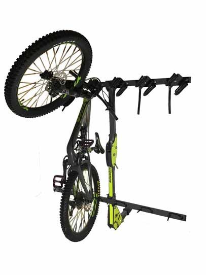
1/2” Steel Washer Silver(x8)Congratulations on the purchase of your Mammoth Mounts 4 or 6 vertical bike rack. The Mammoth Mounts
series of bike racks were designed primarily around transporting single crown mountain bikes however the
racks will work with a variety of bikes including bmx bikes, gravel bikes, kids bikes and road bikes. This
owners manual is intended to guide you through the safe setup and use of your rack. Please read instruc-
tions carefully.
Rack Assembly
Tools required: Figure 1
-3/4” wrench or socket
-9/16” wrench or socket
Step 1
We recommend building the rack from the bottom
up. Start by placing the zinc plated hitch piece into
the receiver of the vehicle. Orientate the hitch piece Gold Steel
Washers
so that the hitch wedge is in the top left hand corner
of the hitch receiver. Use the supplied 5/8” hitch pin
to secure the zinc plated hitch into the receiver on
the vehicle. Using a 9/16” wrench or socket tighten
the bolt head on the front of the hitch piece so that
Silver Steel
the hitch no longer wobbles in the receiver. Washers
Step 2
Install the side plates and lower mast as shown in Figure 2
figure 1 using 1/2” x 3 3/4” bolts, nylock nuts, wash-
ers and a 1/2” pin. The decal on the lower mast
should be facing away from the vehicle. Use gold Silver Steel
Washers
steel washers on the outside of the side plates and
use silver steel washers between the sideplates and
the lower mast/hitch. The pivot bolt should be tight- Gold Steel
Washers
ened so that the lower mast can rotate within the
side plates with some force (approx 20ft/lbs). Use
caution not to overtighten.
Step 3
Install the pivot plates and upper mast as shown in
figure 2 using 1/2” x 3 1/2” bolts, nylock nuts, wash-
ers and a 1/2” pin. Position the upper mast so that
the decal is facing towards the vehicle. The pivot bolt
should be tightened so that the upper mast can
rotate within the pivot plates with gentle force
(approx 20ft/lbs). Use caution not to overtighten.Step 4
Install the upper and lower horizontal bars as shown Figure 3
in figure 3 using 1/2” x 3 1/2” bolts, nylock nuts and
washers. The upper horizontal bar should be posi-
tioned so that the hole spaced closest to the outside
edge is on the right hand side of the rack and the
angled face of the bracket is facing downwards. The
lower horizontal bar should be positioned so that the
wheel brackets are on top of the bar.
Step 5
Install the handle bar brackets using the provided
3/8” carriage bolts, washers and nylock nuts as
shown in figure 4.
Step 6
Once all of the bar brackets are installed check all of
the bolts on the entire rack to ensure everything is
tight.
Figure 4
Step 7
You are now ready to rack and roll! Enjoy your new
Mammoth rack.
Replacment parts can be purchased at
www.mammothmounts.comLoading and Use Vehicle Mounting Use only on a vehicle equipped with a 2” class III or class IV hitch receiver with a minimum tongue weight capacity of 250lbs. To lower the center of gravity we recommend mounting the rack in the folded or collapsed position. If clearance allows always mount the bike rack in the deepest of the two 5/8” hitch pin locations which will bring the rack closer to the rear of the vehicle. Install 5/8“ hitch pin or 5/8” hitch pin lock to secure the rack to the hitch receiver on the vehicle. Tighten the hitch wedge using a 9/16” wrench or ratchet until the rack no longer wobbles in the hitch receiver. To remove the rack simply loosen the 9/16” bolt on the front of the hitch followed by removal of the 5/8” hitch pin. If the wedge fails to retract gently push on the 9/16” bolt head or lightly tap the bolt head with a mallet until it is free. Once the hitch pin is removed and the wedge is free/loose the rack can be removed from the vehicle. Bike Mounting Always load the rack from left to right and unload the rack from right to left. To mount the bikes simply grab each bike by the front fork and the rear seat stay. Place the handlebars in the handlebar bracket so that the stem is positioned between the two forks on the bracket. Take caution when loading any bike with handlebar or stem mounted accessories as the brackets may damage these acceso- ries. Use the rubber strap on the handlebar bracket to go over the handle bar and down to the mounting post. The rubber strap should not go over the stem of the bike. Align the rear wheel to the center of the corresponding rear wheel holder. Secure the rear wheel in place using the bungee. A conventional mountain bike will use the ball as a means of securing the bungee in the rear wheel holder, a fat bike will use the loop of the bungee as a means of securing the rear wheel in the wheel holder as it requires extra length. The rear wheel bungee can be adjusted by tying the knot in a separate location. Stagger the pedals of each bike to ensure that they do not make contact with the adjacent bike(s). To remove the bikes simply follow these steps in reverse while unloading from right to left. Note: If using road bikes we recommend removing the adjacent handlebar bracket to prevent the drop bars from touching the adjacent bracket. In this scenario a four bike rack would carry two road bikes and a six bike rack would carry three road bikes. On a four bike rack you would be required to remove only the second handlebar bracket (bikes would mount in the # 1 and 4 position on the rack). On a six bike rack you would be required to remove the second and fifth handlebar brackets (bikes would mount in the #1, 4 and 6 position on the rack). Pivoting the Rack It is very important that all bikes are removed from the rack before attempting to pivot or adjust the rack. Failure to do so could result in serious injury. When pivoting the rack to access the rear of the vehicle simply remove the 1/2” pin from the side plates while firmly supporting the mast of the rack. Place the pin in the rearward most hole on the side plates and gently let the mast downward until it rests against the pin (the pin does not go through the mast at this location). This position is for accessing the rear of the vehicle only and cannot be used while the vehicle is in motion.
Folding the Rack
It is very important that all bikes are removed from the rack before attempting to fold the rack at the center pivot. Simply remove the
1/2” pin from the center pivot while supporting the upper mast. Once the pin is removed gently lower the upper mast and place the
pin through the pivot plates and through the lower mast at the second pin hole location on the pivot plates. The rack can be trans-
ported in this position without any cargo attached.

Maintenance
To ensure the longevity and safe use of your Mammoth rack it is important that the rack is regularly maintained. Check all bolts includ-
ing the hitch wedge bolt before each use. Monitor pivot points for wear, if HDPE washers are beginning to show signs of wear replace
with new HDPE washers. The hitch wedge comes prelubricated with anti sieze compound on the threads, if the wedge bolt becomes
difficult to turn relubricate with anti sieze compound. We recommend removing the rack from the receiver every two weeks to clean
the receiver to ensure that the rack does not seize in the receiver.

Remove road debris off nuts and bolts to prevent corrosion.

Routinely monitor the condition of the handle bar brackets and wheel holders and if the rubber or bungee begins to show signs of
wear or deterioration replace with new pieces. Each Mammoth rack comes coated with a durable powder coat coating. In the unlikely
event that the paint is chipped it is important that all chips are touched up with paint to ensure that the rack does not begin to rust.

Important Warnings
Inadequately secured bikes and racks that are mounted or used incorrectly can come loose during travel and cause serious accidents. It
is the owners responsibility to ensure that installation, handling and use are carried out in accordance with this manual and the vehicles
owners manual. These instructions should be kept together with the vehicles operating instructions and carried in the vehicle when in
use and en route.

Check attachement hardware and load for tight fit and function:
-Before the start of any journey
-After driving a short distance following a rack or load install
-At regular intervals on long journeys
-More frequently on rough terrain
-After interruption of a journey during which the vehicle was left unsupervised (check for damage due to outside intervention)

Do not exceed the maximum load for your rack (220lbs), the maximum load specified by the vehicle manufacturer or the maximum
tongue weight specified by the hitch manufacturer. Load shall be uniformily distributed while maintaining the load as close to the
center of the rack as possible. Bikes should not be loaded in any way that causes them to extend past the vehicle and increase the
overall vehicle width beyond local transportation regulations.

Do not use any 3rd party hitch adapters or hitch extensions to mount the rack to the vehicle.
Do not use rack Off-Road*. (*Rough, washed out, boulder-and-rut-strewn backroads)
- Smooth gravel roads are not considered off-road
Do not take the rack through automatic carwash.
Do not use rear bicycle fenders with this product.

Be aware that the vehicle’s driving characteristics and braking behaviour (including in curves) might change and that the vehicle might
become vulnerable to side winds when the rack is fitted.
Depending on the carrier model, the car’s tail lights can be obstructed. If that is the case, an external light board must be fitted.
An additional number plate might be required. This should be attached to the appropriate part of the carrier in accordance with local
laws.
The vehicle’s speed must always be adjusted to the load being carried and the current driving conditions, such as the road type, road
quality, wind conditions, traffic intensity and applicable speed limits, but must under no circumstances exceed 130 km/h. Applicable
speed limits and other traffic regulations must always be observed.
Drive slowly over speed bumps, maximum speed 10 km/h.
Be aware that wind noise may be generated during transport and may vary depending on the vehicle and load.
For reasons of fuel economy and environmental impact as well as the safety of other road users, the rack must be removed from the
vehicle when not in use.

If the vehicle is equipped with an automatic boot or tailgate opening function, this function must be disabled and the luggage compart-
ment must be opened manually when the rack is fitted, to avoid damage to the vehicle and/or the rack.

Warranty
LIMIT OF LIABILITY
THIS WARRANTY ONLY COVERS REPAIR, REPLACEMENT OR REFUND FOR THE COVERED MAMMOTH BICYCLE PRODUCTS INC FOUR OR
SIX BIKE VERTICAL BIKE RACKS. ANY DAMAGE TO VEHICLE OR PROPERTY IS NOT COVERED BY THIS WARRANTY. PERSONAL INJURY IS
NOT COVERED BY THIS WARRANTY.

Mammoth Bicycle Products Inc honors the structural warranty on all Mammoth Bicycle Products brand products for original owners of
the product for a period of 24 months from original date of purchase. Warranty is not transferable.

If a Mammoth rack that is covered by the terms of this warranty and is determined by Mammoth Bicycle Products Inc, to be defective,
Mammoth Bicycle Products Inc will repair or replace the defective parts. Mammoth Bicycle Products Inc may choose in some cases to
offer the owner a refund of up to the original purchase price of the product in lieu of repairing or replacing the product.

The warranty does not cover any conditions that are beyond Mammoth Bicycle Products Inc control. This includes, but is not limited to,
the following: excessive loading, improper assembly, improper installation, theft, or any use that is not consistent with the user guide
that is included with the product.

The Mammoth warranty does not cover normal wear and tear, scratches, cosmetic oxidation, accidents, or damage
due to unauthorized repairs or modifications. Wear parts include: EPDM handlebar bungees, wheel holder bungees, HDPE pivot
washers, rubber handlebar bracket protectors, decals.

If you are the original owner of a defective Mammoth product, please contact Mammoth Bicycle Products Inc at
info@mammothmounts.com. A representative will work to quickly resolve the problem. If repairs are necessary, the owner will be
responsible for the cost of returning the product to Mammoth for repair. No product should be returned to Mammoth without prior
authorization from Mammoth staff.
You can also read