Operation Manual Mower Tractor Scarifier 100 cm - WilTec ...
←
→
Page content transcription
If your browser does not render page correctly, please read the page content below

Operation Manual

                     Mower Tractor Scarifier 100 cm
                                                   51705

                              Illustration similar, may vary depending on model

Read and follow the operating instructions and safety information before using for the first time.

Technical changes reserved!
Due to further developments, illustrations, functioning steps and technical data can differ insignific -
antly.

Updating the documentation
If you have suggestions for improvement or have found any irregularities, please contact us.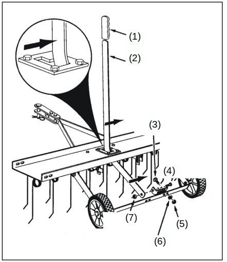
The information contained in this document may alter at any time without previous notice. It is prohib-
ited to copy or spread any parts of this document in any way without prior written allowance. All rights
reserved.
The WilTec Wildanger Technik GmbH cannot be held accountable for any possible mistakes in this
operating manual, nor in the diagrams and figures shown.
Even though, the WilTec Wildanger Technik GmbH has undergone biggest possible efforts to ensure
that the operating manual is complete, faultless and up to date, mistakes cannot be entirely avoided.
If you should find a mistake or wish to make a suggestion for improvement, we look forward to hearing
from you.

Send an e-mail to:

service@wiltec.info

or use our contact form:

https://www.wiltec.de/contacts/

The most recent version of this manual in various languages can be found in our online shop via:

https://www.wiltec.de/docsearch

Our postal address is:

WilTec Wildanger Technik GmbH
Königsbenden 12
52249 Eschweiler
Germany

Do you wish to pick goods up? Our pick-up address is:

WilTec Wildanger Technik GmbH
Königsbenden 28
52249 Eschweiler
Germany

To shorten the waiting time and allow for a rapid on-site transaction, we ask you to call us previously
or placing your order via the webshop.

E-mail: service@wiltec.info
Tel:+49 2403 55592-0
Fax: +49 2403 55592-15

To return orders for exchange, repair or for other purposes, please use the following address. Atten -
tion! To allow for a smooth execution of your complaint or return, it is important to contact our cus -
tomer service team before returning the goods.

Returns Department
WilTec Wildanger Technik GmbH
Königsbenden 28
52249 Eschweiler

E-mail: service@wiltec.info
Tel:+49 2403 55592-0
Fax: +49 2403 55592-15

© by WilTec Wildanger Technik GmbH             Item 51705                                        Page 2
http://www.WilTec.de
http://www.aoyue.eu                                                                            01 2021-1
http://www.teichtip.de

Introduction
Thank you for purchasing this quality product. To minimize the risk of injury we urge that our cli-
ents take some basic safety precautions when using this device. Please read the operation in-
structions carefully and make sure you have understood its content.
Keep these operation instructions safe.
General safety instructions
READ and UNDERSTAND this manual completely before using the 40” scarifier.
The operator must read and understand all safety, warning and operating, maintenance and
storage instructions before operating this equipment.
Failure to properly operate and maintain the scarifier could result in serious injury to the oper -
ator or bystanders.
Operation warnings
Do at no time carry passengers, sit or stand on the scarifier.
Do not allow children to play on, stand upon or climb on the scarifier.
Always inspect the equipment before using to assure it is in good working condition.
Replace or repair damaged or worn parts immediately.
Always check and tighten hardware and assembled parts before operation.
Do not exceed equipment maximum tray load capacity of 70 lb.
Avoid large holes and ditches when operating the equipment.
Be careful when operating the scarifier on steep grades (hill).
ALWAYS operate at reduce speed in rough terrain, along creeks, ditches and on hillsides.
Do not operate close to creeks, ditches and public highways.
To avoid personal injury and/or equipment damage DO NOT EXCEED 5 MPH.
Always use caution when loading and unloading extra weight on the tray.
Only tow with recommended vehicles (lawn/garden tractors and ATVs).
Always refer to the vehicle owner’s manual for proper towing.
The scarifier is not designed to be used with zero-turn mowers.
Always secure and lock the scarifier thatcher to the vehicle hitch before operating.
Crush and cut hazards
Always keep your hands and feet away from moving parts while operating the equipment.
Always wear safety gear, eye protection, gloves and work boots when operating the equip-
ment.
WARNING: The warnings, cautions, and instructions outlined in this instruction manual cannot cover
all possible conditions or situations that may occur. It must be understood by the operator that com-
mon sense and caution are factors which cannot be built into this product and must be supplied by the
operator.
Assembly is required
This product requires assembly before use. See “Assembly” section for instructions. Because of the
weight and/or size of the 40” scarifier, it is recommended that another adult be present to assist with
the assembly. INSPECT ALL COMPONENTS closely upon receipt to make sure no components are
missing or damaged.
© by WilTec Wildanger Technik GmbH Item 51705 Page 3
http://www.WilTec.de
http://www.aoyue.eu 01 2021-1
http://www.teichtip.de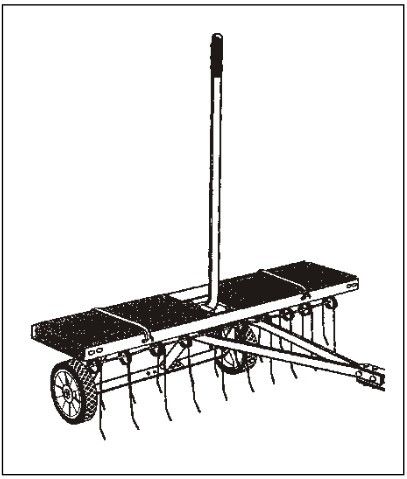
About your 40” scarifier

This 40” scarifier has a roughed steel construction and is designed to remove dead grass, matted
thatch, debris and large clippings. The 40” scarifier features a fully enclosed weight tray to increase
the penetration depth. Never exceed the rated loaded capacity of the tray of 70 lbs when operating the
scarifier.

Technical specifications on the 40” scarifier are provided in the “Specifications” section of this manual.

Controls and features identification

      Read this owner’s manual before operating the equipment. Familiarize yourself with
                    the location and function of the controls and features.
                            Save this manual for future reference.

№     Name                    Comment
1     Scarifier tray          Do not exceed maximum load capacity 70 lbs.
2     Lift handle             Positions tines up or down.
3     Tines                   Removes debris from the ground.
4     Hitch                   Pin-type design use only with approve vehicles.
5     Tyres/wheels            All-terrain for easy manoeuvring.

      CAUTION
      Read and follow all instructions for assembly and operation. Failure to properly assemble this
equipment could result in serious injury to the user or bystanders, or cause equipment damage.

© by WilTec Wildanger Technik GmbH              Item 51705                                          Page 4
http://www.WilTec.de
http://www.aoyue.eu                                                                               01 2021-1
http://www.teichtip.de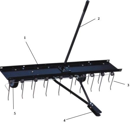
Scarifier components and assembly

Take all parts out of the shipping crate and inspect components to ensure there are no missing pieces
before starting to assemble the scarifier, follow the steps below.

Component and hardware parts

  №    Name                                  Qty.       №    Name                               Qty.
  1    Tine shield                               1      6    Lift plate                          1
  2    Spring tines                           10        7    Hitch bracket                       2
  3    Lift handle                               1      8    Hitch mount arms                    2
  4    Axle bracket                              1      9    Spring alignment wires              2
  5    Wheels                                    2

  №    Name                          Qty.   № Name                                             Qty.
  A    Shoulder bolt                   2     H       Hexagonal nut M8                            14
  B    Hexagonale bolt M8×50           2     I       Hexagonal lock nut M8                       19
  C    Hexagonal bolt M8×30            2     J       Hexagonal lock nut M10                      2
  D    Hexagonal bolt M8×20           15     K       Lock washer Ø8                              14
  E    Carriage bolt M8×25            14     L       Big flat washer Ø8                          10
  F    Hitch pin Ø10                   1     M Angle bracket                                     4
  G    Hair cotter pin Ø3              1     N       Hitch arm Mounting bracket                  3

© by WilTec Wildanger Technik GmbH            Item 51705                                       Page 5
http://www.WilTec.de
http://www.aoyue.eu                                                                          01 2021-1
http://www.teichtip.de
Assembly instructions
Tools required for assembly (1 of each):
13 mm wrench
14 mm wrench
Adjustable wrench
Pliers
Before assembling the scarifier, lay out all of the parts and hardware as shown on the previous pages.
The 40” scarifier is show in the following drawings. The assembly of the 40” and 48” is the same ex-
cept as noted in the instructions.
1. Assemble the lift plate (1) to the top of the tine
shield using four M8×20 hex bolts (2) and M8 hex
lock nuts (3) as shown in figure. Tighten.
2. Turn the tine shield upside down.
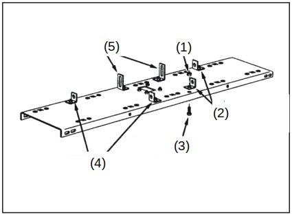
3. Assemble two (tall) hitch arm mount brackets
(5) and two (short) angle brackets (4) to the bot-
tom of the tine shield. Fasten the brackets to the
four round holes at the rear of the tine shield us-
ing four M8×20 hex bolts (3) and M8 hex lock
nuts (1). Do not tighten yet.
4. Assemble two angle brackets (4) to the round
holes in the bottom of the tine shield at the front.
Use two M8×20 hex bolts (3) and M8 hex lock
nuts (1). Do not tighten yet.
5. Fasten the hitch mount arms (2) to the outside
of the angle brackets at the front of the tine
shield. Use two M8×20 hex bolts (3) and M8 hex
lock nuts (4). Tighten and then loosen the nuts
slightly.
6. Fasten the hitch mount arms to the outside of
the hitch arm mount brackets (2) at the rear of the
tine shield. Use two M8×25 carriage bolts (1), Ø8
lock washers (6) and M8 hex nuts (5). Do not
tighten yet.
© by WilTec Wildanger Technik GmbH Item 51705 Page 6
http://www.WilTec.de
http://www.aoyue.eu 01 2021-1
http://www.teichtip.de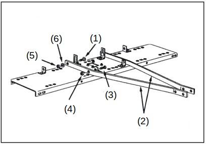
7. Assemble the front ends of the hitch mount
arms together using two M8×30 hex bolts (6) and
M8 hex lock nuts (1). Do not tighten yet.
8. Assemble the hitch brackets (3) to the top and
bottom of the hitch mount arms using two M8×50
hex bolts (5) and M8 hex lock nuts (1). Do not
tighten yet.
9. Assemble the Ø10 hitch pin (4) through the
hitch brackets and secure it with a Ø3 hair cotter
pin (2).
10. Tighten the bolts and nuts assembled in the
previous steps in the following order: 8 – 7 – 3 – 4
– 5 (slightly re-loosen afterwards) – 6.
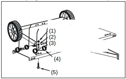
11. Assemble the axle bracket (1) on the outside
of the angle brackets using two M8×20 hex bolts
(3) and M8 hex lock nuts (2). The ends of the axle
bracket must point as shown in the figure. Tighten
and then slightly re-loosen the bolts and nuts.
12. Assemble the wheels to the axle bracket us-
ing two shoulder bolts (2) and two M10 hex lock
nuts (1). Tighten.
13. Fasten ten spring tines (4) to the square holes
in the bottom of the tine shield. Use a M8×25 car-
riage bolt (5), Ø8 big flat washer (3), Ø8 lock
washer (2) and M8 hex nut (1) for each spring
tine. Tighten.
NOTE: Spring tines must seat between dimples.
14. Assemble the spring align wires (1) through
the front and rear rows of spring tines, passing
the wires in between the hitch mount arms and
the tine shield. Bend the ends of the wires to se-
cure them.
© by WilTec Wildanger Technik GmbH Item 51705 Page 7
http://www.WilTec.de
http://www.aoyue.eu 01 2021-1
http://www.teichtip.de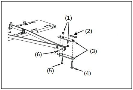
15. Assemble a hitch arm mount bracket to the
axle bracket using two M8×25 carriage bolts (3),
Ø8 lock washers (6) and M8 hex nuts (5). Do not
tighten yet.
16. Insert the lift handle (2) down through the tine
shield. Attach it to the hitch arm mount bracket
just assembled using an M8×20 hex bolt (4) and
an M8 hex lock nut (7). Tighten.
17. Position the hitch arm mount bracket so that
there is side tension on the lift handle (2) with grip
(1) when it is locked in the up position. Tighten
the nuts.

Operation and adjustments

Regular removal of thatch is critical to maintenance of a healthy lawn. Thatch is a layer of stems, clip-
pings, runners, roots and leaves that have not decayed. Excessive thatch prevents air, water and fertil-
izer from reaching the roots. The scarifier effectively dislodges excessive thatch from your lawn. Read
these instructions to help avoid improper adjustment and operation.

Proper adjustment of the tine shield and spring tines is important for effective performance. Refer to
the following steps for the proper adjustment before operating the scarifier.

1. Move the towing vehicle onto a level surface,
such as a driveway or garage floor and attach the
tine scarifier to the vehicle hitch.
2. To adjust the spring tine shield, lower the scari-
fier into operating position using the lift handle (2).
Loosen the two hex nuts and carriage bolts (1)
which fasten the rear of the hitch mount arm to
the hitch arm mount brackets. Adjust the tin shield
until it is level and both the front and rear spring
tines are in contact with the ground. Re-tighten
the hex nuts.

© by WilTec Wildanger Technik GmbH                Item 51705                                      Page 8
http://www.WilTec.de
http://www.aoyue.eu                                                                             01 2021-1
http://www.teichtip.de
3. If the scarifier appears to be “jumping” during
                                                      use, then extra weight should be added to the tine
                                                      shield. In most conditions extra weight will be
                                                      needed. Concrete patio blocks are recommended
                                                      for weight because of their low profile; however
                                                      any type of weight is suitable if it can be tied
                                                      down to the shield. Secure weight by using suit-
                                                      able binding material such as rubber tie down
                                                      straps or wire, fastening to the holes in the shield
                                                      flange.

Maintenance

    1.   Before each use check all nuts and bolts for tightness.
    2.   Lubricate wheels as needed.
    3.   If rust appears on the shield or spring tines, sand lightly and coat with enamel paint.
    4.   Always store in a dry area, and coat exposed metal with light oil when not in use.

© by WilTec Wildanger Technik GmbH               Item 51705                                          Page 9
http://www.WilTec.de
http://www.aoyue.eu                                                                                01 2021-1
http://www.teichtip.de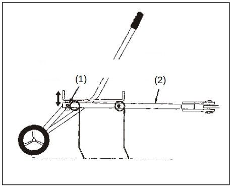
Explosion view and parts list

 №                     Name                   Qty. №                      Name                    Qty.
 1 Hitch arm mount bracket                      3    13 Hex lock nut M10                            2
 2 Hitch bracket                                2    14 Big flat washer Ø8                         10
 3 Spring tine                                 10    15 Hex bolt M8×20                             15
 4 Spring alignment wire                        2    16 Lock washer Ø8                             14
 5 Wheel                                        2    17 Hex nut M8                                 14
 6 Tine shield (40”)                            1    18 Hex lock nut M8                            19
 7 Hitch mount arm                              2    19 Carriage bolt M8×25                        14
 8 Lift plat                                    1    20 Handle grip                                 1
 9 Axle bracket                                 1    21 Hex bolt M8×50                              2
 10 Lift handle                                 1    22 Hex bolt M8×30                              2
 11 Shoulder bolt                               2    23 Hitch pin M8 (flat head)                    1
 12 Angle bracket                               4    24 Hair cotter pin Ø3                          1

Important notice:

The reprint or reproduction, even of excerpts, and any commercial use, even in part of this instructions
manual require the written permission of WilTec Wildanger Technik GmbH.

© by WilTec Wildanger Technik GmbH             Item 51705                                       Page 10
http://www.WilTec.de
http://www.aoyue.eu                                                                            01 2021-1
http://www.teichtip.de
You can also read